If you’re designing a PCB, you may wonder: which is better for your project, a 0 ohm resistor, a jumper, or a wire? This guide breaks down everything you need to know about 0 ohm resistors, their specs, functions, and how they compare to jumpers and wires. You’ll learn how to choose, test, and use 0 ohm resistors effectively so you can make the right choice for your PCB. Keep reading to solve all your doubts.
What Is A 0 Ohm Resistor?
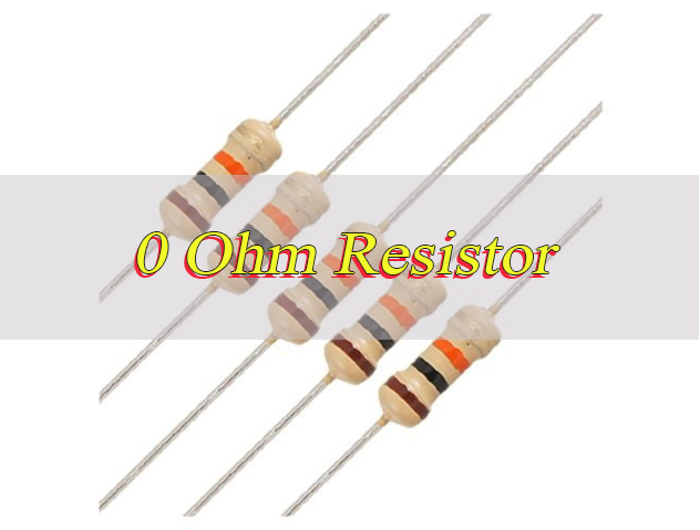
A 0 ohm resistor (or zero ohm resistor) is a passive electronic component that acts as a jumper or conductor in a standard resistor package. It is essentially a wire link packaged like a regular resistor, designed to connect traces on a printed circuit board without the need for separate jumpers or wires.
Contrary to its name, it does not have true 0 ohm resistance. Instead, it has a very low resistance, typically between 0.01 ohms and 0.1 ohms, depending on the manufacturer and package size. This low resistance lets it conduct current almost as efficiently as a wire, while retaining the form factor of a resistor, making it compatible with standard PCB assembly processes.
0 ohm resistors come in standard packages like 0402, 0603, 0805, and 1206. They integrate easily into PCB layouts using automated pick-and-place machines and are widely used in PCB design to simplify routing, enable design flexibility, and facilitate testing or modification.
What Is The Resistance Of A 0 Ohm Resistor?
A 0 ohm resistor does not have exactly 0 ohms of resistance. While it is often referred to as a zero ohm resistor, true zero resistance is not physically possible, and these components have a very low actual resistance instead.
Its actual resistance, called typical or nominal resistance, ranges from 0.01 ohms to 0.1 ohms, with most manufacturers specifying a maximum resistance of 0.1 ohms. This small resistance originates from the material used, usually a thin metal film or carbon film, and the physical size of the resistor itself.
For practical PCB use, this resistance is negligible and does not significantly affect current flow or voltage drops.Always check the datasheet for the exact resistance value, as it varies slightly by brand and package type.
What Does A 0 Ohm Resistor Do?
A 0 ohm resistor serves three main functions in PCB design, all simplifying circuit design and assembly.
First, it acts as a jumper or conductor. It connects two PCB points without needing a separate wire or jumper.
Second, it provides design flexibility. If you’re unsure about a connection for testing, different configurations, or future modifications, insert a zero ohm resistor temporarily. You can remove it later if needed.
Third, it facilitates automated assembly. Since 0 ohm resistors use standard resistor packages, they work with the same pick-and-place machines as other resistors. This eliminates manual jumper installation.
Additionally, 0 ohm resistors can break ground loops, isolate circuits, or mark test points on a PCB.
Why 0 Ohm Resistor Is Used In PCB?
0 ohm resistors are a staple in PCB design for practical reasons jumpers and wires cannot match.
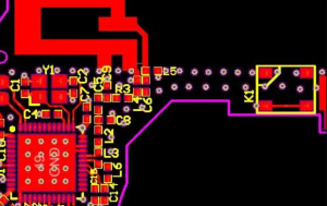
They simplify PCB routing. When two components need connection but their pads are not adjacent, a 0 ohm resistor bridges the gap. No complex wire routing or vias are needed.
They support automated manufacturing. Manual jumpers take time to install and are prone to errors. 0 ohm resistors fit seamlessly into automated pick-and-place and soldering processes.
They enable design flexibility. Engineers use 0 ohm resistors to create modular PCBs. Different sections can be connected or disconnected by adding or removing the resistor.
They improve PCB reliability. 0 ohm resistors are less likely to come loose than jumpers. Their standard package protects the connection from damage during handling or operation.
What Is The Color Code For A 0 Ohm Resistor?
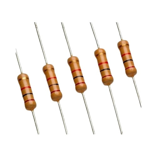
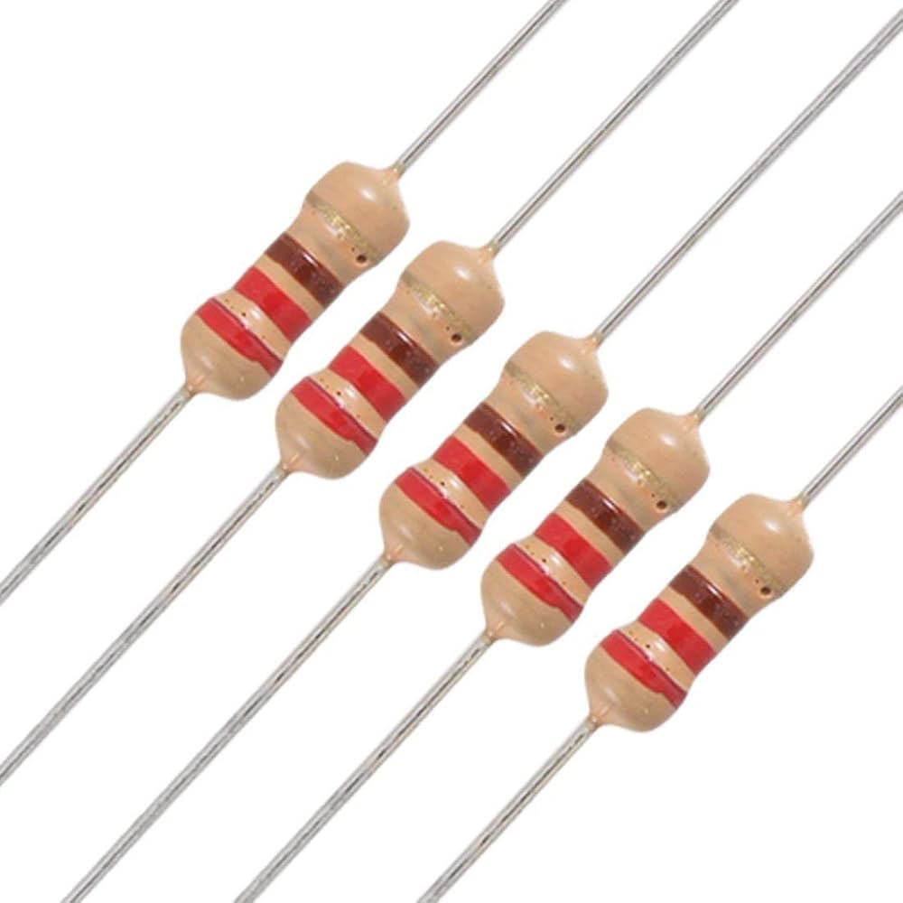
0 ohm resistors have a simple color code, easy to identify even for beginners, and it differs significantly from standard resistors that use multiple color bands to indicate resistance values. Axial-lead through-hole 0 ohm resistors, in particular, are generally marked with a single black band. This black band serves as the symbol for 0 ohms in resistor color coding, as black is universally used to represent the digit 0 in resistor color marking systems.
While the single black band is the most common marking for 0 ohm resistors, some may have two black bands, though this is less prevalent. For four-band 0 ohm resistors, the first three bands are black to signify 0 ohms. The fourth band is used for indicating tolerance and can be gold, silver, or omitted entirely, depending on the manufacturer’s specifications. Gold typically indicates a ±5% tolerance and silver a ±10% tolerance, consistent with standard resistor color code conventions.
This simplified color code design makes it easy to distinguish 0 ohm resistors from other components on a PCB, which is critical for efficient assembly and troubleshooting. It is worth noting that surface-mount 0 ohm resistors are often marked with one or multiple “0” instead of color bands. The color code, however, remains the standard for through-hole types, ensuring consistency in identification across different resistor formats.
How Much Current Can A 0 Ohm Resistor Handle?
A 0 ohm resistor’s current-carrying capacity is not fixed and depends on three key factors: its package size, the material it is made of, and the ambient temperature of the operating environment. These factors work together to determine how much current the resistor can safely conduct without experiencing failure.
Package size is a primary determinant of current capacity, with smaller packages handling less current and larger packages accommodating more. For instance, a 0402 0 ohm resistor typically handles 0.5A to 1A, a 0603 package handles 1A to 2A, and a 1206 package can handle 2A to 3A. It is important to check the 0 ohm resistor datasheet for the exact current rating, as values can vary slightly by manufacturer.
Exceeding the specified current rating can lead to serious issues, including the resistor overheating, melting, or failing entirely, which can damage the entire PCB. For high-current circuits, it is crucial to choose a zero ohm resistor with a current rating that exceeds the circuit’s maximum current to ensure safe and reliable operation.
0 Ohm Resistor Datasheet Specification
A 0 ohm resistor’s datasheet has critical specifications every PCB engineer should review before selection. Below is a detailed table of key datasheet specifications for easy reference:
| Specification Type | Typical Value/Description | Notes |
|---|---|---|
| Typical Resistance | 0.01 ohms – 0.1 ohms | Actual resistance varies slightly by manufacturer and package size |
| Maximum Resistance | 0.1 ohms (most manufacturers) | Critical for ensuring minimal voltage drop in circuits |
| Current Rating | 0.5A – 3A (varies by package size) | 0402: 0.5A-1A; 0603:1A-2A; 1206:2A-3A; check datasheet for exact values |
| Voltage Rating | 25V – 100V | Depends on resistor material and package design |
| Operating Temperature Range | -55°C to 155°C | Temperature above 70°C may require current derating |
| Package Size | 0402, 0603, 0805, 1206 (common) | Larger packages have higher current-carrying capacity |
| Material | Metal film, carbon film, or thick film | Affects resistance consistency and temperature stability |
| Additional Datasheet Content | Soldering guidelines, storage conditions, reliability ratings | Essential for proper installation and long-term performance |
Always refer to the datasheet to ensure compatibility with your PCB’s operating conditions. Ignoring specs can lead to component failure and PCB malfunctions.
How To Test 0 Ohm Resistor?
Testing a zero ohm resistor is straightforward with a multimeter, and the process differs slightly for on-PCB and off-PCB testing. Below are the detailed, step-by-step test steps, along with result judgment and key notes:
- Prepare tools and confirm safety: Use a digital multimeter (ensure it is calibrated to avoid inaccurate readings). If testing on a PCB, turn off the circuit power and disconnect the power source to prevent short circuits or false readings caused by residual voltage.
- Set the multimeter correctly: Switch the multimeter to resistance mode (marked with Ω), and select the lowest resistance range (usually 200Ω). This range ensures high precision for measuring the low resistance of 0 ohm resistors, which is critical for accurate judgment.
- Perform the test operation: For off-PCB testing, touch the two probes of the multimeter firmly to the two leads of the 0 ohm resistor. For on-PCB testing, touch the probes to the two pads of the resistor on the PCB, avoiding contact with adjacent components to prevent interference.
- Judge test results: A normal 0 ohm resistor will show a reading between 0.01 ohms and 0.1 ohms, which aligns with its nominal low resistance. A reading higher than 10 ohms indicates the resistor is faulty or damaged. A reading of “OL” (open loop) means the resistor is open and cannot conduct current, requiring replacement.
- Post-test notes: After testing, turn off the multimeter and restore the circuit connection (if on-PCB testing). Regular testing of 0 ohm resistors in key circuits helps detect potential failures early and avoid damage to the entire PCB.
Difference Between 0 Ohm Resistor VS Jumper: Which Is Better?
Choosing between a zero ohm resistor and a jumper depends on your PCB’s design, manufacturing process, and requirements. Below is a detailed comparison table to help you decide:
| Feature | 0 Ohm Resistor | Jumper |
| Form Factor | Standard resistor package (0402, 0603, etc.), fits PCB pads | Small wire loop or pin header, requires dedicated jumper pads |
| Automated Assembly | Compatible with pick-and-place machines, no manual labor needed | Requires manual installation, slow and prone to errors |
| Design Flexibility | Easily removable/replaceable for circuit modifications or testing | Permanent once installed; difficult to remove without damaging the PCB |
| Current Capacity | Limited by package size (0.5A–3A) | Higher current capacity (depends on wire gauge) |
| Reliability | High; soldered securely to PCB, less likely to come loose | Low; prone to loosening or breaking due to vibration or handling |
| Best For | Automated manufacturing, modular designs, temporary connections, PCB routing simplification | Low-volume projects, manual assembly, high-current applications where space is not an issue |
Difference Between 0 Ohm Resistor VS Wire: Which Is Better?
A zero ohm resistor and a wire both conduct current, but they differ in form factor, usability, and reliability. Below is a detailed comparison table to help you choose the right option for your PCB:
| Feature | 0 Ohm Resistor | Wire |
| Form Factor | Compact, standard resistor package; fits neatly on PCB pads | Flexible or rigid wire; requires space for routing, may cause clutter |
| Automated Assembly | Fully compatible with pick-and-place and soldering machines | Requires manual routing and soldering; not suitable for automated lines |
| PCB Routing | Simplifies routing; bridges gaps between non-adjacent pads without vias | Requires complex routing; may block other components or create short circuits |
| Modification | Easily removed or replaced for circuit changes or testing | Difficult to modify; cutting or re-soldering may damage the PCB |
| Resistance | Low (0.01–0.1 ohms); consistent across temperature changes | Very low (depends on length and gauge); increases with length |
| Best For | Compact PCBs, automated manufacturing, modular designs, test points | High-current applications, large PCBs, temporary connections during prototyping |
How To Choose The Right 0 Ohm Resistor for Your PCB Project?
Choosing the right 0 ohm resistor requires considering five core, evidence-based factors to ensure compatibility, reliability, and optimal performance for your PCB project. Below are the detailed, concise guidelines:
- Select the appropriate package size: Choose based on your PCB’s space constraints and current requirements. Compact PCBs are ideal for 0402 packages, while 0603 and 0805 suit general-purpose designs. For high-current scenarios, 1206 packages are preferred as they offer higher current-carrying capacity. Ensure the package fits existing PCB pads to avoid assembly issues.
- Verify the current rating: The current rating must exceed the maximum current of your circuit to prevent overheating, melting, or resistor failure. Typical ratings vary by package: 0402 (0.5A–1A), 0603 (1A–2A), 1206 (2A–3A). Always check the manufacturer’s datasheet for exact values, as material and ambient temperature also affect current capacity.
- Confirm the resistance value: Aim for a nominal resistance of 0.01–0.1 ohms, the standard range for 0 ohm resistors. This low resistance ensures negligible voltage drop and does not interfere with circuit performance. Exact values vary slightly by brand and package, so cross-check the datasheet to avoid selecting components with excessive resistance.
- Match to your application scenario: Align the resistor with your PCB’s manufacturing and functional needs. Use 0 ohm resistors for automated assembly, modular designs, or temporary connections for testing. Opt for jumpers or wires instead for low-volume manual assembly or high-current applications where space is not limited.
- Choose a reputable manufacturer and review the datasheet: Select reliable manufacturers to ensure consistent performance and quality, as low-quality 0 ohm resistors may have unstable resistance or poor durability. Always review the datasheet to confirm key specs (voltage rating, operating temperature, material) and ensure compatibility with your PCB’s operating environment.
FAQs About Zero Ohm Resistor
Q1: Is there voltage across a 0 ohm resistor?
A1: No, there is no significant voltage across a 0 ohm resistor. 0 ohm resistors have very low resistance, so the voltage drop is negligible. For example, 1A through a 0.1 ohm 0 ohm resistor creates a 0.1V drop, too small to affect most circuits.
Q2: Can you jump a 0 ohm resistor?
A2: Yes, you can jump a 0 ohm resistor, but it is unnecessary. A 0 ohm resistor already acts as a jumper. If it is faulty, you can temporarily jump it with a wire to test the circuit before replacement.
Q3: Can a wire be considered a 0 ohm resistor?
A3: No, a wire cannot be considered a 0 ohm resistor. Wires lack the standard resistor package and specs. 0 ohm resistors are designed for PCB assembly and modularity, while wires are not.
Q4: Can you replace a zero-ohm resistor with a wire?
A4: Yes, you can replace a zero-ohm resistor with a wire in most cases. Both conduct current with low resistance, so the circuit works the same. This removes modification flexibility and compatibility with automated assembly.
Q5: Is a 0 ohm resistor a short?
A5: No, a 0 ohm resistor is not a short circuit. A short has zero resistance, while a 0 ohm resistor has 0.01–0.1 ohms. This small resistance prevents infinite current flow, making it safe for circuits.
Q6: Is 0 ohms good continuity?
A6: Yes, 0 ohms or very low resistance indicates good continuity. Continuity tests check for complete circuits. A 0 ohm reading means the path is unobstructed and current flows freely.
Q7: Is 0 ohms open or closed?
A7: 0 ohms indicates a closed circuit. A closed circuit allows current flow. An open circuit shows “OL” on a multimeter, meaning no current can flow.
Q8: Is a 0 ohm resistor a fuse?
A8: No, a 0 ohm resistor is not a fuse. Fuses break to protect circuits from overcurrent. 0 ohm resistors conduct current and fail when overloaded but do not act as protective fuses.