High-frequency PCB materials are used when a circuit board must support stable signal transmission, low dielectric loss, controlled impedance, and reliable RF performance. In RF, microwave, radar, antenna, 5G, satellite, and high-speed communication products, standard FR4 may not provide enough electrical stability at higher frequencies. This is why many projects use Rogers PCB materials, low-loss laminates, PTFE-based materials, ceramic-filled materials, or hybrid high-frequency stack-ups.
The right material choice affects insertion loss, return loss, phase stability, impedance accuracy, thermal behavior, moisture resistance, manufacturability, and final product reliability. For procurement and engineering teams, high-frequency PCB material selection is not only about choosing a famous material brand. It requires a full review of frequency, Dk, Df, copper roughness, board thickness, stack-up, surface finish, testing method, and production capability.
What Are High-Frequency PCB Materials?
High-frequency PCB materials are special circuit board laminates designed for RF, microwave, millimeter-wave, and high-speed signal applications. Compared with standard FR4, they provide lower signal loss, more stable dielectric properties, better impedance control, and stronger frequency performance.
Common high-frequency PCB materials include Rogers PCB materials, PTFE-based laminates, hydrocarbon ceramic laminates, low-loss FR4 alternatives, ceramic-filled materials, and hybrid RF laminates. Rogers PCB materials are widely used because they offer several laminate families for RF, microwave, antenna, radar, 5G, and high-speed applications.
These materials are selected when the PCB must behave as part of the signal path, not only as a mechanical support. In high-frequency circuits, small material changes can affect signal speed, wavelength, resonance, phase delay, impedance, and RF testing results.
Why Are High-Frequency PCB Materials Important?
High-frequency PCB materials are important because signal behavior becomes more sensitive as frequency increases. At higher frequencies, dielectric loss, conductor loss, copper roughness, dielectric thickness variation, and impedance mismatch can all reduce circuit performance.
If the wrong material is selected, the PCB may suffer from high insertion loss, unstable antenna tuning, poor return loss, phase drift, EMI issues, weak RF output, or inconsistent batch performance. These problems may not appear in a simple open-short electrical test, but they can fail during RF testing or real product operation.
For applications such as 5G antennas, radar modules, RF power amplifiers, microwave filters, satellite boards, and high-speed test equipment, high-frequency PCB materials directly affect product reliability, signal quality, and production yield.
How Do High-Frequency PCB Materials Work?
High-frequency PCB materials work by providing a stable dielectric environment for electromagnetic signal transmission. The dielectric layer controls signal propagation, while the copper foil, trace geometry, reference plane, and laminate thickness control impedance and signal loss.
Key material properties include dielectric constant, dissipation factor, dielectric thickness, copper roughness, moisture absorption, thermal conductivity, coefficient of thermal expansion, and dimensional stability. These properties must remain stable across frequency, temperature, humidity, and production batches.
For example, a small shift in dielectric constant may change impedance or antenna resonance. A rough copper surface may increase conductor loss at microwave frequencies. A weak lamination process may create reliability problems in hybrid stack-ups. That is why high-frequency PCB material selection must be connected with both RF design and PCB manufacturing control.
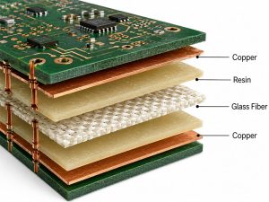
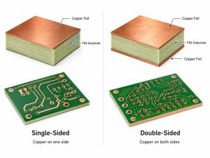
What Is the Structure of a High-Frequency PCB?
A high-frequency PCB usually includes high-frequency laminate, copper foil, bonding material, ground plane, solder mask, surface finish, and sometimes FR4 supporting layers. The exact structure depends on the frequency range, impedance requirement, layer count, thermal load, and assembly method.
| Layer / Material | Main Function | Key Selection Points |
|---|---|---|
| High-frequency laminate | Provides RF dielectric base | Dk, Df, thickness, stability |
| Copper foil | Carries RF signals and current | Roughness, thickness, peel strength |
| Bondply or prepreg | Bonds multilayer structures | Dk match, flow control, lamination reliability |
| Ground plane | Controls return path and shielding | Copper thickness, spacing, flatness |
| Solder mask | Protects copper areas | RF impact, adhesion, heat resistance |
| Surface finish | Supports soldering and contact quality | ENIG, immersion silver, OSP, hard gold |
For RF boards, dielectric thickness and copper roughness are especially important. Even small changes in these areas can shift impedance, increase insertion loss, or change resonance behavior.
What Types of High-Frequency PCB Materials Are Common?
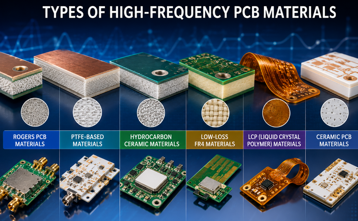
High-frequency PCB materials can be grouped by resin system, electrical performance, cost level, and application area. Common types include Rogers PCB materials, PTFE laminates, hydrocarbon ceramic laminates, low-loss FR4 materials, LCP materials, and ceramic PCB materials.
| Material Type | Typical Features | Common Applications |
|---|---|---|
| Rogers PCB materials | Stable RF performance, multiple laminate families | RF modules, radar, antennas, 5G |
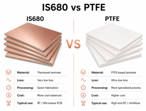
| PTFE laminates | Very low loss, strong microwave performance | Microwave, satellite, defense |
| Hydrocarbon ceramic laminates | Good RF performance and manufacturability | Commercial RF, antennas, filters |
| Low-loss FR4 | Lower cost than advanced RF laminates | High-speed digital, moderate frequency |
| LCP materials | Low moisture absorption, good RF performance | Antenna, flexible RF, compact modules |
| Ceramic PCB materials | High thermal stability and insulation | RF power, laser, aerospace, medical |
The best choice depends on frequency, loss budget, board size, cost target, thermal demand, manufacturing process, and test requirements. Rogers PCB materials are often selected when projects need a practical balance of RF performance and manufacturability.
What Are Rogers PCB Materials?
Rogers PCB materials are advanced circuit laminates used for high-frequency, RF, microwave, and high-speed electronic products. They are known for low dielectric loss, stable dielectric constant, controlled thickness, and reliable RF performance.
Common Rogers material families include RO4000 Series, RO3000 Series, RT/duroid materials, TC Series materials, and other high-speed circuit materials. These materials are used in antennas, RF front-end modules, radar boards, satellite communication systems, microwave circuits, and 5G infrastructure.
Rogers PCB materials are not selected only because of the brand name. They are chosen because specific Rogers laminates can provide predictable Dk, low Df, stable impedance behavior, and better RF repeatability compared with standard FR4 materials.
What Are RO4000 Series Materials?
RO4000 Series materials are commonly used in commercial RF and microwave PCB projects. They are often selected when the design needs better RF performance than FR4, but still requires practical processing, reasonable cost, and stable production.
RO4003C, RO4350B, and related Rogers PCB materials are widely used in RF modules, antennas, microwave boards, filters, power amplifiers, and communication systems. They offer a useful balance between electrical performance and manufacturability.
For many RF projects, RO4000 materials are a practical choice because they can support controlled impedance, low loss, stable fabrication, and cost control better than many high-end PTFE-only options.
What Are RO3000 Series Materials?
RO3000 Series materials are ceramic-filled PTFE composites used for more demanding microwave and RF applications. They are often selected when the circuit requires stable dielectric constant, low loss, and good dimensional control.
RO3003, RO3006, RO3010, and related Rogers PCB materials are commonly used in radar systems, microwave circuits, antenna products, multilayer RF designs, 5G modules, and high-frequency test equipment.
These materials are especially useful when a project needs stable electrical behavior across frequency and temperature. For radar and microwave products, this stability can help reduce frequency drift, phase error, and inconsistent RF test results.
What Are RT/duroid Materials?
RT/duroid materials are high-performance Rogers PCB materials used in demanding RF, microwave, aerospace, defense, satellite, and broadband applications. They are often selected when the design requires very low loss, stable signal behavior, and high reliability.
These materials are common in satellite communication boards, radar systems, phased-array antennas, microwave modules, aerospace electronics, and defense-grade RF circuits. They can provide excellent high-frequency performance, but usually require stricter fabrication control.
Compared with more cost-balanced high-frequency PCB materials, RT/duroid laminates may increase material and processing cost. However, they are often justified when the project has strict RF loss, phase stability, or reliability requirements.
What Material Properties Matter Most?
The most important properties of high-frequency PCB materials include Dk, Df, copper roughness, dielectric thickness, thermal conductivity, CTE, moisture absorption, and dimensional stability.
| Property | Why It Matters |
|---|---|
| Dielectric constant | Controls impedance, wavelength, antenna size, and phase |
| Dissipation factor | Affects dielectric loss and signal efficiency |
| Copper roughness | Increases conductor loss at higher frequencies |
| Thickness tolerance | Affects impedance and coupling accuracy |
| Thermal conductivity | Helps control RF power heat rise |
| Moisture absorption | Reduces frequency drift in humid environments |
| CTE | Affects plated hole and lamination reliability |
| Dimensional stability | Supports registration and repeatable production |
A low Df value is important, but it is not the only selection factor. A material can still create problems if thickness tolerance, copper profile, lamination behavior, or fabrication capability is not suitable for the design.
How Do High-Frequency PCB Materials Compare with FR4?
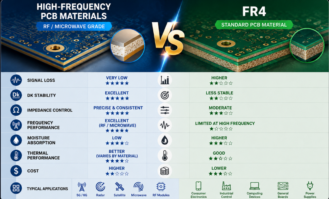
High-frequency PCB materials and FR4 are used for different performance levels. FR4 is suitable for general electronics, control boards, and many digital circuits. High-frequency PCB materials are used when signal loss and dielectric stability become critical.
| Comparison Item | High-Frequency PCB Materials | Standard FR4 |
|---|---|---|
| Signal loss | Lower loss at RF and microwave frequencies | Higher loss at high frequencies |
| Dk stability | More controlled and stable | Less stable at high frequency |
| Impedance control | Better for RF and microwave circuits | Suitable for general circuits |
| Cost | Higher | Lower |
| Manufacturing difficulty | Requires tighter process control | Easier and widely available |
| Best use | RF, radar, antenna, microwave, 5G | Control boards, standard electronics |
| Main risk | Higher cost and process sensitivity | Limited RF performance |
FR4 can still work in some lower-frequency or cost-sensitive designs. However, for antennas, RF filters, radar boards, microwave modules, and high-speed communication products, high-frequency PCB materials are usually more reliable.
How Do Rogers PCB Materials Compare with Other High-Frequency PCB Materials?
Rogers PCB materials are one category of high-frequency PCB materials. They are often compared with PTFE laminates, low-loss FR4, LCP, and ceramic PCB materials.
| Comparison Item | Rogers PCB Materials | Low-Loss FR4 | Ceramic PCB Materials |
|---|---|---|---|
| RF performance | Strong and stable | Moderate | Strong in RF and thermal applications |
| Cost | Medium to high | Lower | Usually higher |
| Fabrication | Depends on material family | Easier | Specialized process |
| Thermal behavior | Varies by series | Moderate | Often excellent |
| Mechanical behavior | Laminate-based PCB process | Similar to FR4 | Hard but brittle |
| Best use | RF, microwave, radar, antenna, 5G | High-speed digital, lower RF demand | RF power, laser, medical, aerospace |
Rogers PCB materials are often preferred when the project requires better RF stability than low-loss FR4, but still needs practical PCB fabrication. Ceramic materials may be selected when thermal conductivity, insulation stability, or high-power operation becomes more important.
What Manufacturing Challenges Occur with High-Frequency PCB Materials?
High-frequency PCB materials require tighter manufacturing control than standard FR4. Common challenges include drilling quality, plating reliability, copper adhesion, lamination control, registration accuracy, surface cleanliness, impedance variation, and material handling damage.
PTFE-based materials may require special drilling, plasma treatment, or surface preparation. Hybrid stack-ups using Rogers PCB materials and FR4 also require careful control of CTE mismatch, lamination cycle, material flow, and layer registration.
Small manufacturing variations can create large RF differences. Rough copper, dielectric thickness variation, poor etching, weak plating, or contamination can increase loss and shift impedance.
What Design Rules Matter for High-Frequency PCB Materials?
Design rules for high-frequency PCB materials should focus on electrical behavior, not only routing space. Important rules include controlled impedance, short RF paths, smooth trace transitions, stable ground reference, proper via placement, and clear stack-up definition.
For antenna and microwave circuits, avoid unnecessary stubs, sharp corners, uncontrolled dielectric changes, and inconsistent ground spacing. Trace width, dielectric thickness, copper roughness, and surface finish should be reviewed together.
For hybrid designs, clearly define which layers use Rogers PCB materials and which layers use FR4 or other materials. This helps reduce quotation errors, production confusion, and RF test failure risk.
What Surface Finishes Are Used for High-Frequency PCBs?
Common surface finishes for high-frequency PCBs include ENIG, immersion silver, OSP, immersion tin, and hard gold. The right finish depends on solderability, contact requirements, shelf life, cost, and RF sensitivity.
| Surface Finish | Advantages | Common Use |
|---|---|---|
| ENIG | Flat surface and good shelf life | RF modules, fine-pitch assembly |
| Immersion silver | Good conductivity and solderability | RF and microwave circuits |
| OSP | Thin and cost-effective | Fast assembly projects |
| Immersion tin | Good flatness | Selected soldering applications |
| Hard gold | Wear resistance | RF contacts, edge connectors |
Surface finish can affect RF performance at microwave and millimeter-wave frequencies. For sensitive circuits, finish thickness, surface roughness, and pad geometry should be reviewed before production.
What Quality Tests Are Needed for High-Frequency PCB Materials?
High-frequency PCB materials require both standard PCB inspection and RF-related verification. Quality tests may include electrical test, impedance test, AOI, X-ray, dimensional inspection, cross-section analysis, solderability testing, thermal stress testing, and RF testing when required.
| Test Item | Purpose |
|---|---|
| Electrical test | Checks open and short circuits |
| Impedance test | Confirms controlled impedance performance |
| AOI | Detects trace defects and spacing issues |
| X-ray inspection | Checks hidden structures and vias |
| Cross-section | Checks plating, hole wall, and lamination quality |
| Dimensional inspection | Verifies outline, holes, and registration |
| Solderability test | Confirms assembly readiness |
| RF test | Confirms insertion loss, return loss, or antenna performance |
A board may pass standard electrical testing but still fail RF performance. For high-frequency projects, impedance control and RF testing are often more meaningful than open-short testing alone.
What Common Problems Happen with High-Frequency PCBs?
Common problems include impedance mismatch, high insertion loss, poor return loss, delamination, drilling defects, plating failure, registration shift, soldering issues, contamination, and unstable RF test results.
Impedance mismatch may come from wrong material data, dielectric thickness variation, inaccurate etching, incorrect copper thickness, or poor stack-up control. High insertion loss may result from high Df material, rough copper, long trace paths, or unsuitable surface finish.
Many failures are caused by incomplete communication before production. The manufacturer should know exact material grade, copper thickness, dielectric thickness, impedance target, surface finish, stack-up, and RF test requirements before manufacturing starts.
How to Choose the Right High-Frequency PCB Materials?
Choosing the right high-frequency PCB materials starts with frequency, signal type, loss budget, power level, impedance target, board size, operating temperature, and product environment.
For cost-sensitive RF designs, RO4000 Series Rogers PCB materials may be practical. For more stable microwave multilayer designs, RO3000 Series materials may be considered. For low-loss aerospace, satellite, broadband, or defense applications, RT/duroid materials may be suitable.
A good selection process should review Dk, Df, thickness tolerance, copper roughness, thermal performance, surface finish, fabrication complexity, material availability, and test requirements together. The best material is the one that meets RF performance and production reliability at the same time.
What Factors Affect the Cost of High-Frequency PCB Materials?
High-frequency PCB cost depends on material grade, laminate thickness, copper thickness, layer count, impedance tolerance, via structure, surface finish, drilling difficulty, testing requirements, and order quantity.
| Cost Factor | Why It Affects Price | Cost Control Suggestion |
|---|---|---|
| Material grade | Rogers PCB materials and specialty laminates cost more | Match material to real RF demand |
| Layer count | More layers increase lamination complexity | Keep RF stack-up as simple as possible |
| Impedance tolerance | Tight tolerance requires more process control | Use realistic tolerance where possible |
| Copper profile | Low-profile copper may cost more | Use where insertion loss matters |
| Surface finish | ENIG, silver, or hard gold affects cost | Choose based on RF and assembly needs |
| RF testing | Special testing adds time and cost | Define required test items early |
| Quantity | Small batches have higher setup cost | Plan prototype and batch needs together |
Choosing a cheaper material may not reduce total cost if the board fails RF testing. Material selection should balance performance, manufacturability, and long-term reliability.
Where Are High-Frequency PCB Materials Commonly Used?
High-frequency PCB materials are used in products that require stable RF, microwave, millimeter-wave, or high-speed signal performance.
5G and wireless communication: antennas, RF front-end boards, base station modules, filters, and power amplifiers.
Automotive electronics: radar modules, ADAS sensors, vehicle communication systems, and high-frequency control units.
Aerospace and defense: radar systems, satellite communication boards, avionics, phased-array systems, and microwave modules.
Industrial electronics: RF sensors, test instruments, measurement equipment, and high-speed control modules.
Medical electronics: RF imaging systems, high-frequency diagnostic equipment, and compact signal modules.
Consumer and IoT products: wireless modules, high-frequency antennas, wearable communication products, and smart devices.
What Should You Confirm Before Ordering High-Frequency PCBs?
Before ordering high-frequency PCBs, confirm material grade, laminate thickness, copper thickness, stack-up, impedance target, surface finish, tolerance, via structure, solder mask requirement, and testing method.
You should provide Gerber files, drill files, stack-up drawings, impedance requirements, RF performance notes, material callouts, quantity, and assembly requirements. If the board uses Rogers PCB materials in a hybrid stack-up, clearly mark which layers use Rogers and which layers use FR4.
For RF projects, prototype validation is strongly recommended before mass production. Testing real boards under working frequency conditions helps confirm whether the selected material, stack-up, and fabrication process match the design goal.
Why Choose EBest for High-Frequency PCB Manufacturing?
EBest Technology provides one-stop PCB solutions, including PCB design, PCB prototype, mass production, component sourcing, PCB assembly, and box-build assembly. Its product range includes standard FR4 PCB, metal-based PCB, ceramic PCB, flexible PCB, rigid-flex PCB, and high frequency PCB, supporting different electronic manufacturing needs.
For high-frequency PCB projects, EBest can support material review, Rogers PCB materials selection, stack-up confirmation, controlled impedance production, prototype validation, batch manufacturing, PCB assembly, and quality inspection. This is useful for RF modules, antennas, communication boards, radar boards, microwave products, and high-speed electronic systems.
EBest also supports quality and compliance systems such as IATF 16949, ISO 9001:2015, ISO 13485:2016, AS9100D, REACH, RoHS, and UL-related requirements. These capabilities help customers manage industrial, automotive, medical, aerospace, and export-oriented high-frequency PCB projects with more confidence.
FAQs About High-Frequency PCB Materials
Q1: What are high-frequency PCB materials used for?
A1: High-frequency PCB materials are used for RF, microwave, radar, antenna, 5G, satellite, aerospace, and high-speed communication circuits. They help reduce signal loss, control impedance, improve frequency stability, and support more predictable electrical performance than standard FR4.
Q2: Are Rogers PCB materials the same as high-frequency PCB materials?
A2: Rogers PCB materials are one important type of high-frequency PCB materials. They include several laminate families used for RF, microwave, radar, antenna, and high-speed applications, but high-frequency materials can also include PTFE, LCP, low-loss FR4, and ceramic materials.
Q3: Why are high-frequency PCB materials better than FR4 for RF circuits?
A3: High-frequency PCB materials usually provide lower dielectric loss, more stable dielectric constant, better impedance control, and lower signal distortion. FR4 may work for general electronics, but it becomes less predictable at higher RF and microwave frequencies.
Q4: What does Dk mean in high-frequency PCB materials?
A4: Dk means dielectric constant. It affects impedance, wavelength, phase delay, antenna size, and signal propagation speed. In RF design, stable Dk is important because small changes can shift frequency response and reduce product performance.
Q5: What does Df mean in Rogers PCB materials?
A5: Df means dissipation factor. It describes dielectric loss. Lower Df usually means lower signal loss, which is important for RF, microwave, antenna, radar, satellite, and high-speed communication circuits.
Q6: Can Rogers PCB materials be combined with FR4?
A6: Yes. Hybrid stack-ups using Rogers PCB materials and FR4 are common when only certain RF layers need high-frequency performance. However, the stack-up must be carefully designed to manage lamination, CTE mismatch, impedance control, and reliability.
Q7: What causes signal loss in high-frequency PCBs?
A7: Signal loss can come from dielectric loss, copper roughness, impedance mismatch, long RF traces, poor transitions, via discontinuities, surface finish effects, and weak stack-up control. Material selection and fabrication quality both matter.
Q8: What surface finish is best for high-frequency PCBs?
A8: ENIG and immersion silver are commonly used, but the best choice depends on frequency, soldering process, shelf life, contact requirements, and RF sensitivity. For sensitive circuits, surface finish thickness and roughness should be reviewed before production.
Q9: Why are high-frequency PCBs more expensive?
A9: High-frequency PCBs cost more because the materials are more expensive and manufacturing requires tighter process control. Cost may also increase due to controlled impedance, special drilling, hybrid lamination, RF testing, and strict tolerance requirements.
Q10: What files are needed for a high-frequency PCB quotation?
A10: Provide Gerber files, drill files, stack-up, exact material grade, copper thickness, impedance requirements, surface finish, board thickness, tolerance, quantity, drawings, and RF testing requirements. For assembly, also provide BOM and placement files.
Q11: Can high-frequency PCBs support PCB assembly?
A11: Yes. High-frequency PCBs can support SMT assembly and selected through-hole assembly. The assembly process should consider material thermal behavior, soldering profile, surface finish, component layout, and RF-sensitive areas.
Q12: How do I choose between RO4000, RO3000, and RT/duroid materials?
A12: RO4000 materials are often used for cost-effective RF designs. RO3000 materials are suitable for stable microwave and radar applications. RT/duroid materials are often selected for very low-loss, aerospace, satellite, broadband, and defense-grade RF products.
Conclusion
High-frequency PCB materials are selected when a circuit needs low signal loss, stable dielectric performance, controlled impedance, high-frequency reliability, and consistent RF behavior. Rogers PCB materials are widely used because they provide multiple RF laminate options for antennas, radar, microwave circuits, 5G modules, and high-speed communication systems.
For RF and microwave projects, do not choose materials by brand name alone. Review Dk, Df, thickness tolerance, copper profile, impedance target, surface finish, manufacturing capability, and testing requirements before confirming the PCB stack-up.
If you need high-frequency PCB materials, Rogers PCB materials, Rogers PCB manufacturing, high-frequency PCB production, controlled impedance PCB, RF PCB assembly, OEM production, ODM development, sample testing, batch production, or custom engineering solutions, please contact our team at sales@bestpcbs.com for technical support and quotation service.