
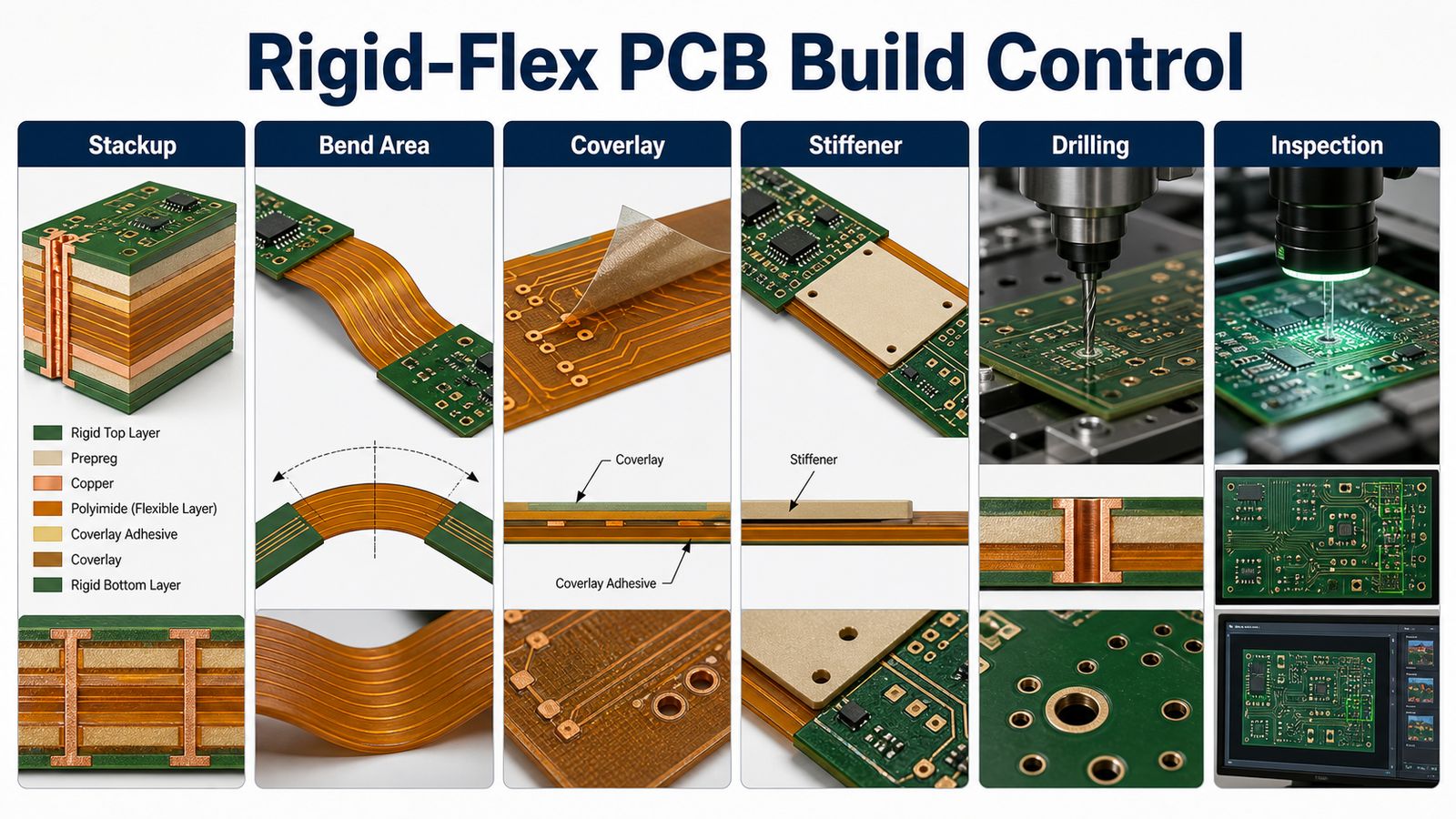
A rigid-flex PCB manufacturer must control the rigid board sections, flexible bend areas, stackup, materials, coverlay, stiffeners, drilling, assembly and inspection as one connected build. If those details are quoted separately, the buyer may receive a board that looks manufacturable on paper but fails during bending, assembly or repeat production.
For buyers, the right supplier is not only the one that can make a flex tail. The right supplier reviews whether the rigid-flex structure can be fabricated, assembled, tested and delivered with fewer surprises. EBest Circuit supports rigid-flex PCB projects by reviewing fabrication, PCBA, BOM, CPL, bend area and inspection requirements before production starts.
Is your rigid-flex PCB quote ignoring the bend and assembly risks?
Rigid-flex PCB projects often become expensive when a supplier treats the design like a rigid board with a flexible extension.
- The stackup does not clearly define rigid layers, flex layers, coverlay, adhesive, stiffener or bend area requirements.
- The design looks compact, but the bend transition, drill placement or copper geometry creates manufacturing risk.
- Assembly drawings arrive late, so connector placement, component clearance, panelization and fixture needs are not reviewed together.
- The buyer needs repeat production, but the quote does not define material route, inspection scope or documentation expectations.
- The first price looks attractive, but later DFM changes, flex material confirmation or PCBA questions delay the actual build.
EBest Circuit helps buyers turn rigid-flex PCB files into a controlled build plan:
- We review Gerber or ODB++ files, stackup, rigid/flex layer structure, flex position, bend area, coverlay, stiffener and board thickness before quote assumptions are locked.
- We connect fabrication review with PCBA, BOM, CPL, assembly drawings, connector details and inspection needs when the customer needs assembled rigid-flex boards.
- We check DFM risks around rigid-flex transitions, drilling, solder mask, copper, panelization, bend area and test access before production starts.
- We use project-confirmation language for HDI, special materials and tight requirements instead of promising every structure as a standard build.
- We help buyers compare suppliers by engineering response, quote clarity, manufacturing route and production planning, not only by the first unit price.
What a Rigid-Flex PCB Manufacturer Must Control
A rigid-flex PCB manufacturer must control the mechanical bend behavior and the electrical PCB build at the same time.
Rigid-flex boards combine rigid PCB sections with flexible polyimide areas. That combination reduces connectors and cable assemblies, but it also creates new risks around stackup, flex transition, drilling, copper routing, coverlay, stiffeners and assembly handling. A useful quote should show that the manufacturer has reviewed those risks before confirming production.
Where Rigid-Flex PCB Projects Usually Fail Before Production
Rigid-flex PCB projects usually fail before production when the design files do not explain how the board should bend, assemble and repeat.
| Risk Area | What Goes Wrong | What to Confirm Before Quote |
|---|---|---|
| Stackup | Rigid and flex layers are not clearly separated | Rigid-flex layer drawing and flex layer position |
| Bend area | Copper, vias or components enter areas that should remain flexible | Bend direction, keep-out zones and transition rules |
| Coverlay and stiffener | Protection or support is selected after layout is finished | Coverlay openings, stiffener material and support locations |
| Assembly | Connectors, components or fixtures conflict with flex movement | BOM, CPL, assembly drawing and mechanical constraints |
| Testing | The quote includes standard checks but not project-specific acceptance needs | Electrical test, inspection, documentation and packaging requirements |
How EBest Circuit Supports Rigid-Flex PCB Buyers
EBest Circuit supports rigid-flex PCB buyers by reviewing fabrication and assembly together before the order moves forward.
Our review can include stackup, rigid layer count, flex layer count, bend area, coverlay, stiffener, adhesive or adhesiveless flex core, impedance notes, drilling, panelization, PCBA, component sourcing and test expectations. This helps buyers get a quote based on a real build plan rather than a generic board description.
Need a rigid-flex PCB quote that checks the bend area first?
Send your Gerber or ODB++ files, rigid-flex stackup, bend requirements, BOM, CPL and assembly drawings. EBest Circuit can review DFM, fabrication and assembly risks before production.
Stackup | Bend area | Coverlay | PCBA | Inspection
Stackup, Layer Count and Flex Layer Planning
Rigid-flex stackup planning should define the rigid layers, flex layers, copper, dielectric materials, flex position and transition areas before quote approval.
EBest Circuit’s process capability index shows rigid-flex board data for layer count, flex layer count, board thickness, flex position and related manufacturing controls. The source includes rigid-flex layer ranges and flex-layer ranges, but higher-complexity structures and HDI combinations should always be confirmed against the specific project files before final quotation.
Bend Area, Coverlay and Stiffener Decisions
Bend area, coverlay and stiffener decisions determine whether the rigid-flex PCB can survive handling, assembly and product movement.
The bend area should avoid unnecessary vias, pads, solder joints and abrupt copper transitions. Coverlay protects the flexible section, while stiffeners support connector or component areas. Buyers should share the mechanical drawing, bend direction and installation constraints so the manufacturer can review the flex section as part of the product, not just the bare PCB.
Materials, Copper, Impedance and HDI Review
Rigid-flex material and copper decisions should be reviewed with the board’s mechanical and electrical requirements together.
Capability records include adhesive and adhesiveless flex core options, PI materials, copper references, coverlay, stiffener and impedance-related rows. HDI or special rigid-flex requirements need project confirmation, especially where the source notes limited advantage or additional caution. The safest quote is the one that explains what is standard, what needs confirmation and what may affect lead time.
Drilling, Routing and Rigid-Flex Transition Control
Drilling, routing and transition control protect the rigid-flex connection area from avoidable reliability problems.
Rigid-flex designs may include plated holes, laser vias, routed outlines, slots and complex transition zones. Hole-to-bend distance, annular ring, copper clearance and transition geometry should be reviewed before production. These details can affect both yield and field reliability.
PCBA and Component Sourcing for Rigid-Flex Projects
Rigid-flex PCB fabrication should be planned with PCBA when components, connectors or mechanical installation affect the flex area.
Assembly details can change panelization, stiffener placement, inspection access, connector support and packaging. EBest Circuit can connect rigid-flex fabrication with prototype PCB assembly, BOM review, component sourcing and test planning when the buyer needs assembled boards.
Inspection, Electrical Test and Documentation
Rigid-flex PCB inspection should verify both electrical connectivity and mechanical build quality.
Depending on the project, inspection may include visual checks, AOI, electrical test, dimensional review, bend-area inspection, coverlay checks, stiffener position checks and packaging review. If the product has special acceptance criteria, include those requirements in the RFQ before the supplier builds the quote.
Cost and Lead-Time Factors for Rigid-Flex PCBs
Rigid-flex PCB cost and lead time are shaped by layer structure, material, bend design, coverlay, stiffener, drilling, assembly and inspection requirements.
| Factor | Why It Changes the Quote | Buyer Action |
|---|---|---|
| Rigid/flex stackup | More complex structures need more engineering review | Send a clear stackup and flex layer drawing |
| Bend area | Poor bend-area layout can create rework or reliability risk | Share bend direction and mechanical constraints |
| Materials | Flex core, coverlay and stiffener choices affect sourcing | Confirm approved materials and substitute rules |
| PCBA scope | Connectors and components can affect support and inspection | Send BOM, CPL and assembly drawings early |
| Testing | Special inspection or documentation adds process planning | Define acceptance criteria before quote approval |
Compare rigid-flex PCB suppliers with a clearer RFQ package.
EBest Circuit can review stackup, bend area, coverlay, stiffener, fabrication, PCBA and inspection requirements together before you approve the order.
Rigid-flex PCB | Flex area | PCBA | DFM | Production plan
Rigid-Flex PCB Supplier Evaluation Checklist
A rigid-flex PCB supplier should be evaluated by engineering review quality, bend-area knowledge, material handling, PCBA support and quote clarity.
- Does the supplier ask for stackup, bend direction, flex position and mechanical constraints?
- Can the supplier explain coverlay, stiffener, transition and drilling risks before production?
- Can fabrication and assembly be reviewed together when the product needs assembled boards?
- Does the quote separate standard capability from project-confirmation items?
- Does the team respond with practical DFM questions instead of only confirming price?
RFQ Checklist for Rigid-Flex PCB Manufacturing
A strong rigid-flex PCB RFQ should include board files, stackup, bend requirements, assembly data and quality expectations.
- Gerber or ODB++ files, drill files and fabrication drawing
- Rigid-flex stackup, rigid layer count, flex layer count and flex position
- Bend direction, bend area, keep-out zones and mechanical constraints
- Coverlay, stiffener, adhesive, material preference and surface finish
- BOM, CPL, assembly drawing, connector details and approved alternates if PCBA is needed
- Inspection, electrical test, packaging, quantity and target delivery plan
FAQ About Choosing a Rigid-Flex PCB Manufacturer
What is a rigid-flex PCB manufacturer?
A rigid-flex PCB manufacturer builds printed circuit boards that combine rigid board sections and flexible circuit sections into one integrated board structure.
What should buyers check before ordering rigid-flex PCBs?
Buyers should check stackup, flex layer position, bend area, coverlay, stiffener, materials, drilling, PCBA needs, inspection scope and packaging before approving production.
Can EBest Circuit support rigid-flex PCB assembly?
Yes. EBest Circuit can review rigid-flex PCB fabrication together with BOM, CPL, component sourcing, assembly drawings, connector placement and test expectations when the project needs assembled boards.
Are HDI rigid-flex boards always standard?
No. HDI rigid-flex structures should be confirmed by project. Some HDI or special structures require additional engineering review, material confirmation or supplier-route confirmation before quotation is final.
Need a rigid-flex PCB manufacturer for a prototype or production build? Send your Gerber or ODB++ files, stackup, bend area requirements, coverlay and stiffener notes, BOM, CPL, quantity, testing requirements and target delivery plan to sales@bestpcbs.com. EBest Circuit can review DFM, fabrication, PCBA and inspection risks before production starts.