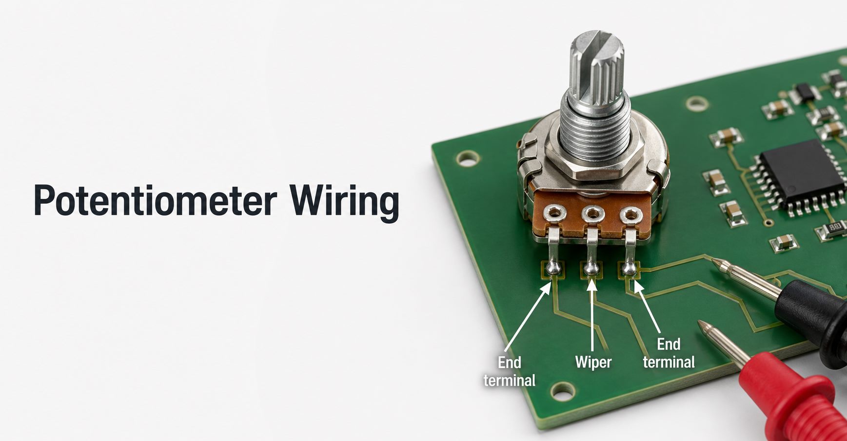
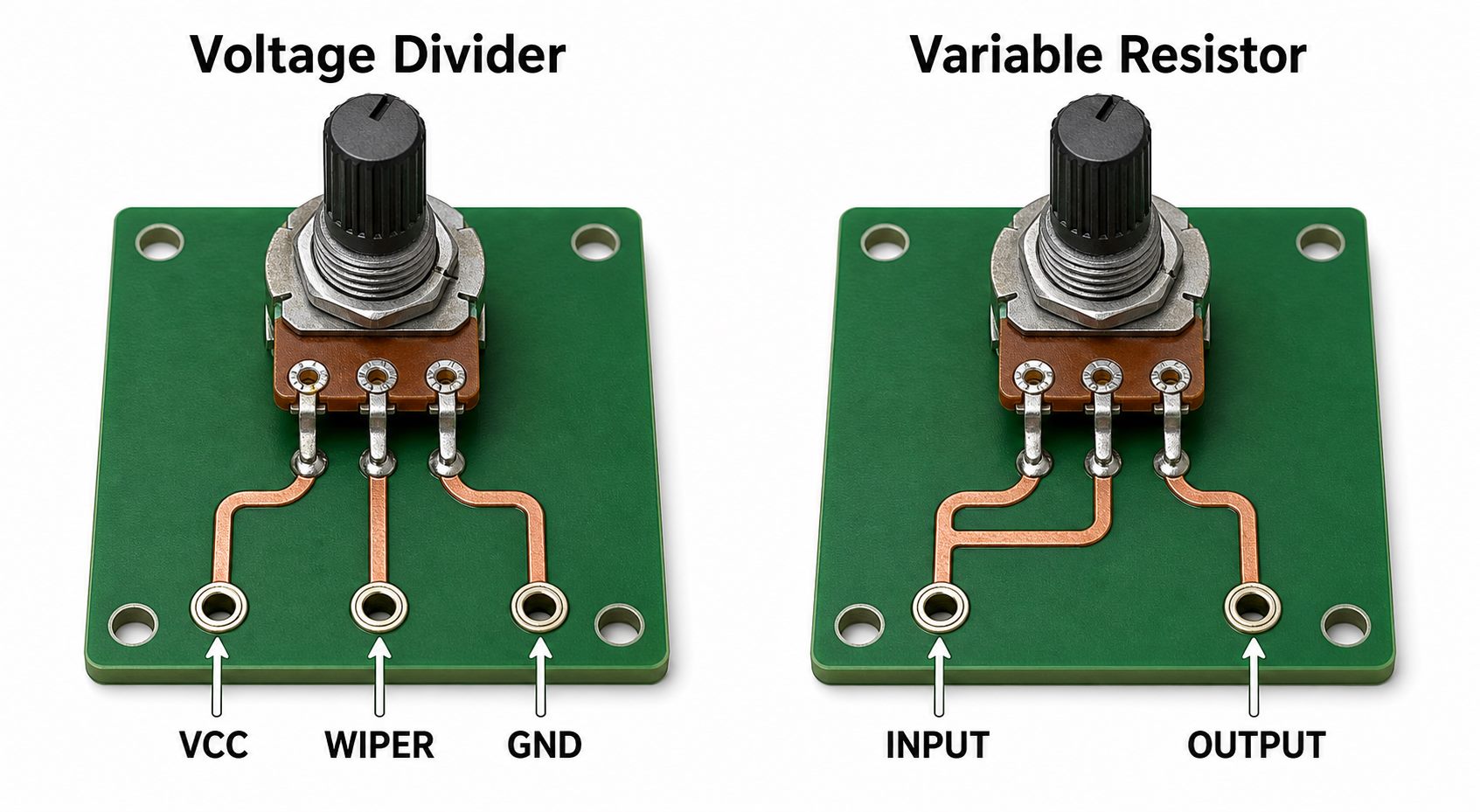
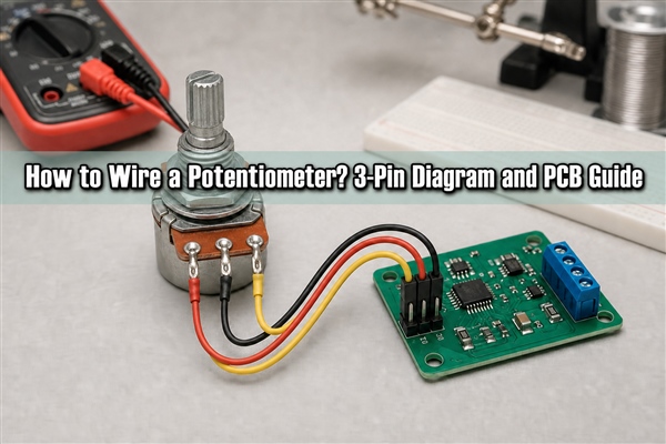
Learning how to wire a potentiometer starts with identifying its two fixed end terminals and movable wiper. A three-wire connection produces an adjustable voltage; a two-wire connection produces an adjustable resistance. The correct choice depends on the circuit function, the potentiometer datasheet, the signal level and the load connected after the wiper.
What Is a Potentiometer and How Does It Work?
A potentiometer is a three-terminal variable resistor. A resistive track runs between the two end terminals, while a movable contact called the wiper travels along that track. Rotating a shaft, moving a slider or turning a trimmer screw changes the resistance from the wiper to each end. The resistance between both end terminals remains approximately equal to the component’s rated value.
There are two basic operating modes. In voltage-divider mode, the circuit uses all three terminals and takes an adjustable output from the wiper. In rheostat mode, the circuit uses the wiper and one end terminal as a two-terminal variable resistance. The component itself has no fixed positive or negative polarity, but the chosen end-terminal connections determine whether clockwise rotation raises or lowers the output.
What Are the Three Wires on a Potentiometer?
The three connections represent two ends of one resistive element and one moving tap. Pin numbers and viewing direction are not universal across every rotary, slide, panel-mount and PCB trimmer package, so use the selected part’s datasheet instead of assuming that a terminal is ground simply because it appears on the left.
| Terminal | Electrical function | Typical voltage-divider connection | What a meter should show |
|---|---|---|---|
| End terminal A | One end of the fixed resistive track | VREF or VIN | Fixed total resistance to end B |
| Wiper | Movable contact on the track | VOUT or ADC input | Resistance changes to either end as the shaft moves |
| End terminal B | Opposite end of the fixed resistive track | GND or signal return | Fixed total resistance to end A |
Some potentiometers also have metal mounting tabs, a body ground terminal, an integrated switch or multiple gangs. These extra connections are not part of the basic three-terminal resistive element. Treat them according to the package drawing and schematic, not by physical resemblance.
How Do You Identify the Wiper and End Terminals?
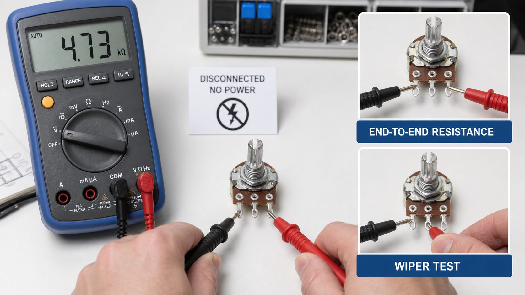
Disconnect the component from power and, where possible, test it outside the circuit. Set a multimeter to resistance mode. The pair that reads approximately the rated resistance and barely changes as the shaft turns identifies the two end terminals. The remaining terminal is the wiper.
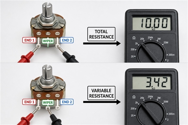
Next, measure between the wiper and either end. The reading should change smoothly from near the contact resistance toward the total resistance. Repeat the measurement from the wiper to the other end; one reading should rise while the other falls. Intermittent jumps, open readings or dead regions can indicate contamination, a damaged track, a worn wiper or unreliable probe contact.
Physical pin 2 is often the wiper on common three-pin rotary parts, but that convention is not sufficient for production documentation. Confirm the terminal numbering, top-view or bottom-view orientation, footprint pad mapping and shaft rotation direction from the exact manufacturer datasheet.
How to Wire a Potentiometer as a Voltage Divider?
Connect one fixed end to the upper reference voltage, connect the opposite end to the return or ground reference, and connect the wiper to the high-impedance input that requires an adjustable voltage. With an unloaded linear potentiometer, the wiper voltage follows its fractional position along the resistive track.
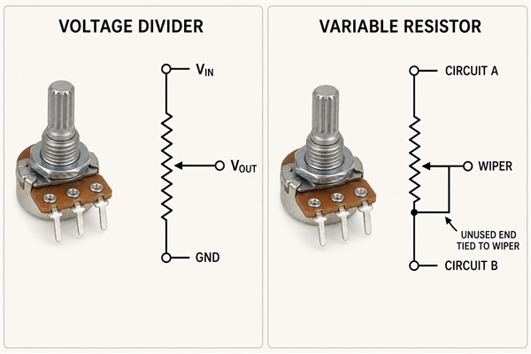
The ideal relationship is VOUT = VIN × RLOW / RTOTAL, where RLOW is the resistance from the wiper to the ground-side terminal. The connected load must be much higher than the potentiometer’s output resistance, or it will change the divider ratio. A buffer amplifier is appropriate when the next stage draws enough current to disturb the setting.
- Verify the maximum voltage across the two end terminals.
- Connect the reference and return to the two fixed ends.
- Connect the wiper to the receiving circuit, not directly to a high-current load.
- Power the circuit and measure the wiper at both rotation limits before connecting sensitive downstream hardware.
- Swap the two end connections if the control direction is opposite to the intended user action.
How to Wire a Potentiometer as a Variable Resistor?
For rheostat operation, place the wiper and one end terminal in series with the circuit. Resistance between those two terminals changes with shaft position. The other end can remain open, but connecting it to the wiper is a common reliability measure: if the moving contact becomes momentarily intermittent, the circuit retains a path through the remaining track instead of depending only on an open wiper contact.
Check the track power rating and maximum wiper current. Using only part of the resistive element does not allow the full rated power to be concentrated into that shorter section. A small panel potentiometer is normally intended for signal control, calibration or bias adjustment, not direct motor, heater, lamp or speaker current. Add a fixed series resistor when the adjustment could otherwise reach an unsafe near-zero resistance.
Does It Matter Which Way a Potentiometer Goes?
Electrically, the two end terminals are interchangeable. Reversing them reverses the relationship between shaft direction and wiper voltage. For a front-panel level control, designers usually expect clockwise rotation to increase the value. Verify that behavior from the actual shaft side because a rear-view terminal drawing can make clockwise and counterclockwise labels appear reversed.
The wiper is not interchangeable with an end terminal. If the circuit takes its output from an end instead of the wiper, rotation will not create the intended adjustable voltage. A schematic should label the nets by function, such as VREF, POT_WIPER and AGND, while the footprint and assembly drawing preserve the manufacturer’s pin numbers.
How to Wire a Potentiometer to an Arduino or MCU ADC?
Use the potentiometer as a voltage divider: connect the two ends to the ADC reference supply and its associated ground, then connect the wiper to an analog input. This keeps the wiper within the permitted ADC input range as long as the reference connections and device limits are correct.
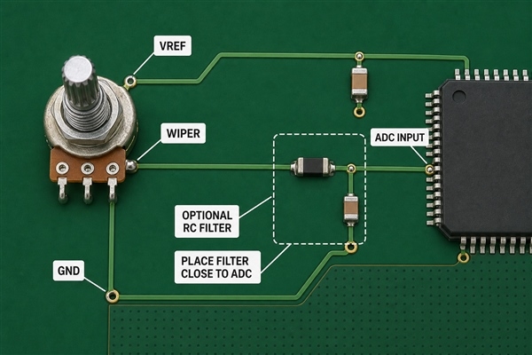
The total resistance must satisfy both loading and ADC acquisition requirements. A lower value draws more continuous current across the reference. A very high value reduces that current but raises source impedance, which can prevent the ADC sample capacitor from settling within its acquisition time. Many general control interfaces use a value around 10 kΩ, but the correct limit comes from the MCU datasheet and sampling configuration.
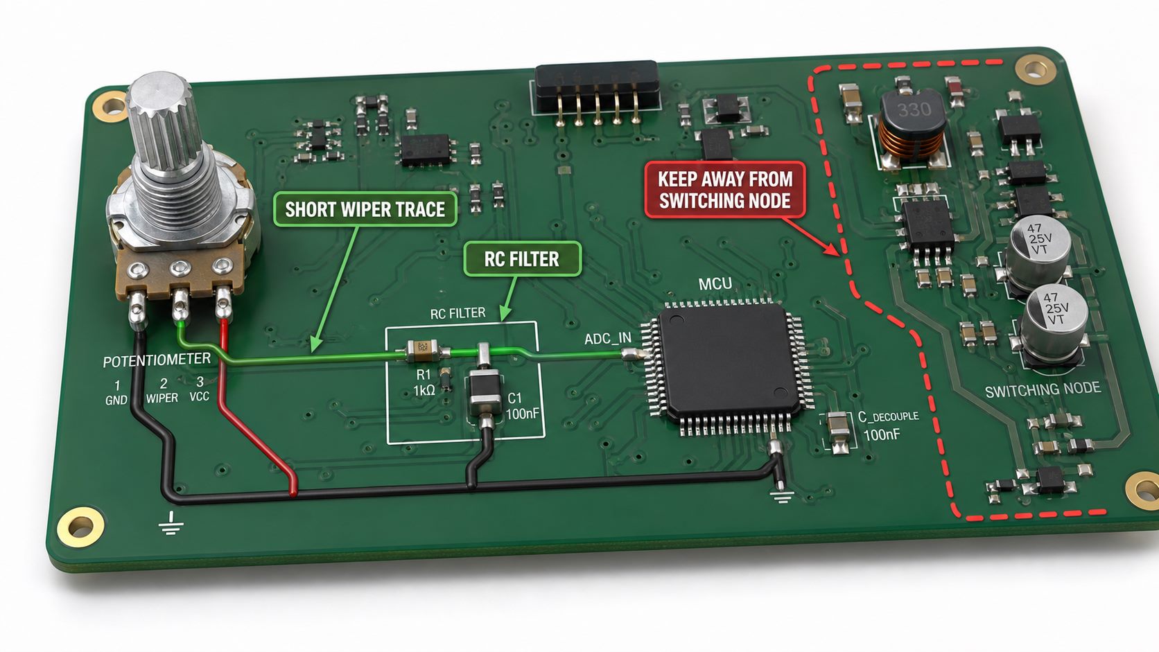
When readings are noisy, place a small RC filter close to the ADC input, keep the wiper route short, and return the potentiometer ground to the quiet analog reference area. The series resistance, capacitor and sampling rate must be selected together so that filtering does not make the control unacceptably slow. Software averaging can reduce random variation, but it cannot repair a floating ground, worn track or incorrect pin mapping.
How to Wire a Potentiometer for Volume Control?
For a basic single-channel passive volume control, connect the audio source to one end terminal, signal ground to the opposite end, and the wiper to the amplifier input. This attenuates the source before amplification. Swapping the two end terminals reverses the direction of level change.
Audio controls commonly use a logarithmic or audio taper because human loudness perception is not linear. Confirm the taper code from the datasheet; letter conventions can differ by manufacturer or region. The potentiometer value must work with the source impedance, amplifier input impedance and coupling capacitors so it does not cause excessive loading, bass roll-off or noise pickup. Stereo audio requires a dual-gang part with matched sections, not two unrelated single controls.
How to Wire a Potentiometer to Control Motor Speed?
Do not place a low-power signal potentiometer directly in series with a motor unless both its current and power ratings explicitly support that load. Motor current, startup surge and inductive transients can overheat the resistive track or damage the wiper.
Instead, wire the potentiometer as a voltage divider that feeds the control input of a PWM motor controller, driver IC, VFD analog input or microcontroller ADC. For a VFD, verify the specified reference voltage, analog-input impedance, common terminal and shielding instructions. For a DC motor driver, keep the low-level wiper signal away from switched motor currents and provide the required common reference or isolation.
How Do You Choose Resistance, Taper, and Power Rating?
Selection begins with the electrical function, then the receiving circuit and mechanical package. The table summarizes the decision points without assuming one universal value.
| Parameter | Choose based on | Practical check |
|---|---|---|
| Total resistance | Allowed reference current, source loading and input impedance | Confirm ADC acquisition or amplifier loading at worst case |
| Taper | Linear control, audio perception or a specified custom response | Read the manufacturer curve and taper code |
| Power rating | Voltage across the track and used track length | Calculate dissipation and apply datasheet derating |
| Wiper current | Current taken by the connected node | Do not treat the wiper as a load-power terminal |
| Rotation and life | User travel, adjustment resolution and operating cycles | Check electrical angle, mechanical angle and rotational life |
| Environmental sealing | Dust, moisture, cleaning, vibration and temperature | Select open, dust-resistant or sealed construction as required |
A multi-turn trimmer improves adjustment resolution for calibration but is slower to set. A panel-mount rotary control provides direct user access, while an SMD or through-hole trimmer is intended for board-level adjustment. Dual-gang and switched potentiometers add terminals and require a matching symbol and footprint rather than a generic three-pin library part.
How Should a Potentiometer Be Mounted on a PCB?
Use the manufacturer’s recommended footprint and verify whether the drawing is a top view or bottom view. Match pin pitch, finished-hole diameter, pad size, solder-mask opening, body courtyard, shaft position and mechanical mounting tabs. A front-panel control should transfer user torque to a panel bushing, bracket or support tabs instead of relying only on three solder joints.
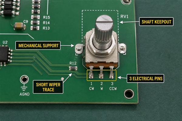
For conventional control boards, FR4 PCB manufacturing can support through-hole panel controls, SMD trimmers and mixed component layouts. Place the control near the board edge when the shaft must pass through an enclosure, but keep adequate copper clearance from mounting hardware and define a shaft or knob keepout in the mechanical model.
An SMD trimmer needs paste apertures and pad geometry matched to its termination design. The SMT stencil should deposit enough solder for stable joints without allowing the part to float or tilt during reflow. Through-hole units require adequate annular rings, lead protrusion control and a soldering process compatible with the body temperature limit.
What PCB Layout Rules Reduce Potentiometer Noise?
Route the wiper as a sensitive analog signal. Keep it short, avoid parallel runs beside clocks, switch nodes and motor phases, and provide a continuous reference path beneath it when the stack-up allows. Connect the ground-side terminal to the same analog reference used by the receiving circuit rather than to a distant noisy return.
- Place any RC filter at the receiving ADC or amplifier input.
- Keep high-current load returns out of the potentiometer ground path.
- Use twisted or shielded cable for a remote panel control when cable length and environment require it.
- Connect a metal case or shield only according to the product and chassis-ground plan.
- Add connector pin labels and test points for VREF, WIPER and GND when service access is needed.
- Define ESD protection when the shaft, knob or remote wiring can expose the interface to user discharge.
EBest Circuit (Best Technology) supports SMT, THT and mixed PCB assembly. Depending on the design risk, inspection can combine 3D SPI, AOI, X-ray, functional testing and final inspection. For a potentiometer interface, a functional test should verify endpoint voltage, smooth travel, direction, channel tracking where applicable and the absence of intermittent output.
How to Test a 3-Wire Potentiometer?
Begin with power removed. Measure between the two end terminals and compare the reading with the marked or specified total resistance. Then measure from the wiper to each end while moving the control through its full travel. The readings should change smoothly in opposite directions and should approximately sum to the total resistance, allowing for contact resistance and tolerance.
After wiring, power the circuit with a current-limited supply. Measure the two reference endpoints, then sweep the wiper and confirm that its voltage remains within the expected range. Check the intended direction, endpoint margin and stability at several positions. The related multimeter guide explains safe voltage, resistance and continuity measurements; never use resistance mode on an energized circuit.
What Potentiometer Wiring Mistakes Cause Reversed or Noisy Output?
Symptoms are easier to diagnose when each failure is tied to a specific connection or physical condition.
| Symptom | Likely cause | Corrective action |
|---|---|---|
| Control works backward | End terminals are reversed | Swap the two fixed-end connections |
| Output is fixed at one rail | Wiper mapped to the wrong pad or shorted | Verify symbol-to-footprint pin mapping and solder bridges |
| Output floats or jumps | Open wiper, missing reference, worn track or poor joint | Check continuity, resolder and replace a damaged part |
| ADC value is unstable | High source impedance, noisy ground or long wiper trace | Review ADC acquisition time, grounding and local filtering |
| Audio crackles | DC on the wiper, contamination or contact wear | Review coupling, clean only with an approved method or replace the control |
| Part overheats | Excessive track power or wiper current | Recalculate dissipation and use a driver or higher-rated component |
The earlier potentiometer wiring guide provides a broader comparison of common wiring configurations. For production hardware, the schematic, footprint, BOM, assembly drawing and test limits must all identify the same terminal numbering and intended rotation.
FAQ About How to Wire a Potentiometer
Can a potentiometer be wired on a breadboard?
Yes. Insert the three electrical pins into separate connected rows, then jumper the two ends to the reference and ground and the wiper to the measured node. Some panel potentiometers have terminals that do not fit a breadboard and need short wires or an adapter PCB.
Can the wiper be connected to either end terminal?
For two-terminal variable-resistor operation, the wiper can work with either end. The chosen end determines whether resistance rises or falls with rotation. Tying the unused end to the wiper can retain a resistive path if wiper contact becomes intermittent.
Can a potentiometer connect directly to a speaker?
A small signal potentiometer is generally unsuitable for direct speaker power. Use it at a high-impedance amplifier input as a volume-control divider, or use a purpose-rated attenuator designed for the speaker impedance and power.
Why does the output not reach exactly zero or the full reference?
Wiper contact resistance, mechanical end stops, loading, protection resistors and ADC reference limits can prevent ideal rail-to-rail travel. Use measured endpoint limits in firmware or calibration rather than assuming perfect 0% and 100% values.
Is a potentiometer the same as a rheostat?
A potentiometer has three accessible terminals and is normally used as a voltage divider. When its wiper and one end are used as two terminals, it performs the variable-resistance function commonly called a rheostat. Power rheostats are often constructed and rated differently from small signal potentiometers.
Conclusion
The practical method for how to wire a potentiometer is to identify the two fixed ends and wiper first, choose voltage-divider or variable-resistor mode, verify direction and power limits, and test the complete interface before relying on it. PCB-mounted controls also need correct footprint orientation, mechanical support, quiet routing and a testable reference path.
EBest Circuit (Best Technology) can support PCB fabrication, SMT/THT assembly and functional verification for control interfaces that use rotary, slide or trimmer potentiometers. For technical communication about a PCB or PCBA design, contact sales@bestpcbs.com.