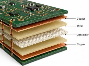
MEGTRON 6 is a Panasonic copper-clad laminate and prepreg system for low-loss, high-speed multilayer PCB projects. It is used when standard FR4 cannot control insertion loss, impedance stability or reflow reliability well enough. This guide explains material properties, Dk/Df values, thermal data, stackup design, applications, material comparisons, cost factors and China source-factory manufacturing support.
What Is MEGTRON 6 PCB Material?
MEGTRON 6 is a Panasonic low-loss PCB material for dense multilayer PCB designs. It is designed for stable signal transmission, strong heat resistance and reliable lamination performance.
Common material references include laminate R-5775 and prepreg R-5670. In PCB production, it is often used for controlled impedance boards, long differential pairs, high-layer-count structures and BGA routing.
MEGTRON 6 is not a general FR4 replacement for every product. It is selected when the project has clear requirements for low dielectric loss, stable Dk and better high-speed PCB reliability.
Why Is Panasonic MEGTRON 6 Used for High-Speed PCB Design?
Panasonic MEGTRON 6 is used to reduce signal loss and improve multilayer PCB stability.
- Lower dielectric loss: Df is lower than many standard FR4 materials, so long signal paths can keep cleaner data transmission.
- Stable impedance support: Stable Dk helps trace width, spacing and dielectric thickness work together more predictably.
- Better insertion loss control: It supports routers, switches, servers, backplanes and communication boards with long differential pairs.
- HDI compatibility: It fits dense BGA escape routing, blind vias, buried vias and high-layer-count PCB structures.
- Heat resistance: High Tg, strong T288 performance and controlled CTE help reduce lamination and reflow reliability risk.
- Smoother copper support: H-VLP copper can reduce conductor loss when the channel loss budget is tight.
MEGTRON 6 Material Properties & Datasheet Overview
The Panasonic datasheet should be checked before stackup approval because values can vary by glass style, copper foil and material version. The main review items are Dk, Df, Tg, CTE, Td, T288, peel strength and thermal conductivity.
| Parameter | Typical Value | Notes |
|---|---|---|
| Dk @ 13GHz | 3.34 / 3.62 | Low Dk glass / normal glass |
| Df @ 13GHz | 0.0037 / 0.0046 | Low Dk glass / normal glass |
| Tg DSC | 185°C | Typical value |
| Tg DMA | 210°C | R-5775(N) model data |
| Td | 410°C | R-5775(N) model data |
| T288 With Copper | >120 min | Typical value |
| CTE Z α1 | 45 ppm/°C | Below Tg |
| CTE Z α2 | 260 ppm/°C | Above Tg |
| Thermal Conductivity | 0.42 W/m·K | R-5775(N) model data |
| Water Absorption | 0.14% | R-5775(N) model data |
| Peel Strength | 0.8 kN/m | 1 oz H-VLP copper |
| Flammability | UL 94V-0 | R-5775(N) model data |
For quoting and production, confirm the exact Panasonic MEGTRON 6 datasheet, material code, copper type, thickness range and stackup before releasing the PCB files.
What Are the Dk and Df Values of MEGTRON 6?
The MEGTRON 6 dielectric constant is about 3.34 to 3.62 at 13GHz, and the Df value is about 0.0037 to 0.0046 at 13GHz. The exact value depends on glass style and material version.
Dk affects impedance and signal speed. Df affects dielectric loss and channel attenuation. Therefore, both values should be used in stackup simulation before routing.
For production, do not copy a generic value into the design without checking the actual laminate and prepreg combination. A small Dk change can affect trace width, spacing, impedance and timing on controlled impedance PCB projects.
What Are the Thermal Conductivity, Tg and CTE of MEGTRON 6?
Thermal conductivity is typically about 0.42 W/m·K, Tg is commonly listed around 185°C by DSC, and Z-axis CTE is about 45 ppm/°C before Tg. These values support reliable multilayer PCB fabrication.
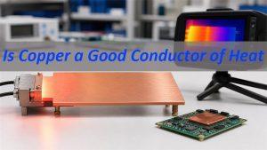
Thermal conductivity helps heat spread through the laminate, although copper planes still carry most heat in many PCB designs. Tg and CTE matter during lamination, reflow and thermal cycling.
High Tg and controlled CTE reduce delamination, barrel cracking and resin stress risk. For thick boards, backplanes and high-layer-count PCB, these values should be reviewed together with copper balance, hole structure and assembly temperature.
How Should a MEGTRON 6 PCB Stackup Be Designed?
The PCB stackup should be built around impedance, insertion loss, layer count and manufacturable dielectric thickness.
- Confirm the signal target first: Define single-ended impedance, differential impedance, frequency range, loss limit and longest trace path.
- Select routing structure: Use microstrip for outer layers, stripline for better shielding and dual stripline only when spacing and loss are acceptable.
- Set dielectric thickness: Match core and prepreg thickness with available Panasonic material instead of using theoretical values only.
- Control copper weight: Keep copper thickness practical for etching accuracy, impedance tolerance and current carrying requirements.
- Keep reference planes continuous: Avoid split-plane crossings under high-speed traces because broken return paths create noise and impedance jumps.
- Balance the copper layout: Keep copper distribution symmetrical across the stackup to reduce bow, twist and lamination stress.
- Plan via structures early: Use through vias, blind vias, buried vias or back drilling based on BGA escape routing and loss budget.
- Add impedance coupons: Place coupons on the production panel so the finished PCB can be measured against the approved stackup.
What Design Factors Affect MEGTRON 6 PCB Performance?
Final PCB performance depends on material selection, layout discipline, copper treatment, via transition and production control.
- Copper roughness: Smoother copper helps reduce conductor loss, especially in long high-speed channels.
- Trace geometry: Trace width, spacing and copper thickness directly affect impedance and insertion loss.
- Via stub length: Long unused via barrels can create resonance and loss, so back drilling may be required.
- Return path quality: A continuous ground reference keeps signal current stable and reduces crosstalk.
- BGA escape routing: Dense fanout can force narrow traces and layer changes, so it should be reviewed before fabrication.
- Solder mask influence: Outer-layer impedance can shift when solder mask thickness and coverage are ignored.
- Glass weave effect: High-speed differential pairs may be affected by glass/resin distribution, so routing angle and spread glass can matter.
- Manufacturing tolerance: Etching, plating, lamination thickness and registration control determine whether the final PCB matches the design.
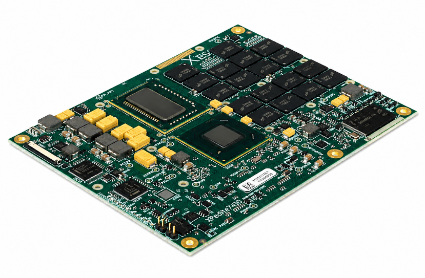
What Applications Commonly Use MEGTRON 6 PCB?
This PCB material is commonly used in electronics that require low loss, stable impedance and reliable multilayer construction. These projects usually include fast signals, dense routing or long transmission paths.
Common applications include:
- Network switches and routers.
- Communication backplanes and line cards.
- Servers, storage systems and computing hardware.
- Wireless base station equipment.
- High-speed connector boards.
- Industrial control and automation PCB.
- Test and measurement instruments.
- Medical diagnostic electronics.
- Aerospace and defense electronics.
- HDI PCB and high-density BGA PCB.
These applications usually choose this laminate when FR4 creates too much signal loss or reliability risk.
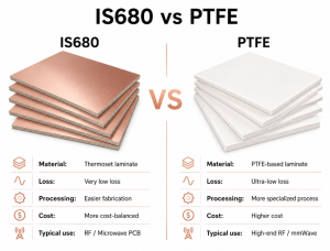
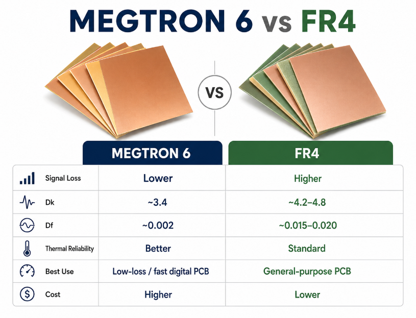
MEGTRON 6 vs FR4: What Is the Difference?
This laminate has lower loss and better high-speed stability than standard FR4, while FR4 has lower cost and wider availability. The choice depends on signal speed, loss budget and product reliability target.
| Item | MEGTRON 6 | FR4 |
|---|---|---|
| Loss Level | Low | Higher |
| Dk Stability | Better | Material-dependent |
| High-Speed Use | Strong | Limited |
| Cost | Higher | Lower |
| Availability | Confirm before production | Very common |
| Best Fit | Servers, routers, backplanes | General electronics |
FR4 is suitable for many ordinary PCB projects. However, when the design includes long differential pairs, strict insertion loss limits or high-layer-count construction, this laminate is often the safer selection.
MEGTRON 4 vs MEGTRON 6: Which Material Should You Choose?
Choose MEGTRON 4 for moderate loss control and this laminate for stricter signal integrity and higher-speed multilayer PCB projects. The decision should be based on channel loss, layer count and budget.
| Item | MEGTRON 4 | MEGTRON 6 |
|---|---|---|
| Loss Level | Medium-low | Low |
| Cost | Lower | Higher |
| Typical Use | Improved PCB designs | Demanding high-speed PCB |
| Stackup Demand | Medium | Higher |
| Suitable Boards | Moderate-speed multilayer PCB | Backplanes, routers, servers |
If the signal path is short and the product cost target is tight, MEGTRON 4 may be enough. If the project has long channels, dense BGA routing or strict loss limits, this grade is usually a better fit.
MEGTRON 6 vs MEGTRON 7 vs MEGTRON 8: How Are They Different?
This grade is a low-loss laminate, while MEGTRON 7 and MEGTRON 8 are aimed at more demanding data-rate and next-generation communication designs. Each grade should be selected by real channel requirements.
| Item | MEGTRON 6 | MEGTRON 7 | MEGTRON 8 |
|---|---|---|---|
| Loss Level | Low | Very low | Advanced low loss |
| Cost Level | High | Higher | Highest |
| Use Range | Servers, routers, backplanes | 5G, large data systems | Advanced communication hardware |
| Selection Logic | Balanced performance and cost | Lower loss demand | Future-facing designs |
Many projects do not require the highest-grade material. A practical review should compare insertion loss target, material lead time, board yield and total project cost before selection.
What Are the Alternative Materials to MEGTRON 6?
Alternative materials should be evaluated by Dk, Df, availability, price, approved vendor list and fabrication yield. They are not automatic replacements unless the customer approves the material change.
| Alternative Material | Main Use | Notes |
|---|---|---|
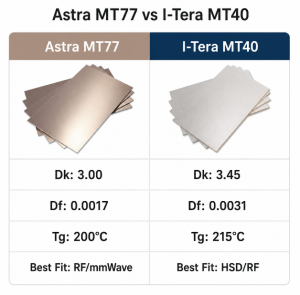
| Isola I-Tera MT40 | Low-loss multilayer PCB | Common comparison material |
| Isola Tachyon 100G | High-speed digital PCB | Strong loss performance |
| Rogers RO4000 Series | RF and mixed signal PCB | More RF-focused |
| Nelco N4000-13 Series | High-speed multilayer PCB | Used in telecom and networking |
| Shengyi Low-Loss Materials | Cost-sensitive projects | Datasheet review required |
Before switching materials, compare dielectric constant, dissipation factor, copper type, Tg, CTE, thickness availability and lamination behavior. For approved products, get written approval before replacing the original Panasonic material.
What Affects MEGTRON 6 PCB Cost?
This PCB cost is affected by the material system, board structure, process difficulty, testing level and delivery plan.
- Material grade: R-5775(N), R-5775(K), R-5775(G) and other versions can differ in availability and price.
- Board size: Larger panels consume more laminate and increase risk of warpage, especially in thick multilayer PCB.
- Layer count: More layers increase lamination time, registration control difficulty and inspection work.
- Copper thickness: Heavy copper or mixed copper weights raise etching and lamination difficulty.
- Via structure: Blind vias, buried vias, stacked vias and back drilling add process steps and inspection cost.
- Impedance tolerance: Tighter tolerance requires more careful stackup control and coupon testing.
- Surface finish: ENIG, ENEPIG and immersion silver have different cost and reliability profiles.
- Testing demand: AOI, X-ray, microsection, impedance test, electrical test and thermal stress test affect the final quote.
- Prototype vs batch order: Small quantities have higher unit cost because setup and material preparation are shared by fewer boards.
- Material lead time: Special thickness, copper type or approved material codes may extend delivery time.
For accurate pricing, provide Gerber files, drill files, stackup, impedance target, surface finish, quantity, inspection requirements and delivery address.
Why Choose EBest as Your MEGTRON 6 PCB Manufacturer?
EBest supports this PCB material manufacturing from China with direct factory communication, stackup review and controlled production for global projects.
- Lower sourcing complexity: One source factory can handle material review, PCB fabrication, testing and export packaging.
- Better manufacturability before production: DFM review helps find stackup gaps, narrow spacing, via risk, copper imbalance and impedance issues before fabrication starts.
- Controlled impedance support: Stackup calculation, production coupons and impedance testing help reduce mismatch between design and finished PCB.
- High-layer PCB experience: Multilayer boards, HDI PCB, BGA routing, back drilling and fine-line fabrication can be reviewed according to project requirements.
- Quality records for shipment: AOI, X-ray, microsection, electrical test and impedance reports can be arranged when required.
- Flexible order support: Prototype, small-batch and mass production projects can be quoted according to files, quantity and material availability.
- Global delivery from China: EBest supports export packaging and international shipment without claiming overseas factories, overseas warehouses or false local branches.
- Clear quotation support: Complete files receive a clearer price, lead time and process review, reducing repeated communication before order release.
FAQs About MEGTRON 6 PCB Material
Q1: Can this material support 112G or higher-speed channels?
A1: It can be used in many demanding digital channels, but the final result depends on trace length, copper roughness, via stubs and connector launch. For 112G-class designs, simulation and insertion loss testing are recommended before mass production.
Q2: Is this material suitable for RF PCB designs?
A2: It can support some RF-related and mixed-signal PCB designs, especially communication hardware with digital and RF sections. However, dedicated RF laminates may perform better in microwave circuits, so the material should match the frequency range and impedance model.
Q3: What density value should be checked?
A3: This material density is usually less important than Dk, Df, Tg, CTE and thermal conductivity for PCB design. Confirm density from the exact Panasonic MEGTRON 6 datasheet, because the value may vary by grade and glass style.
Q4: Can this laminate be used with lead-free assembly?
A4: Yes. Its high Tg and thermal resistance make it suitable for lead-free reflow when the PCB is fabricated and stored correctly. Reflow profiles should still control peak temperature, dwell time and board support to reduce warpage and solder joint stress.
Q5: Does this material require special storage before fabrication?
A5: The laminate and prepreg should be stored under controlled temperature and humidity conditions, with sealed packaging protected from moisture. Moisture control is important because high-layer-count PCB materials can absorb humidity, which may increase lamination or reflow risk.
Q6: What copper foil works well with this material?
A6: Smooth copper foil is often preferred for lower conductor loss, especially when high-frequency signal loss is a concern. Copper roughness affects insertion loss, so the copper type should be included in the stackup review instead of selected after routing.
Q7: Can this laminate and FR4 be mixed in one PCB?
A7: Hybrid stackups are possible, but they require careful review. Different resin systems, Dk values, CTE behavior and lamination flow can affect impedance and reliability, so hybrid construction should be approved before fabrication starts.
Q8: What documents are required for a quote?
A8: A complete quote should include Gerber files, drill files, stackup, board thickness, copper weight, impedance target, surface finish, material request, quantity and test requirements.
Q9: Is this material always better than FR408HR?
A9: Not always. This material usually offers stronger low-loss performance, while FR408HR may work for less demanding designs at a lower cost. The better material depends on signal speed, approved material list, reliability target and total project budget.
Q10: What causes impedance deviation on this type of PCB?
A10: Impedance deviation can come from dielectric thickness variation, copper plating thickness, etching tolerance, glass style, solder mask effect and routing changes. Controlled stackup review and impedance coupons help keep production boards close to design values.
Q11: Can this material be used for rigid-flex PCB?
A11: It is mainly used for rigid multilayer PCB. Rigid-flex projects may require different flexible materials and bonding systems. If a project has rigid-flex sections, the material match, bending area and lamination plan must be reviewed separately.
Q12: How can companies avoid wrong material substitution?
A12: Material risk can be reduced by requesting material confirmation, stackup approval, production records and quality reports when required. The purchase order should clearly state Panasonic MEGTRON 6, exact laminate/prepreg requirements and approved substitutions.
This laminate is a strong material choice when a multilayer PCB must control signal loss, impedance stability and thermal reliability better than standard FR4. The best result comes from a clear stackup, verified Panasonic material, controlled copper selection, reliable via design and proper testing before shipment.
If your project requires low-loss PCB fabrication, high speed PCB or high-layer-count production, EBest can review your files and provide a practical manufacturing quote. Send Gerber files, stackup, quantity and test requirements to sales@bestpcbs.com for a PCB quotation.