





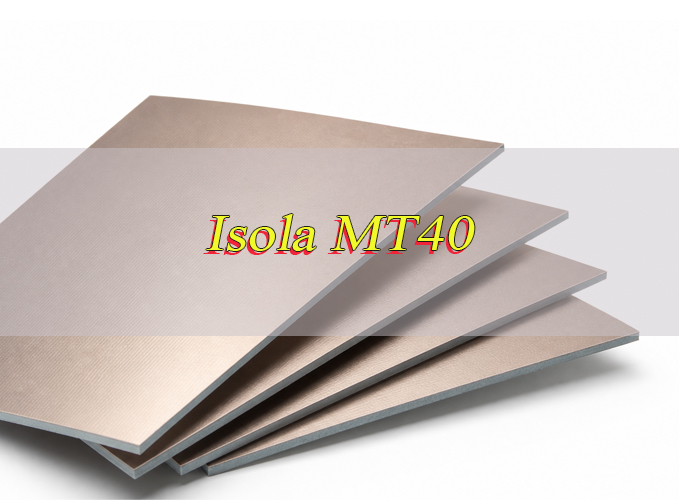
Isola MT40 is a very low-loss laminate and prepreg material for high-speed digital and RF/microwave PCB designs. Its typical Dk of 3.45, Df of 0.0031 and DSC Tg of 215°C support controlled impedance, long signal channels and complex multilayer PCB structures.
Material selection cannot stop at the headline values in an Isola MT40 datasheet. Laminate thickness, prepreg construction, copper profile and finished dielectric spacing all affect channel loss and impedance. A reliable high-speed PCB design starts by matching the material system to the complete stackup.
What Is Isola MT40 PCB Material?
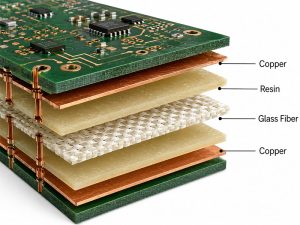
Isola MT40, officially known as I-Tera MT40, is a glass-reinforced very low-loss laminate and prepreg system for high-speed digital and RF/microwave PCB designs. It combines stable electrical performance with fabrication methods compatible with established FR-4 processes.
The material is available in laminate and prepreg forms for double-sided, multilayer and hybrid PCB structures. It is CAF resistant, compatible with lead-free assembly and suitable for multiple reflow and lamination cycles.
Unlike many PTFE-based microwave materials, I-Tera MT40 does not require special through-hole treatments commonly associated with PTFE processing. The result is a low-loss material that fits practical multilayer PCB production without adding unnecessary fabrication complexity.
Why Is Isola I-Tera MT40 Used for High-Speed PCB Designs?
High-speed channels become more sensitive to dielectric loss as frequency and transmission distance increase. Isola I-Tera MT40 has a typical Df of 0.0031, helping reduce the dielectric contribution to insertion loss in long or loss-sensitive signal paths.
Its main advantages include:
- Very low dielectric loss: Supports longer high-speed transmission channels.
- Stable dielectric properties: Improves impedance and propagation-delay predictability.
- Low moisture absorption: The typical value is 0.1%.
- Multilayer compatibility: Laminate and prepreg forms support complex stackups.
- Multiple lamination capability: Suitable for advanced multilayer PCB structures.
- FR-4 process compatibility: Avoids many special PTFE fabrication procedures.
For this reason, Isola MT40 is often considered when standard FR-4 creates too much channel loss but a PTFE-based material system would add unnecessary processing complexity.
Isola MT40 Material Properties & Datasheet Overview
The Isola MT40 datasheet covers electrical, thermal and mechanical performance. Its main values include Dk 3.45, Df 0.0031, DSC Tg 215°C, Td 360°C and thermal conductivity of 0.61 W/m·K.
| Property | Typical Value |
|---|---|
| Tg, DSC | 215°C |
| Tg, DMA | 230°C |
| Tg, TMA | 210°C |
| Td, 5% Weight Loss | 360°C |
| T260 | >60 min |
| T288 | >60 min |
| Z-Axis CTE, Pre-Tg | 55 ppm/°C |
| Z-Axis CTE, Post-Tg | 290 ppm/°C |
| Z-Axis Expansion, 50–260°C | 2.8% |
| X/Y-Axis CTE, Pre-Tg | 12 ppm/°C |
| Thermal Conductivity | 0.61 W/m·K |
| Thermal Stress, Unetched | Pass, 10 sec @ 288°C |
| Thermal Stress, Etched | Pass, 10 sec @ 288°C |
| Dk @ 2/5/10 GHz | 3.45 |
| Df @ 2/5/10 GHz | 0.0031 |
| Volume Resistivity | 1.33 × 10⁷ MΩ-cm |
| Surface Resistivity | 1.33 × 10⁵ MΩ |
| Dielectric Breakdown | 45.4 kV |
| Arc Resistance | 139 sec |
| Electric Strength | 45 kV/mm (1133 V/mil) |
| CTI | Class 3 |
| Peel Strength, 1 oz EDC | 1.0 N/mm (5.7 lb/in) |
| Flexural Strength, Length | 490 MPa (71.0 kpsi) |
| Flexural Strength, Cross | 400 MPa (58.0 kpsi) |
| Tensile Strength, Length | 269 MPa (39.0 kpsi) |
| Tensile Strength, Cross | 241 MPa (35.0 kpsi) |
| Young’s Modulus, Length | 3060 ksi |
| Young’s Modulus, Cross | 2784 ksi |
| Poisson’s Ratio, Length | 0.234 |
| Poisson’s Ratio, Cross | 0.222 |
| Moisture Absorption | 0.1% |
| Flammability | V-0 |
| RTI | 130°C |
These figures are typical material values rather than guaranteed finished PCB results. High-speed PCB modeling must also account for the actual dielectric construction, copper profile, finished thickness and transmission-line geometry. Below is a Isola MT40 datasheet pdf for your reference:
What Are the Dielectric Constant and Dissipation Factor of Isola MT40?
The typical Isola MT40 dielectric constant is 3.45 at 2, 5 and 10 GHz. Its typical dissipation factor is 0.0031 at the same listed frequencies. Dk affects signal velocity and impedance, while Df indicates dielectric signal loss.
Low Df becomes increasingly important as channel frequency and routing length rise. Stable Dk behavior also makes transmission-line geometry and electrical delay easier to predict during PCB design.
In a production stackup, nominal datasheet data is only the starting point. Finished copper thickness, dielectric spacing and the selected construction must be included in the impedance model before trace widths and differential spacing are released.
What Are the CTE Values of Isola MT40?
Isola MT40 has a typical Z-axis CTE of 55 ppm/°C below Tg and 290 ppm/°C above Tg. The X/Y-axis CTE below Tg is 12 ppm/°C, while total Z-axis expansion from 50°C to 260°C is 2.8%.
CTE matters because copper and dielectric materials expand at different rates during lamination, reflow and thermal cycling. Excessive Z-axis movement can increase mechanical stress inside plated through-hole barrels.
These values reduce material-related expansion concerns, but via aspect ratio, plating thickness and repeated reflow cycles still influence plated-hole reliability. Review CTE alongside the complete PCB construction rather than treating it as an isolated material value.
What Are the Tg and Td Values of Isola MT40?
Isola MT40 has a Tg of 215°C by DSC, 230°C by DMA and 210°C by TMA. Its Td is 360°C at 5% weight loss.
Tg describes the temperature region where the resin system changes from a rigid glass-like condition to a more flexible state. Once the material moves above Tg, Z-axis expansion increases and can place more stress on multilayer PCB structures.
Td describes thermal decomposition and should not be confused with Tg. The datasheet also lists T260 and T288 values above 60 minutes and passing thermal stress results at 288°C for 10 seconds.
Together, these values show strong thermal performance for demanding lead-free assembly cycles when the reflow process is properly controlled.
What Is the Thermal Conductivity of Isola MT40?
The typical thermal conductivity of Isola MT40 is 0.61 W/m·K. This value describes heat transfer through the dielectric, but I-Tera MT40 is designed primarily as a very low-loss signal material rather than a dedicated thermal management laminate.
High-speed processors, FPGAs, RF devices and power circuits can still create concentrated hot spots. The PCB must provide additional heat-spreading and heat-removal paths instead of relying on laminate thermal conductivity alone.
Common thermal design methods include:
- Solid copper planes to spread heat across a larger PCB area.
- Thermal via arrays to transfer heat between copper layers.
- Large thermal pads beneath high-power packages.
- Adequate copper weight for current and heat distribution.
- Heatsink contact areas for high-power ICs and modules.
- Chassis conduction paths to transfer heat into the enclosure.
- Controlled airflow for assemblies with continuous high thermal loads.
Copper distribution, thermal vias and the mechanical cooling path often have a greater effect on finished PCB temperature than the laminate thermal conductivity value alone.
What Isola MT40 Laminate Thickness Options Are Available?
The standard Isola MT40 laminate offering covers 2 to 24 mil, equivalent to approximately 0.05 to 0.61 mm. This is the standard laminate thickness range listed for I-Tera MT40.
| Option | Availability |
|---|---|
| Laminate Thickness | 2–24 mil / 0.05–0.61 mm |
| Copper Weight | 1/2, 1 and 2 oz |
| Copper Foil | HVLP, RTF, embedded resistor foil |
| Thinner Copper | Available |
| Heavier Copper | Available |
Standard published copper weights include 1/2 oz, 1 oz and 2 oz, approximately 18, 35 and 70 µm. Thinner and heavier copper foil options are also listed as available.
Thin dielectric structures can provide tighter signal-to-reference-plane coupling, while thicker laminate may help build overall PCB thickness. Confirm the available construction before freezing the production stackup, especially when impedance depends on a narrow dielectric spacing tolerance.
What Isola MT40 Prepreg Options Are Available?
Isola MT40 is available in prepreg form for multilayer PCB lamination. The current datasheet identifies prepreg panel tooling, moisture barrier packaging and available glass fabric categories rather than publishing a fixed construction table with resin content and pressed thickness.
| Prepreg Item | Availability |
|---|---|
| Material Form | Prepreg |
| Panel Tooling | Available |
| Packaging | Moisture barrier packaging |
| Glass Fabric | E-glass |
| Fabric Styles | Square weave; mechanically spread glass |
The exact Isola MT40 prepreg construction needs to match the PCB stackup. Resin content, glass fabric and pressed dielectric spacing can affect resin filling and controlled impedance.
In practice, do not copy prepreg thickness from another material family or substitute a construction because the nominal thickness looks similar. Confirm the available I-Tera MT40 prepreg before the impedance geometry is finalized.
How to Select Isola MT40 Core and Prepreg for Controlled Impedance?
Controlled impedance depends on dielectric spacing, Dk, trace geometry, copper thickness and the reference-plane structure. The exact Isola MT40 core and prepreg arrangement should be fixed before final routing dimensions are released.
- Start with the impedance target. Define 50 Ω single-ended, 90 Ω differential, 100 Ω differential or another required value for each controlled signal group.
- Assign the reference plane first. Keep high-speed signals next to a continuous ground or suitable power plane. Avoid plane splits beneath critical channels.
- Confirm the dielectric spacing. Use the actual core or pressed prepreg thickness planned for production. A small spacing change can shift impedance even when the material grade remains unchanged.
- Use the correct dielectric data. The nominal Isola MT40 Dk is a useful reference, but the production construction and modeling method must match the finished PCB stackup.
- Include finished copper thickness. Outer-layer plating changes the final trace cross-section and can affect impedance. Do not calculate geometry from base copper alone.
- Review the copper profile. HVLP copper can help reduce conductor loss in high-frequency channels where copper surface roughness becomes significant.
- Check resin filling around dense copper. Large copper-density differences can affect pressed dielectric geometry and create local stackup variation.
- Calculate with a field solver. Model microstrip, stripline and differential structures using actual production values rather than a generic online calculator.
- Verify the finished PCB. Use impedance coupons and compare measured results with the approved tolerance before volume production.
In practical stackup review, dielectric spacing is one of the first values to freeze. Changing the prepreg or core geometry after routing is complete may require the controlled traces to be recalculated.
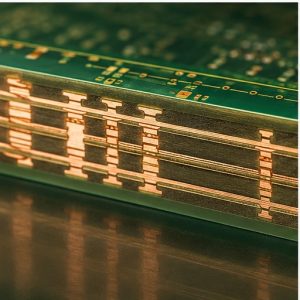
How to Design an Isola MT40 PCB Stackup?
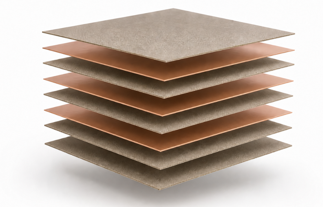
A good Isola MT40 PCB stackup keeps loss-sensitive signals close to continuous reference planes, controls dielectric geometry and maintains a balanced multilayer structure. Layer functions should be assigned before the exact core and prepreg arrangement is finalized.
- Identify critical signal channels. Place PCIe, Ethernet, SerDes and other loss-sensitive interfaces on layers with short, predictable return-current paths.
- Place ground planes beside high-speed layers. Closely coupled signal and ground layers improve return-path control and help reduce electromagnetic interference.
- Separate high-speed signals from noisy power sections. Keep switching regulators and high-current return paths away from sensitive channel routing where possible.
- Select dielectric spacing for impedance. Choose core and prepreg geometry based on target impedance, trace width and manufacturable spacing.
- Use low-profile copper where channel loss matters. Copper roughness contributes to conductor loss, especially as operating frequency increases.
- Control reference-plane transitions. Add suitable ground return vias near signal-layer transitions so return current does not take a long detour.
- Review via stubs on long channels. Back drilling or an alternative via structure may be useful when via stub resonance affects the channel-loss budget.
- Keep the stackup mechanically balanced. Review dielectric distribution, copper density and plane placement on both sides of the PCB centerline.
- Check resin fill and copper balance. Thin dielectric layers are not automatically better. Dense copper patterns and large copper-free areas can create lamination and thickness-control challenges.
- Freeze the stackup before final routing release. Confirm the material construction, finished copper and impedance model before production data is approved.
For example, an 8-layer high-speed PCB may use:
| Layer | Function |
|---|---|
| L1 | Signal |
| L2 | Ground |
| L3 | High-Speed Signal |
| L4 | Power |
| L5 | Ground |
| L6 | High-Speed Signal |
| L7 | Ground |
| L8 | Signal |
This is a functional layer example, not a universal Isola MT40 stackup. The final dielectric thickness and trace geometry must be calculated for the actual impedance and channel-loss requirements.
How Does Isola MT40 Compare with Other Low-Loss PCB Materials?
Isola MT40 sits between conventional high-speed FR-4 systems and more specialized ultra-low-loss or RF-focused materials. Material selection should follow the channel-loss target, operating frequency, stackup complexity and fabrication requirements rather than Dk alone.
| Material | Dk | Df | Main Position | Best Fit |
|---|---|---|---|---|
| Isola MT40 | 3.45 | 0.0031 | Very low loss | High-speed digital, mixed RF/HSD multilayer PCB |
| Tachyon 100G | 3.02 | 0.0021 | Ultra-low loss | Very high-speed digital and long channels |
| Astra MT77 | 3.00 | 0.0017 | Ultra-low-loss RF/MW | RF, microwave and mmWave circuits |
| Rogers RO4350B | 3.48 ± 0.05 | 0.0037 @ 10 GHz | High-frequency RF | RF amplifiers and microwave circuits |
| MEGTRON 6 R-5775(N) | 3.34 @ 13 GHz | 0.0037 @ 13 GHz | Ultra-low-loss multilayer | Networking and high-layer-count ICT PCB |
The published electrical values are not always measured with identical methods or frequencies. This table is best used to understand material positioning rather than as a direct loss ranking.
Choose Isola MT40 when very low loss, laminate-and-prepreg availability and practical multilayer PCB processing are all important. Tachyon 100G may suit a tighter digital channel-loss budget, while Astra MT77 and RO4350B are more strongly aligned with dedicated RF or microwave designs.
MEGTRON 6 is commonly positioned for high-speed multilayer infrastructure hardware. The final material decision should be based on channel modeling, stackup construction and production requirements rather than one Dk or Df value.
What Applications Commonly Use Isola MT40 PCB Material?
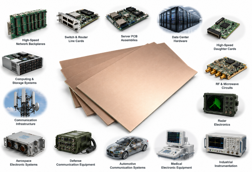
Isola MT40 PCB material is used where high data rates, long transmission channels or RF frequencies make dielectric loss a design concern. Its very low-loss electrical performance and multilayer compatibility are particularly valuable in complex high-speed PCB systems.
Typical applications include:
- High-speed network backplanes
- Switch and router line cards
- Server PCB assemblies
- Data center hardware
- High-speed daughter cards
- Computing and storage systems
- Communication infrastructure
- RF and microwave circuits
- Radar electronics
- Aerospace electronic systems
- Defense communication equipment
- Automotive communication systems
- Medical electronic equipment
- Industrial instrumentation
Isola MT40 is most valuable in high-speed digital, communication and mixed-signal PCB designs where conventional FR-4 creates excessive channel loss but the project still benefits from a glass-reinforced multilayer material system.
FAQs About Isola MT40 PCB Material
Q1: Is Isola MT40 RoHS compliant?
A1: Yes. I-Tera MT40 is identified as RoHS compliant. Final PCBA compliance still depends on the surface finish, solder, electronic components and all other materials used in the completed assembly.
Q2: Is Isola MT40 UL recognized?
A2: Yes. The product data lists UL File Number E41625. I-Tera MT40 laminate and laminated prepreg also have a UL 94 V-0 rating and a relative thermal index of 130°C.
Q3: Is Isola MT40 resistant to CAF failure?
A3: Yes. Isola lists I-Tera MT40 as CAF resistant. Final CAF reliability also depends on conductor spacing, hole spacing, contamination, moisture exposure and the quality of the PCB fabrication process.
Q4: Can Isola MT40 handle multiple PCB reflow cycles?
A4: Yes. The material is identified as multiple reflow capable and lead-free assembly compatible. Its published T260 and T288 values are both greater than 60 minutes, although component temperature limits still affect the final PCBA profile.
Q5: Can Isola MT40 support multiple lamination cycles?
A5: Yes. Multiple lamination cycles are listed among the material’s processing advantages. Advanced multilayer builds still need controlled registration, dielectric geometry and thermal exposure through each press cycle.
Q6: Does Isola MT40 require PTFE-style through-hole treatment?
A6: No. I-Tera MT40 does not require the special through-hole treatments commonly used for PTFE-based laminates. FR-4-compatible PCB processes can be used, although drilling and hole preparation still require controlled parameters.
Q7: What copper foil types are available for Isola MT40?
A7: Published options include HVLP, RTF and embedded resistor foil. The listed HVLP option has an Rz JIS value of ≤2.5 µm, which is relevant when conductor loss contributes to the channel-loss budget.
Q8: What standard copper weights are listed for Isola MT40?
A8: Standard copper weights include 1/2 oz, 1 oz and 2 oz, approximately 18, 35 and 70 µm. The product data also states that thinner and heavier copper foil options are available.
Q9: How much moisture does Isola MT40 absorb?
A9: The typical published moisture absorption is 0.1%. This supports stable material performance, but prepreg and finished PCB materials still require controlled storage and handling during manufacturing and assembly.
Q10: Can Isola MT40 be used in a hybrid multilayer PCB?
A10: Yes. I-Tera MT40 is suitable for hybrid printed circuit designs. Before combining material systems, compare CTE, dielectric properties, resin behavior and lamination compatibility to reduce bonding, warpage and impedance risks.
Q11: How should Isola MT40 be specified on a PCB drawing?
A11: Clearly identify Isola I-Tera MT40 and state whether unapproved material substitution is prohibited. The fabrication drawing should also define finished thickness, copper weight, impedance requirements and any traceability or test-document requirements.
Q12: Can Isola MT40 use embedded resistor foil?
A12: Yes. Embedded resistor foil is listed as an available copper foil option for I-Tera MT40. The resistor material system, target resistance and PCB fabrication process still need to be reviewed for the actual embedded passive design.
Q13: Does low moisture absorption remove the need for material storage control?
A13: No. A typical moisture absorption of 0.1% does not eliminate storage requirements. Prepreg packaging, humidity exposure and material handling can still affect lamination and assembly consistency.
Q14: What files are needed for an Isola MT40 PCB quotation?
A14: Provide Gerber or ODB++, drill files, fabrication drawing, stackup, impedance table, finished thickness, copper weight, surface finish and order quantity. For PCBA production, also include the BOM, centroid data and assembly drawing.
High-speed PCB performance depends on more than choosing a low-loss laminate. Isola MT40 must be matched with the right stackup, dielectric geometry, copper profile and controlled impedance design to deliver stable channel performance from prototype through volume production. Early material and stackup review can also reduce impedance failures, redesigns and avoidable production delays.
Planning a high-speed PCB, multilayer PCB or controlled impedance PCB with Isola MT40? EBest Circuit supports high-speed PCB material review, stackup optimization, controlled impedance, PCB fabrication and PCBA production from our China manufacturing base for global supply. Send your Gerber files and high-speed PCB requirements to EBest Circuit via sales@bestpcbs.com today for an engineering review and quotation.
You may also like


Tags: Isola MT40 datasheet, Isola MT40 dielectric constant, Isola MT40 material properties, Isola MT40 pcb material, Isola MT40 thermal conductivity