A high pin MCU is a microcontroller selected for projects that need many usable I/O pins, multiple communication interfaces, large peripheral mapping flexibility, and stable PCB assembly in compact or function-dense electronics. In practical engineering, the term usually refers to high-pin-count microcontrollers in packages such as LQFP, QFN, BGA, TFBGA, or similar formats, often used in industrial control, automotive electronics, medical devices, smart instruments, communication equipment, robotics, and customized OEM products.
Choosing a high pin MCU is not only about finding the device with the largest number of pins. The real decision involves usable GPIO count, pin multiplexing, ADC channels, PWM outputs, memory size, clock speed, package type, PCB routing density, soldering yield, long-term availability, firmware scalability, and test coverage. Official MCU product selectors commonly include pin count and package filters, which shows how important packaging and I/O planning are during component selection.
What Is a High Pin MCU?
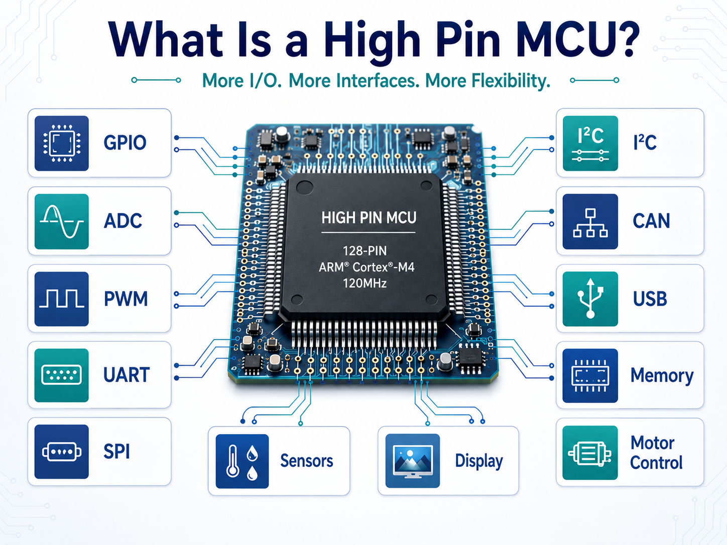
A high pin MCU is a microcontroller with a larger package pin count than entry-level devices, giving designers more physical connections for sensors, displays, buttons, relays, motors, communication buses, memory interfaces, and control signals. In many projects, engineers start considering a high-pin-count MCU when a 32-pin, 48-pin, or 64-pin device cannot support the required number of interfaces without excessive I/O expansion.
There is no single universal threshold for “high pin.” In embedded electronics, 80-pin, 100-pin, 128-pin, 144-pin, 176-pin, and 208-pin MCUs are often treated as higher-pin-count options, depending on the product category. For example, some STM32 families are offered across several package sizes, and one STM32F103 family datasheet describes package options from 36 pins to 100 pins, with peripheral availability depending on the selected device.
Why Does Pin Count Matter in MCU Design?
Pin count affects more than the number of wires connected to the chip. It influences the whole electronic design, including schematic planning, PCB layer count, assembly process, firmware structure, test strategy, and future product upgrades.
A high pin MCU can reduce the need for external I/O expanders, multiplexers, decoders, or secondary controllers. This can simplify firmware timing, reduce bus latency, and improve control precision. It also gives engineers more freedom to separate critical signals, add debug access, reserve spare pins, and support product variants from the same hardware platform.
However, pin count must be reviewed together with the actual available GPIO. Some pins may be shared with oscillator circuits, boot mode settings, reset, power pins, analog references, debug interfaces, or special peripheral functions. A larger package does not always mean every pin is freely available as GPIO. TI engineering support also notes that the number of GPIOs depends on the MCU package, which is a key detail buyers and designers should check before final part approval.
How Does a High Pin MCU Work?
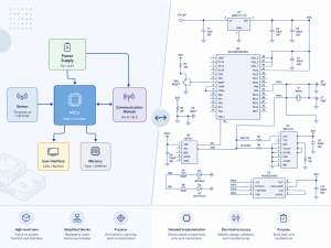
A high pin MCU works like any microcontroller: it integrates a CPU core, memory, timers, communication interfaces, analog blocks, clock circuits, interrupt controllers, and GPIO ports into one programmable device. The difference is that a larger package exposes more of those internal resources to the outside world.
Most MCU pins support multiplexed functions. One physical pin may serve as GPIO, UART TX/RX, SPI signal, I2C line, ADC input, PWM output, timer capture input, CAN signal, Ethernet function, LCD segment, or external memory interface. The firmware configures the selected function through registers or software libraries.
High Pin MCU Package Types
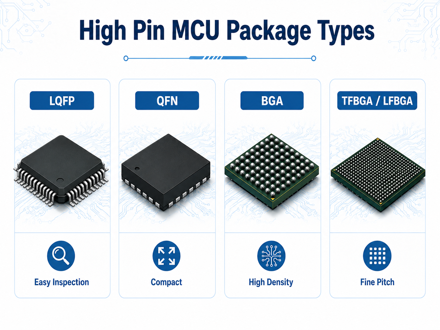
Package selection has a direct impact on PCB design, SMT assembly, inspection, repairability, and product size. For high-pin-count MCUs, the most common package families include LQFP, TQFP, QFN, BGA, TFBGA, and LFBGA. ST’s product families, for example, include package variants such as LQFP and BGA across different pin-count options, while MCU suppliers often provide package-based ordering codes to distinguish pin count and memory configuration.
| Package Type | Common Use | Main Strength | Engineering Consideration |
|---|---|---|---|
| LQFP / TQFP | Industrial control, instruments, automotive modules | Easier visual inspection and rework | Larger PCB footprint |
| QFN | Compact devices, cost-sensitive boards | Small size and good thermal path | Requires accurate stencil and solder control |
| BGA | High-density electronics, advanced products | Strong routing density and compact footprint | Needs X-ray inspection and controlled PCB design |
| TFBGA / LFBGA | Space-limited high-performance products | High pin density in small area | Higher PCB fabrication and assembly control needed |
| WLCSP | Miniaturized consumer or wearable products | Extremely compact | More demanding assembly and board reliability review |
For many industrial and OEM projects, LQFP remains a practical choice because it is easier to inspect, easier to prototype, and friendlier for low-to-mid-volume manufacturing. BGA becomes attractive when the product needs high density, small size, or advanced signal routing.
How Many Pins Does a High Pin MCU Usually Have?
A high pin MCU may have 80, 100, 128, 144, 176, 208, or more package pins. The exact number depends on the MCU family, package type, target application, and peripheral set.
A 100-pin MCU is common in industrial controllers, display modules, motor control boards, and mid-range embedded systems. A 144-pin or 176-pin MCU is often selected when the design needs external memory, LCD control, many timers, parallel interfaces, Ethernet, multiple ADC inputs, or many product-variant options. Larger BGA packages may be used when the product requires higher performance and compact routing.
The important question is not “How many package pins are available?” The better question is “How many pins remain usable after power, ground, boot, reset, debug, oscillator, analog reference, and dedicated peripheral pins are assigned?”
High Pin MCU vs Low Pin MCU: What Is the Difference?
A low pin MCU is suitable for simple control tasks, small sensors, basic power modules, compact IoT nodes, LED drivers, button panels, and cost-sensitive products. A high pin MCU is better for products with many interfaces, complex control logic, multiple sensors, display functions, industrial communication, or expansion requirements.
| Comparison Item | Low Pin MCU | High Pin MCU |
|---|---|---|
| Typical Pin Count | 8–64 pins | 80–208+ pins |
| PCB Size | Smaller | Larger or denser |
| Design Flexibility | Limited | Stronger |
| Peripheral Access | Fewer exposed functions | More exposed functions |
| Firmware Expansion | More constrained | Easier to scale |
| Assembly Difficulty | Lower | Medium to high |
| BOM Cost | Usually lower | Usually higher |
| Best Fit | Simple embedded products | Complex OEM electronics |
A low pin MCU can still be powerful, especially in compact products. A high pin MCU is selected when the product architecture needs more hardware access, not simply because a larger chip looks more advanced.
Key Parameters to Check Before Choosing a High Pin MCU
A reliable MCU selection process starts with the product architecture, not with the part number. Engineers should review the full signal map before approving the MCU.
| Parameter | Why It Matters | What to Check |
|---|---|---|
| Usable GPIO Count | Determines whether all signals can connect directly | Exclude power, ground, reset, oscillator, boot, and debug pins |
| Pin Multiplexing | Prevents function conflicts | Confirm UART, SPI, I2C, CAN, ADC, PWM, USB, Ethernet, and LCD mapping |
| Flash Memory | Supports firmware size and future updates | Leave enough margin for feature expansion |
| RAM | Affects real-time data handling | Check buffers, RTOS, communication stacks, display data |
| ADC / DAC Channels | Important for sensors and analog control | Confirm resolution, sampling speed, reference design |
| Timer / PWM Resources | Needed for motors, LEDs, power control | Check channel quantity and timer grouping |
| Package Type | Affects PCB and assembly | Match PCB supplier and SMT capability |
| Operating Temperature | Important for industrial and automotive use | Review standard and extended temperature grades |
| Lifecycle Status | Reduces sourcing risk | Check active, NRND, EOL, and second-source options |
The best high pin MCU is the one that matches the product’s electrical, mechanical, firmware, supply chain, and production requirements at the same time.
Common Applications of High Pin MCU
High pin MCU devices are widely used in electronics that need many signals and stable embedded control. NXP describes its general-purpose Arm Cortex-M MCU portfolio as covering performance, efficiency, scalability, software tools, and development boards, which reflects how MCU selection is now closely tied to complete project development.
| Application | Why High Pin MCU Is Used |
|---|---|
| Industrial control boards | Handles sensors, relays, displays, communication, alarms, and safety signals |
| Automotive electronics | Supports control modules, lighting control, motor control, sensors, and CAN communication |
| Medical devices | Connects sensors, displays, buttons, alarms, memory, and communication interfaces |
| Smart instruments | Supports LCD, keypad, ADC channels, calibration, and data logging |
| Robotics | Controls motors, encoders, sensors, communication, and safety feedback |
| Energy systems | Manages voltage sensing, current sensing, relays, protection, and communication |
| Communication equipment | Supports control logic, status monitoring, ports, and management interfaces |
| LED control systems | Provides PWM channels, thermal feedback, dimming control, and fault detection |
For OEM and ODM projects, a high pin MCU can support multiple product versions on one hardware platform. This helps reduce redesign work when customers need different interface options.
PCB Design Rules for High Pin MCU Projects
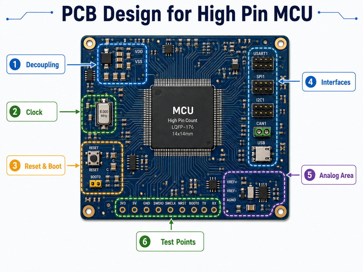
High pin MCU PCB design needs careful planning because more pins usually mean higher routing density, more signal groups, and greater risk of layout congestion. The layout should start from power integrity, clock stability, programming access, and critical signal grouping.
Power and Ground Planning
Place decoupling capacitors close to each MCU power pin. Use short return paths, clean ground reference, and proper power plane design. High-pin-count MCUs often have multiple VDD and VSS pins, and every power group should be treated as part of the system’s reliability foundation.
Clock and Reset Routing
Crystal and clock traces should be short, clean, and protected from noisy switching signals. Reset and boot pins should include stable pull-up or pull-down design according to the MCU datasheet.
Peripheral Grouping
Group related pins logically. Motor control, ADC sensing, communication buses, display signals, and debug interfaces should be arranged to reduce trace crossing and improve testability.
BGA Escape Routing
If the MCU uses BGA packaging, PCB layer count, via-in-pad, microvia, solder mask registration, and X-ray inspection must be reviewed early. BGA packages can improve density, but they also require stronger PCB fabrication and assembly process control.
Reserved Pins
Reserve extra pins when the product roadmap is not fixed. Spare GPIO can support future sensors, new communication functions, production testing, or customer-specific versions.
Manufacturing and Assembly Risks of High Pin MCU
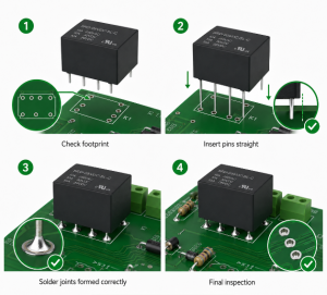
High pin MCU assembly requires accurate solder paste control, component placement, reflow profile management, and post-assembly inspection. For fine-pitch QFP, common process concerns include solder bridging, insufficient solder, lead coplanarity, and alignment. For BGA, hidden solder joints make X-ray inspection important.
IPC-A-610 provides acceptance requirements for electronic assemblies, while IPC J-STD-001 covers requirements for soldered electrical and electronic assemblies. These standards are commonly referenced when defining workmanship, soldering quality, inspection expectations, and production acceptance levels.
Moisture sensitivity also matters. IPC/JEDEC J-STD-020 is used to determine moisture-sensitivity-level classification for surface mount devices so they can be packaged, stored, and handled properly before reflow. This is especially important for high-pin-count ICs exposed to lead-free reflow temperatures.
Testing Methods for High Pin MCU Boards
Testing should be planned before PCB layout is finalized. A complex MCU board without test points can be difficult to debug, inspect, and validate during mass production.
| Test Method | Purpose |
|---|---|
| AOI | Checks visible solder joints, polarity, placement, and obvious defects |
| X-ray | Inspects BGA solder joints, hidden pads, voiding, and internal solder defects |
| ICT | Tests electrical connectivity, shorts, opens, and basic component values |
| Flying Probe | Useful for prototypes and small batches when fixtures are not ready |
| Functional Test | Confirms firmware, I/O behavior, communication, sensor reading, and output control |
| Boundary Scan | Useful when supported by the MCU and connected ICs |
| Programming Test | Verifies firmware loading, boot mode, debug access, and memory response |
| Burn-In / Aging Test | Supports reliability screening for demanding products |
For high pin MCU projects, functional testing should include every important I/O group. A board may pass power-on testing but still fail in the field if one peripheral group is not verified under realistic load.
Common Failure Modes in High Pin MCU Projects
High pin MCU failures often come from system-level mismatches rather than the MCU itself. The most useful review is a combined engineering, PCB, firmware, and production review.
| Failure Mode | Typical Cause | Practical Solution |
|---|---|---|
| Missing GPIO during firmware development | Pin multiplexing conflict | Build a pin assignment table before schematic approval |
| Communication failure | Wrong alternate function, pull-up issue, or layout problem | Validate pin mapping and signal integrity |
| ADC instability | Noisy reference, poor grounding, long analog traces | Separate analog routing and improve filtering |
| Solder bridging | Fine pitch, excessive paste, stencil issue | Optimize stencil aperture and reflow profile |
| BGA open joint | Warpage, poor pad design, placement issue | Use X-ray inspection and controlled PCB stack-up |
| Boot failure | Wrong BOOT pin state or unstable reset | Add correct pull resistors and reset timing review |
| Field reset | Power dip, EMI, watchdog misconfiguration | Improve power integrity and firmware fault handling |
| Sourcing delay | MCU lifecycle or allocation issue | Approve alternatives early and monitor stock risk |
A high pin MCU should not be selected only by schematic needs. It should also be reviewed for manufacturability, testing, and long-term supply.
How to Choose the Right High Pin MCU for Your Project?
The right selection process begins with a complete I/O and peripheral map. Engineers should list every required signal, assign the preferred peripheral function, check package availability, and leave enough margin for future changes.
Step One: Define the Product Architecture
List sensors, outputs, communication interfaces, displays, memory, debug ports, power-control signals, safety signals, and factory test pins.
Step Two: Build a Pin Assignment Table
Create a table that includes signal name, MCU pin, alternate function, voltage level, pull-up/pull-down requirement, test point, and firmware owner.
Step Three: Check Peripheral Conflicts
A high pin MCU may still have conflicts when several functions share the same internal resources. Check timer channels, DMA mapping, ADC groups, communication ports, and interrupt priorities.
Step Four: Review PCB Routing
Confirm whether the selected package can be routed within the planned PCB size and layer count. A lower-cost MCU may increase PCB complexity if the package is too dense or poorly matched to the board.
Step Five: Confirm Supply Chain Status
Check lifecycle, stock, lead time, authorized channels, alternative models, and package compatibility. High pin MCU shortage or EOL risk can affect the whole product schedule.
Step Six: Validate with Prototype Testing
Prototype testing should include firmware, thermal behavior, EMC preparation, programming process, and full I/O verification.
Cost Factors for High Pin MCU Projects
The total cost of a high pin MCU project is not limited to chip price. It includes PCB layer count, assembly yield, inspection method, test fixture, firmware development, procurement risk, and lifecycle management.
| Cost Factor | How It Affects the Project |
|---|---|
| MCU Unit Price | Higher pin count and larger memory usually increase component cost |
| Package Type | BGA and fine-pitch packages may require stronger assembly control |
| PCB Layer Count | More pins can require more routing layers |
| PCB Technology | Microvias, via-in-pad, impedance control, and fine lines increase fabrication cost |
| Test Fixture | More I/O may require more test points and fixture complexity |
| Firmware Work | More peripherals increase configuration and validation time |
| Inspection | BGA packages may require X-ray inspection |
| Supply Chain | Limited stock or long lead time can increase procurement cost |
| Certification | Medical, automotive, and industrial products may need stronger documentation |
A good cost strategy is not always choosing the smallest or cheapest MCU. In many OEM projects, a slightly larger MCU can reduce external components, simplify firmware, improve product scalability, and lower redesign cost.
Procurement Tips for High Pin MCU Buyers
Buyers should evaluate high pin MCU sourcing with both commercial and technical logic. A part may look available during prototype development but become difficult to source when the project moves into batch production.
Before purchase, confirm the exact part number, package code, temperature grade, memory size, packaging method, MSL level, date code, traceability, and compliance documents. For products sold into Europe or other regulated markets, RoHS compliance may be required; the European Commission states that RoHS currently restricts ten substances in electrical and electronic equipment.
Procurement teams should also avoid approving only one MCU model when the product has long lifecycle expectations. A better approach is to prepare at least one compatible alternative, review pin-to-pin migration possibility, and reserve firmware flexibility where possible.
For OEM/ODM programs, early BOM review is valuable. It helps identify high-risk part numbers, long lead time components, end-of-life risk, and possible engineering alternatives before production is delayed.
Quality Control for High Pin MCU Assembly
Quality control starts before SMT production. The engineering team should review the datasheet, footprint, stencil design, PCB finish, reflow profile, handling condition, and inspection standard.
For LQFP or TQFP packages, AOI and visual inspection can verify many solder joint conditions. For QFN and BGA packages, hidden joints require stronger process validation. X-ray inspection is often used for BGA and bottom-terminated components because external visual inspection cannot confirm every solder joint.
Production control should include incoming component verification, MSL management, solder paste inspection, placement accuracy, reflow profiling, AOI, X-ray where needed, programming, and functional testing. For higher-reliability products, traceability records should connect the MCU batch, PCB lot, solder paste batch, production date, operator station, inspection result, firmware version, and shipment record.
What Should Be Checked Before Placing a High Pin MCU Order?
Before placing an order, engineers and buyers should align the technical and commercial requirements in one checklist.
| Checklist Item | Required Review |
|---|---|
| Exact MCU Part Number | Confirm series, memory, package, temperature grade |
| Pin Assignment | Confirm no conflict between GPIO and alternate functions |
| PCB Footprint | Match datasheet land pattern and assembly capability |
| Package Handling | Check MSL, storage, baking, and reflow requirement |
| Firmware Access | Confirm SWD, JTAG, UART boot, or programming method |
| Test Points | Reserve access for key power rails and I/O signals |
| Compliance | Confirm RoHS, REACH, and customer-specific requirements |
| Lifecycle | Check active status, lead time, and alternatives |
| Production Test | Define programming, ICT, functional test, and inspection plan |
| Traceability | Confirm batch record, date code, and inspection documentation |
The safest time to solve MCU risk is before PCB layout is finalized. Once the PCB is already fabricated, every pin conflict becomes more expensive.
FAQs
What does high pin MCU mean?
A high pin MCU means a microcontroller with many package pins and more exposed I/O resources. It is used when a product needs many sensors, outputs, communication interfaces, displays, test points, or future expansion options. The term is practical rather than fixed by one industry standard.
Is a high pin MCU the same as a high GPIO MCU?
Not always. Package pin count and usable GPIO count are related, but they are not identical. Some pins are used for power, ground, reset, oscillator, debug, boot, analog reference, or dedicated functions. Always check the datasheet and build a usable pin table.
When should I choose a 100-pin MCU?
A 100-pin MCU is suitable when 64-pin devices cannot provide enough GPIO, peripheral mapping, ADC channels, PWM outputs, or communication interfaces. It is common in industrial control boards, display control products, smart instruments, and mid-complexity OEM electronics.
When should I choose a 144-pin MCU or larger?
A 144-pin or larger MCU is useful when the product needs external memory, LCD control, Ethernet, many timers, multiple communication buses, or a scalable hardware platform. It is also helpful when one PCB must support several customer-specific versions.
Is BGA better than LQFP for high pin MCU?
BGA is better for compact, high-density routing, but LQFP is easier to inspect, prototype, and rework. For many industrial products, LQFP is practical. For smaller and more advanced electronics, BGA may be the better choice if the factory has proper PCB and X-ray capability.
Does a high pin MCU increase PCB cost?
It can increase PCB cost if the package requires more layers, finer traces, smaller vias, or via-in-pad design. However, it may reduce external components and redesign work. The final cost depends on the whole product architecture, not the MCU alone.
Conclusion
A high pin MCU is the right choice when a product needs many direct connections, flexible peripheral mapping, stable control functions, and enough room for future expansion. The strongest design approach is to check usable GPIO, package type, pin multiplexing, PCB routing, assembly process, test coverage, and supply chain status together.
For engineers, the key selection advice is simple: do not choose by pin count alone. Build a complete signal map, confirm every alternate function, reserve test points, and validate the design through prototype testing. For buyers, the practical procurement advice is to confirm lifecycle, packaging, compliance, traceability, and alternative supply before volume production begins.