





Electronic product development testing is a staged system for proving that a device meets its requirements, survives its intended environment, and can be manufactured repeatedly. A useful plan connects requirements, schematic and PCB reviews, prototype bring-up, EVT, DVT, PVT, compliance work, and production test data instead of treating testing as one final event.
This guide is a practical companion to our Electronic Product Design & Test overview. It focuses on the evidence and exit criteria that hardware teams should establish before releasing a PCB-based product to volume manufacturing.

What Should an Electronic Product Testing Checklist Prove?
A complete checklist should prove five things: the product does the intended job, the design has acceptable margin, foreseeable failure modes are controlled, regulatory work is planned, and the factory can build and test the product consistently.
Start with traceable requirements rather than a list of instruments. Each important requirement needs a verification method, acceptance limit, responsible owner, sample stage, and record location. “The unit powers on” is not an adequate criterion. “The unit starts from the specified input range, reaches its operating state within the defined time, and reports no diagnostic fault” is testable.
| Evidence area | Question answered | Typical record |
| Functional | Does every required function work across normal and boundary conditions? | Requirement-to-test matrix and test report |
| Electrical | Are rails, interfaces, timing, current, and protection behavior within limits? | Waveforms, measurements, and fault-injection results |
| Mechanical and thermal | Does the assembled product fit, cool, and withstand expected loads? | Fit review, thermal map, and environmental results |
| Manufacturing | Can PCB fabrication, assembly, programming, inspection, and rework be repeated? | DFM/DFT review, work instructions, pilot build data |
| Compliance | Is the design prepared for the standards and market requirements that apply? | Compliance plan and accredited-lab reports where required |
| Production quality | Can each unit be screened with stable limits and traceable results? | Fixture validation, limits file, serial-number test log |
How Do Requirements Become Verifiable Test Cases?
Requirements become verifiable when each statement has one meaning, a measurable limit, a defined condition, and an objective pass/fail method. Ambiguous words such as “fast,” “low power,” or “high reliability” should be replaced by product-specific limits.
- Define the use case. Record users, loads, duty cycle, interfaces, installation, abuse cases, and service expectations.
- Set operating boundaries. Specify input range, temperature, humidity, vibration, communication conditions, and expected lifetime assumptions.
- Identify safety and compliance constraints. The target market and product category determine which standards need professional review.
- Write acceptance criteria. Include units, tolerances, test duration, setup, firmware revision, and sample quantity.
- Build a traceability matrix. Link each requirement to design evidence, one or more tests, results, and corrective actions.
Traceability prevents a common release problem: many tests are completed, but nobody can show whether every important requirement was actually covered. It also makes change review faster because an engineering change can be mapped to affected requirements and regression tests.
Which Design Reviews Should Happen Before the First Prototype?
Before prototype fabrication, review the architecture, schematic, PCB layout, BOM, mechanical interfaces, firmware hooks, manufacturability, and test access. Problems found in files are normally easier to correct than problems found after boards, stencils, fixtures, or tooling exist.
- Architecture: power budget, interface partitioning, protection strategy, diagnostic coverage, and upgrade path.
- Schematic: component ratings, unused pins, pull states, reset behavior, decoupling, programming access, and alternate parts.
- PCB layout: return paths, controlled impedance where required, high-current loops, creepage and clearance, thermal paths, antenna keep-outs, and enclosure constraints.
- BOM: exact manufacturer part numbers, lifecycle status, approved alternates, package compatibility, and sourcing risk.
- DFM: board geometry, panelization, footprints, solder-mask openings, stencil needs, assembly clearances, polarity marking, and rework access.
- DFT: test pads, ground references, boundary access, programming connector, fixture datum points, safe test modes, and diagnostic firmware.
Use the manufacturer’s real process capability for the final review. Generic design rules are a starting point; stack-up, materials, copper, tolerances, assembly equipment, inspection access, and fixture strategy must match the chosen production route. Best Technology’s PCB capability information, PCB assembly service, and PCB design tools can support this handoff.
What Are EVT, DVT, and PVT in Hardware Validation?
EVT, DVT, and PVT are progressive validation gates: EVT proves the engineering concept, DVT proves the finished design against requirements, and PVT proves the production process. The exact names and sample quantities vary by company, but the gate logic should remain clear.
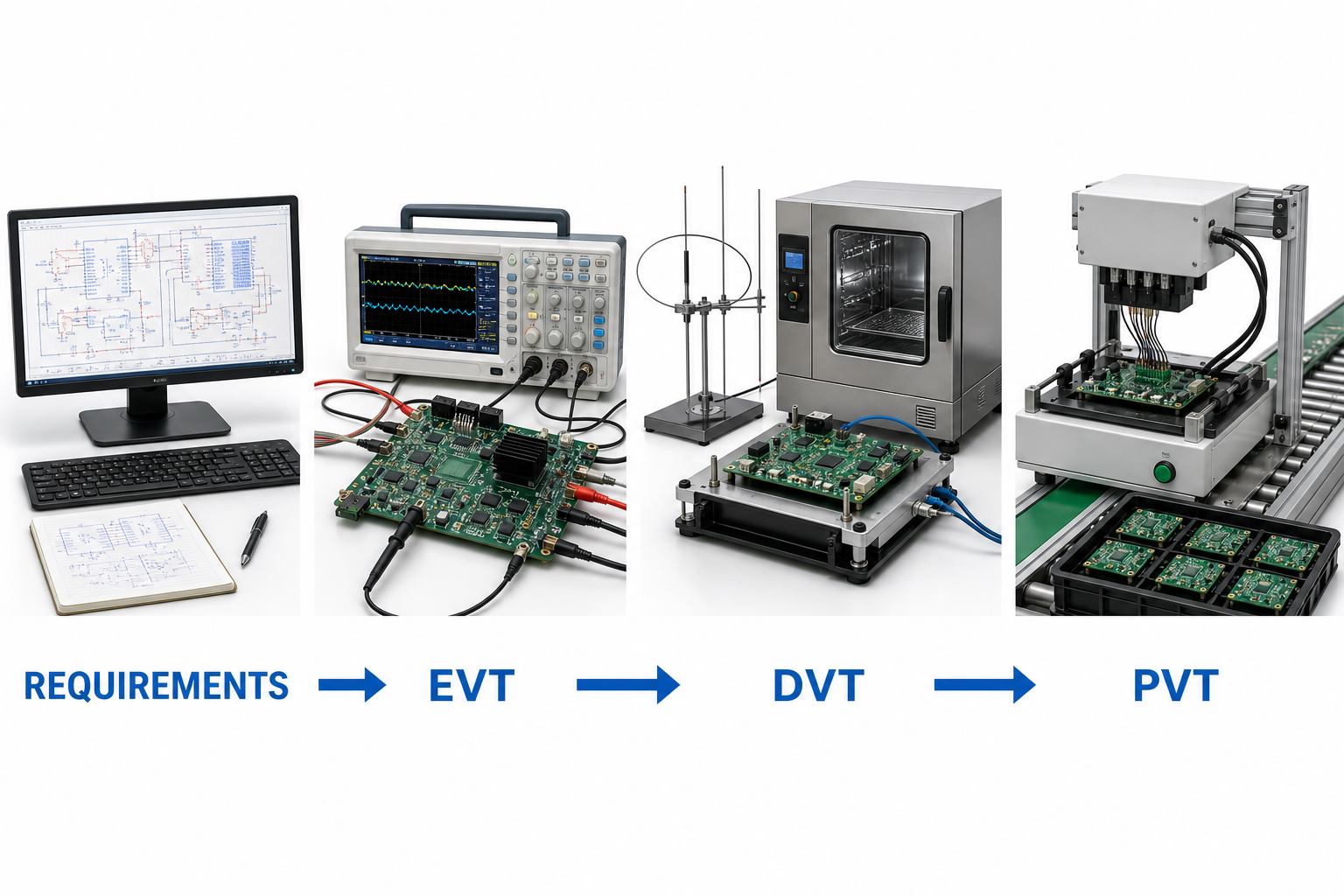
| Gate | Main question | Typical activities | Exit evidence |
| Prototype / bring-up | Can the core circuits and firmware operate? | Rail checks, current-limited power-up, interface debug, first functional tests | Bring-up log and prioritized issue list |
| EVT | Does the engineering design meet core functional and performance targets? | Boundary tests, thermal measurements, signal checks, early EMC checks, design revisions | Core requirements passed and high-risk design issues closed |
| DVT | Does the production-intent design meet the full requirement set? | Mechanical, environmental, reliability, safety, EMC/RF, usability, and regression testing | Design verification report and controlled release candidate |
| PVT | Can the intended line build and test the controlled design repeatedly? | Pilot build, work-instruction trial, fixture validation, operator training, yield analysis | Released process, stable test limits, traceability, and approved deviations |
| Mass production | Does ongoing output remain under control? | Incoming, in-process, functional, final, reliability-monitoring, and change-control activities | Production data, corrective actions, and controlled change history |
Do not advance a stage because a calendar date arrived. Advance when the agreed evidence is complete, critical failures are understood, retesting is finished, and open risks are formally accepted by the responsible team.
How Should Prototype Bring-Up and EVT Be Run?
Prototype bring-up and EVT should move from safe, observable checks to integrated operation. The goal is not to demonstrate one successful unit; it is to understand the design margin, failure behavior, and revisions needed before design verification.
- Confirm board revision, assembly drawing, BOM substitutions, and inspection results.
- Check resistance to ground on key rails before applying power.
- Use current-limited supplies and verify power sequencing, reset, clocks, and programming access.
- Load controlled firmware and record the hardware, firmware, equipment, and test-script versions.
- Test interfaces and core functions individually before full-system operation.
- Measure current, ripple, timing, thermal behavior, signal quality, and fault response at nominal and boundary conditions.
- Run early EMC and thermal pre-checks while layout changes are still practical.
- Convert every failure into a reproducible condition, suspected mechanism, corrective action, and regression test.
Preserve failed units when they provide useful evidence. Replacing a component until the prototype works may restore operation but can erase the root cause. Photograph the board, capture waveforms, record configuration, and compare the failure with a known-good sample before rework.
What Must DVT Prove Before the Design Is Frozen?
DVT must show that the production-intent product satisfies its complete requirement set under realistic operating, environmental, mechanical, and compliance-related conditions. It should use controlled hardware, firmware, enclosure, cable, labeling, and accessories.
The DVT plan commonly covers functional regression, power modes, thermal steady state and cycling, input extremes, ESD and EMC pre-compliance, vibration or drop where relevant, ingress or humidity where relevant, connector endurance, abnormal operation, firmware recovery, and long-duration operation. Product category and destination market determine the actual safety, EMC, radio, environmental, or industry standards; confirm them with a qualified compliance professional or test laboratory.
Define sample allocation before testing. Some tests are destructive or can age the samples, so the same unit should not automatically be reused for unrelated validation. Record serial number, build history, firmware, calibration status, test order, deviations, failures, repairs, and retest outcome. A passing summary without configuration data is weak evidence because it cannot reliably support a later investigation.
How Do DFM and DFT Reduce Production Risk?
DFM reduces variation in fabrication and assembly, while DFT makes faults observable and testable. Together they turn a working prototype into a product that can be built, inspected, programmed, and screened without depending on one expert technician.
For PCB assembly, DFM should review footprints, component orientation, paste apertures, thermal balance, bottom-terminated parts, BGA inspection needs, hand-inserted parts, depanelization stress, cleaning requirements, and rework clearance. Inspection planning should match the fault type: AOI can detect many visible placement and solder defects, while X-ray is useful for hidden joints. Neither confirms product function.
DFT should define accessible power, ground, communication, programming, and diagnostic points; safe fixture contact areas; mechanical datums; test modes; unique identifiers; and useful failure codes. If a fixture needs access from both sides, presses on fragile parts, or depends on manually probing tiny pads, redesign may be cheaper than accepting slow and variable testing.
How Should a Production Functional Test Fixture Be Validated?
A production functional test fixture should be validated as a measurement system, not merely confirmed to turn on. It needs repeatable contact, controlled stimulus, protected interfaces, known limits, version control, calibration or reference checks, and a clear reaction plan for failures.
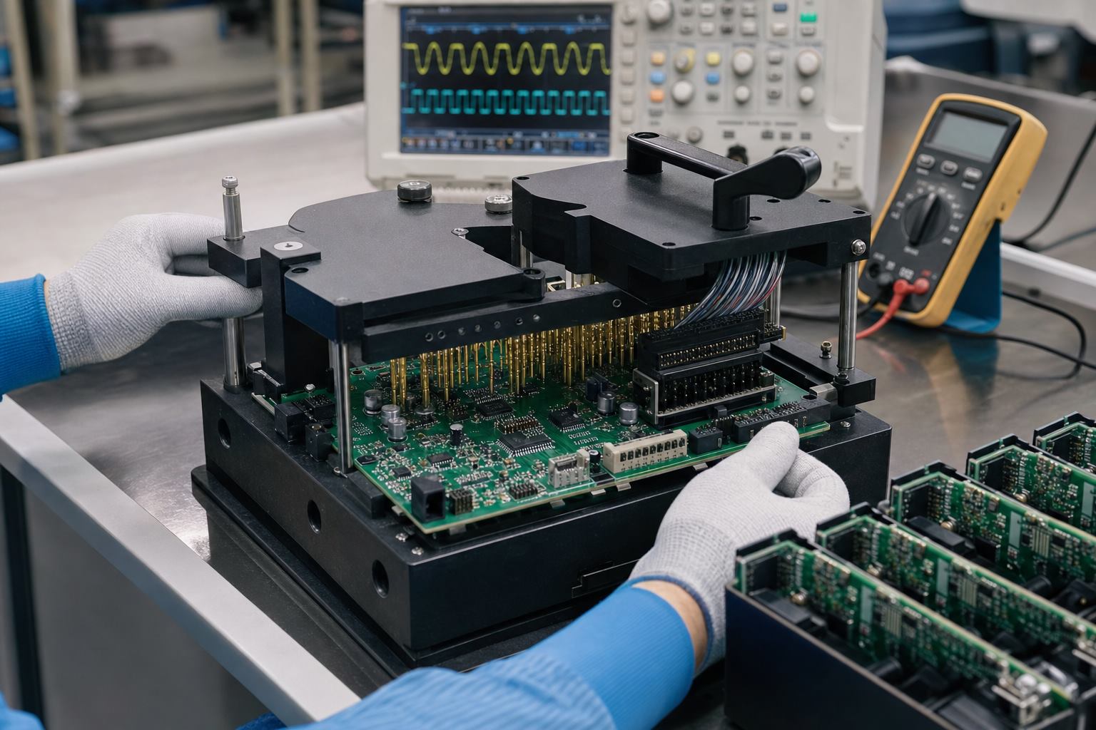
- Fixture mechanics: confirm PCB support, probe force, connector alignment, operator safety, wear points, and easy maintenance.
- Electrical protection: prevent reverse connection, overcurrent, unsafe discharge, and damage from an already-faulty unit.
- Reference strategy: maintain known-good and known-fault samples or simulation methods to check detection behavior.
- Software control: lock script, firmware, drivers, limits, and instrument configuration to released versions.
- Repeatability: run repeated measurements across operators, fixtures, and time; investigate results near limits.
- Traceability: store unit ID, date, station, fixture, software version, measured values, result, and failure code.
Pass/fail limits should come from product requirements and validated process behavior, not from copying one golden unit’s exact measurements. A limit that is too wide permits escapes; a limit that is too narrow creates false failures and unnecessary rework.
What Should PVT and the Pilot Build Measure?
PVT should measure whether the released design, materials, line, tooling, work instructions, inspection plan, and test system produce consistent results under normal manufacturing conditions. It is a production experiment, not an engineering showcase.
Use production-intent suppliers, parts, PCB panels, assembly equipment, operators, firmware-loading method, fixtures, labels, packaging, and data systems. Track first-pass yield by process step, defect and failure-code Pareto, cycle time, repair rate, no-fault-found rate, fixture downtime, component substitutions, deviations, and traceability completeness.
Review failures by mechanism rather than only by count. A small number of repeated contact failures may indicate a weak fixture. Random resets may point to electrical margin, programming, or firmware state. Solder defects concentrated on one package may require footprint, stencil, thermal-profile, handling, or component-finish review. Corrective action should update the controlled design or process documents and trigger appropriate regression testing.
How Do You Control Failures, Changes, and Test Data?
Failures and changes should be managed through a closed loop that preserves evidence, controls revisions, and proves the correction. Without this discipline, teams repeatedly fix symptoms, mix configurations, or release changes that invalidate earlier test results.
- Contain affected samples, lots, files, and test stations.
- Describe the failure condition and reproduce it where possible.
- Separate symptom, physical mechanism, and root cause.
- Implement corrective action through controlled engineering or process change.
- Verify the fix on affected tests and run regression tests for nearby risks.
- Update drawings, BOM, Gerbers, firmware, work instructions, fixture files, limits, and revision history together.
- Monitor later builds to confirm the correction remains effective.
Useful test data should support decisions. Store measured values when they help detect drift, not only pass/fail. Trend parameters such as current, calibration values, RF power, temperature rise, or test duration when they are linked to product or process risk. Protect access and retention according to customer, product, and regulatory needs.
What Files Should Be Released to the Manufacturing Partner?
The manufacturing package should define exactly what to build, how to inspect and test it, and how to report deviations. Send controlled revisions and one release index so the factory does not have to infer which files belong together.
- Gerber or approved fabrication data, drill data, stack-up, material, finish, copper, impedance, panel, and special notes.
- BOM with manufacturer part numbers, approved alternates, do-not-substitute rules, and lifecycle concerns.
- Pick-and-place data, assembly drawings, polarity and orientation notes, stencil requirements, and mechanical drawings.
- Programming files, secure provisioning method, firmware revision, checksums, and recovery instructions.
- Inspection criteria, X-ray requirements, workmanship class or customer criteria where contractually defined.
- Functional test specification, setup, sequence, limits, fixture interface, diagnostic codes, and example results.
- Label, serial number, traceability, packaging, moisture, ESD, and shipping requirements.
- Approved deviation process, engineering contacts, and change-notification requirements.
For a manufacturing review or quotation, provide the maturity level and unresolved risks as well as the files. Best Technology can review PCB fabrication, component sourcing, PCBA assembly, inspection, and test needs as one handoff. Available equipment and test information can be reviewed on the quality and test equipment page.
Electronic Product Development Testing FAQs
What is the difference between verification and validation?
Verification checks whether the design meets specified requirements; validation checks whether the resulting product meets the intended user need and use environment. A voltage measurement can verify an electrical requirement, while a field-representative use test can help validate that the complete product solves the intended problem.
Why can a prototype work while production units fail?
A prototype may receive hand assembly, expert debugging, selected parts, and flexible rework. Production introduces normal variation in components, soldering, handling, operators, fixtures, and environment. Marginal footprints, missing test access, weak electrical margin, or uncontrolled substitutions often appear only when repeatability is required.
What are practical EVT exit criteria?
EVT can exit when core functions and interfaces meet agreed targets, high-risk electrical and thermal behavior has been measured, critical defects have corrective actions, remaining risks are documented, and the design is mature enough for production-intent DVT samples. The criteria should be agreed before the build.
How many samples are needed for DVT?
There is no universal DVT sample count. It depends on product risk, test destructiveness, configuration variants, reliability goals, compliance plans, and confidence required. Create a sample allocation matrix with the responsible engineer and relevant test laboratories rather than copying a generic number.
When should EMC testing begin?
EMC risk review should begin during architecture and PCB layout. Bench pre-compliance checks during EVT can reveal grounding, filtering, cable, enclosure, and routing problems while changes remain manageable. Formal testing should use a stable production-intent configuration appropriate to the target market and product category.
What is a golden sample?
A golden sample is a controlled reference unit with known configuration and measured behavior. It can help check fixtures and compare failures, but it should not be the sole source of pass/fail limits. Requirements, tolerances, measurement uncertainty, and validated production data should determine limits.
Do AOI and X-ray replace functional testing?
No. AOI checks visible assembly conditions, and X-ray helps inspect hidden joints and structures. They can find manufacturing defects but cannot prove that firmware, interfaces, sensors, power behavior, or the full product function meets requirements. Inspection and functional testing cover different fault classes.
What is test coverage in production?
Test coverage describes how well the test strategy can detect defined faults or verify requirements. It is not simply the number of test steps. Teams should map likely failure modes and critical functions to inspection, electrical test, programming checks, functional tests, and sampling-based reliability activities.
Should firmware be tested separately from hardware?
Firmware needs unit and integration testing, but hardware-in-the-loop and complete-product tests are also necessary. Timing, power transitions, sensors, communication, memory, recovery, provisioning, and fault behavior emerge from the interaction between firmware, electronics, and the production configuration.
How often should production test limits be reviewed?
Review limits after design or process changes, fixture maintenance, instrument changes, abnormal yield shifts, field failures, or evidence of measurement drift. Routine trend review can identify problems before pass/fail rates change. Any update should be authorized, versioned, validated, and linked to the affected stations.
What information is needed for an electronic product testing quote?
Provide product function, target market, design maturity, schematic, PCB files, BOM, firmware needs, enclosure data, expected volume, known risks, required tests, acceptance limits, and desired deliverables. If requirements are incomplete, identify them clearly so the supplier can scope engineering work rather than assuming coverage.
Can one supplier handle design, PCB, assembly, and testing?
Yes, an integrated supplier can coordinate design feedback, PCB fabrication, component sourcing, assembly, prototypes, fixtures, and production testing. Buyers should still confirm responsibilities, file ownership, change control, test evidence, capability, and which compliance activities require an external accredited laboratory.
Build the Test Strategy Before You Build the Fixture
The strongest electronic product development testing plan begins with requirements and risk, then adds the right reviews, prototypes, validation stages, fixtures, data, and release evidence. Planning DFM and DFT early reduces avoidable redesign, while disciplined EVT, DVT, and PVT gates keep engineering success separate from production readiness.
If you are sourcing electronic product design support, PCB prototyping, PCB assembly, OEM/ODM development, sample validation, or production testing, contact the Best Technology engineering team at sales@bestpcbs.com for a technical review and quotation.







