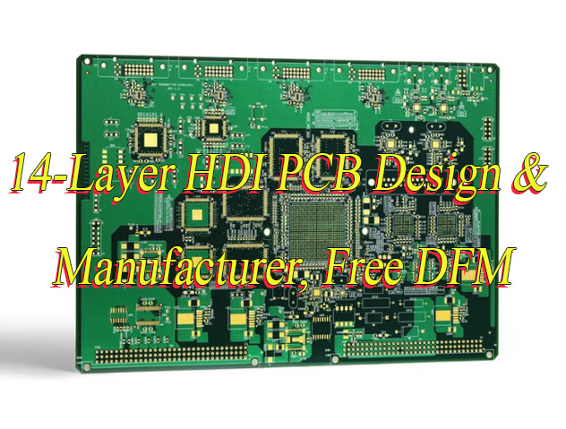
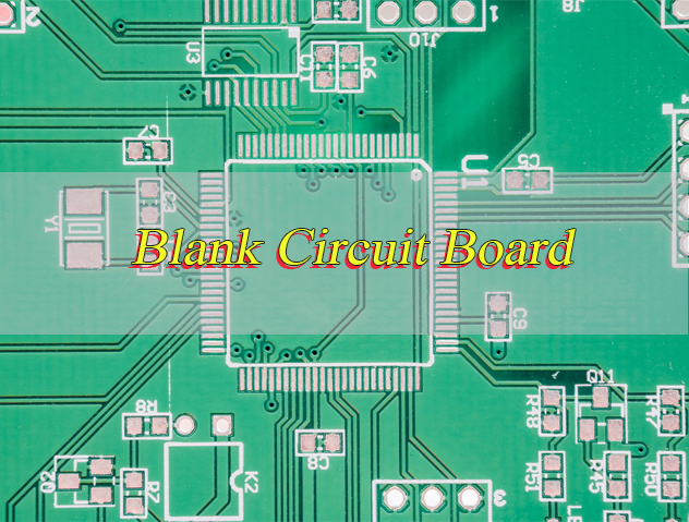
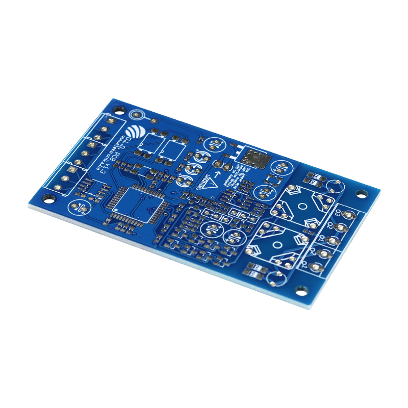
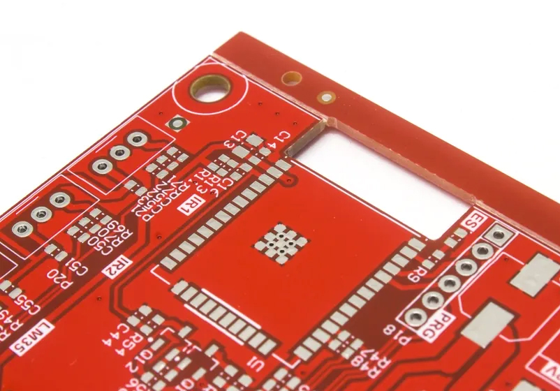
A blank circuit board (also called bare or empty PCB) is an unpopulated electronic assembly foundation requiring precision engineering for reliability. High-quality blank PCBs need strict process controls and professional design, where EBest, a top China blank PCB manufacturer, offers full solutions from design to mass production to meet your needs.
Why Choose EBest for China Blank Circuit Board Manufacturers?
EBest, a leading China-based blank circuit board manufacturer with over 20 years of experience, specializes in high-reliability blank PCBs for mission-critical sectors, supported by IATF 16949, ISO 13485, AS9100D, RoHS, REACH and UL. Our advanced facilities produce diverse solutions: rigid, flexible, metal-core, 1-30 layers for modern electronic applications.
- Full-Cycle Turnkey Capabilities: Save you 30% of project time and 25% of coordination costs by integrating design optimization, rapid prototyping, manufacturing, and testing in-house—eliminating the need to coordinate 3+ suppliers, while ensuring 99.9% quality consistency across all production stages.
- Stringent Quality Assurance: Reduce your product failure rate to 0.05% or lower with 100% electrical testing, AOI inspection, and impedance verification; our strict process controls ensure blank PCBs meet IPC 6013 Class 3 standards, extending your end-product service life by 20%.
- Fast, Reliable Delivery: Cut your product development cycle by 40% with 3-5 day standard prototype delivery and 7-10 day mass production turnaround; 24-hour express service for urgent orders ensures you meet market launch deadlines, boosting your time-to-market advantage by 35%.
- Tailored Custom Solutions: Match your unique application needs with customized substrates, surface finishes, and specs, reducing material waste by 15% and ensuring 100% compatibility with your end-product, avoiding costly redesigns due to mismatched standard boards.
- Competitive, Transparent Pricing: Leverage our 260,000 square feet monthly production capacity to save 18-30% on unit costs vs. small manufacturers; volume discounts (up to 25% for orders over 10,000 pieces) further reduce your mass production expenses without compromising quality.
- Dedicated Technical Support: Our DFM analysis reduces prototype iterations by 40%, cutting prototype costs by 30% and accelerating your time-to-market by an average of 2-3 weeks—ensuring your design is manufacturable and cost-effective from the start.
Blank Circuit Board Design: Challenges & EBest’s Solutions
Blank circuit board design transforms electronic concepts into manufacturable substrates balancing electrical performance, mechanical integrity, and production feasibility. Poor blank PCB design causes signal interference, manufacturing failures, and costly delays. EBest’s engineering team resolves these challenges through specialized expertise.
What Are Common Design Challenges?
- Signal Integrity Issues: High-speed signals suffer reflection, crosstalk, and EMI without proper impedance control
- Thermal Management: Inadequate heat dissipation leads to component failure in high-power applications
- Space Constraints: Compact layouts create routing conflicts and assembly difficulties
- Manufacturing Compatibility: Non-standard features cause production errors and low yields
- Material Selection: Choosing inappropriate substrates for operating environments
How EBest Solves Design Challenges?
- Advanced Simulation: Signal integrity and thermal analysis before production
- DFM Expertise: Optimize layouts for manufacturing, reducing prototypes by 40%
- Layer Stack Expertise: Proper plane separation ensures signal quality and noise reduction
- Precision Routing: Controlled impedance, differential pairs, and minimal 90° angles
- Industry-Specific Design: Medical (ISO 13485), aerospace (AS9100D), and industrial standards
Medical Case Study: Designed a 6-layer blank PCB for a portable ultrasound device with 0.2mm trace/space, controlled impedance (±5%), and ENIG finish. The design passed all IPC 6013 Class 3 requirements and supported 500+ hour continuous operation.
For superior blank circuit board design that balances performance and manufacturability, partner with EBest. Our engineering team delivers optimized layouts for any application.
Blank Circuit Board Prototype: Challenges & EBest’s Solutions
Blank circuit board prototype development validates designs before mass production identifying issues early. Common challenges include long lead times, poor quality, and inconsistent performance. EBest provides rapid, reliable blank PCB prototype services with strict quality controls.
What Prototype Challenges Do Users Face?
- Long Lead Times: Traditional manufacturing delays product development
- Quality Inconsistencies: Prototypes failing testing or not matching specifications
- High Costs: Small-quote premiums and repeated iterations increase expenses
- Limited Materials: Restricted access to specialized substrates
- Documentation Errors: Incorrect files cause manufacturing failures
How EBest Delivers Superior Prototypes?
Our blank circuit board prototype services solve these issues:
- Rapid Turnaround: 24-hour express, 3-5 day standard delivery
- Precision Manufacturing: Advanced laser plotting and plating technologies
- Full Material Selection: FR-4, high-TG, aluminum, Rogers, and flexible substrates
- Strict Quality Control: 100% electrical test, AOI, and microsection analysis
- DFM Feedback: Free design review to optimize for mass production
Aerospace Case Study: Produced 10 prototype 8-layer blank printed circuit boards for a satellite communication module using Rogers 4350B substrate. The prototypes passed thermal cycling (55°C to 125°C) and vibration testing (20G), validating performance for space applications.
Accelerate your development with reliable blank circuit board prototype solutions from EBest. We deliver high-quality samples quickly to validate your design efficiently.
Blank Circuit Board Assembly: Challenges & EBest’s Solutions
Blank circuit board assembly transforms bare substrates into functional electronic assemblies. Challenges include component placement accuracy, solder quality, and process controls. EBest’s blank PCB assembly services ensure flawless execution from prototypes to mass production.
What Assembly Challenges Exist?
- Solder Defects: Cold joints, bridges, and tombstoning cause failures
- Component Misalignment: High-density placement requires precision
- Thermal Damage: Sensitive components damaged during soldering
- Quality Variability: Inconsistent results between batches
- Testing Complexity: Comprehensive verification for complex assemblies
How EBest Ensures Assembly Excellence?
Our blank circuit board assembly services overcome these challenges:
- Advanced Equipment: Automated SMT lines with 01005 component capability
- Process Controls: Optimized solder paste printing and reflow profiles
- Skilled Technicians: IPC-A-610 certified operators
- Quality Inspection: AOI, X-ray, and functional testing for all assemblies
- Material Management: Complete BOM support and component sourcing
Industrial Case Study: Assembled blank PCB for a factory automation PLC with 1,200+ components including 0402 passives and QFP devices (0.5mm pitch). Achieved 99.8% first-pass yield and 30,000+ hour MTBF for continuous operation.
For reliable blank circuit board assembly with exceptional quality, choose EBest. Our comprehensive services ensure your assemblies perform flawlessly.
What Is a Blank Printed Circuit Board?
A blank circuit board, also known as a bare circuit board or empty circuit board, is an unpopulated electronic substrate that provides a mechanical foundation and pre-designed electrical pathways (traces, pads, and vias) for mounting electronic components. Unlike assembled PCBs, it contains no soldered components serving as the base structure that is later populated with resistors, capacitors, chips, and other parts to form a functional electronic circuit. Blank circuit boards are manufactured with precise materials and processes to ensure electrical conductivity, mechanical stability, and compatibility with various component types making them essential for all electronic devices across medical, aerospace, and industrial sectors.
What is a Blank Circuit Board Called?
A blank circuit board has several industry terms:
- Bare circuit board / bare PCB: Most common description
- Empty circuit board: Emphasizes unpopulated state
- Blank PCB: Standard industry abbreviation
- Blank printed circuit board: Full technical designation
- Circuit board blanks: Plural reference to unprocessed substrates
These terms all describe the same unpopulated substrate before component assembly.
What Are Types of Blank PCB Circuit Board?
The layer count of a blank circuit board refers to the number of conductive copper layers embedded in the substrate directly impacting its complexity and functionality.
- Single-sided: Features a single conductive layer making it the simplest and most cost-effective option. It is ideal for low-density designs and simple electronics where component placement is straightforward such as basic sensors or simple control circuits.
- Double-sided: Equipped with two conductive layers allowing for more component placement and more complex circuit routing compared to single-sided boards. This type is widely used in most consumer electronics including remote controls, small appliances, and basic communication devices.
- Multilayer (3-30 layers): Consists of alternating conductive and insulating layers enabling high-density component placement and efficient signal routing. These boards are designed for high-speed, complex devices like smartphones, medical equipment, aerospace systems, and industrial control units that require advanced functionality in a compact space.
What is HS Code of Blank Circuit Board?
The primary HS code for blank circuit board (unpopulated) is 85340090 in China. This classification covers:
- Bare printed circuit boards without components
- Blank PCB substrates of all materials
- Single, double, and multilayer circuit board blanks
Additional documentation may include:
- Substrate material specification
- Layer count and thickness
- Copper weight
- Surface finish type
Proper classification ensures smooth customs clearance for international shipments.
What Materials Are Used for Blank Circuit Boards?
| Material Category | Specific Types | Composition/Key Features | Properties |
| FR-4 Glass Reinforced Epoxy | Standard FR-4, High-TG FR-4 | Epoxy resin with glass fiber reinforcement; High-TG variant for enhanced thermal stability | Good mechanical strength, electrical insulation, flame retardant (UL94 V-0); Standard TG: 130°C-150°C; High-TG: 170°C+ |
| High-Frequency Materials | Rogers, Taconic, PTFE (Teflon) | Specialized substrates designed for high-frequency applications | Low dielectric loss; PTFE offers excellent high-frequency performance but higher cost |
| Flexible Substrates | Polyimide (PI), Polyester (PET) | Bendable, lightweight substrates for flexible applications | Polyimide: Temperature resistance (200°C to 260°C), flexibility; PET: Lower cost, limited temperature range |
| Metal Core Substrates | Aluminum, Copper | Metal core (aluminum or copper) for heat dissipation | Excellent thermal conductivity; Copper has superior thermal performance but higher cost than aluminum |
| Specialty Materials | Ceramic, Composite (CEM-1/CEM-3) | Specialized substrates for unique application needs | Ceramic: High-temperature resistance, excellent insulation; CEM-1/CEM-3: Cost-effective alternative to FR-4 |
Material selection for blank circuit boards depends on operating temperature, electrical requirements, and environmental conditions. The table above summarizes the key materials, their features, and properties to help you make the right choice for your application.
How to Use Blank Circuit Board?
Using a blank circuit board involves several key, sequential steps that ensure proper assembly, functionality, and reliability critical for medical, aerospace, and industrial applications. Each step focuses on precision to avoid assembly errors and component failure leveraging best practices for blank PCB utilization:
1. Preparation & Verification
- Confirm the blank circuit board dimensions, layer count, copper weight, and surface finish match your design specifications (e.g., ENIG finish for medical devices, high-TG substrate for industrial use).
- Inspect the bare circuit board for defects: scratches on conductive traces, delamination of layers, irregularities in solder mask, or contamination that could impact soldering.
- Clean the empty circuit board surface with isopropyl alcohol or specialized cleaning agents to remove dust, oil, or residue ensuring strong solder adhesion and electrical conductivity.
2. Component Preparation
- Gather all electronic components (resistors, capacitors, chips, connectors) and verify their specifications (value, size, voltage rating) match the BOM (Bill of Materials) for your blank PCB.
- Prepare solder paste (matching alloy type for your application), a precision stencil aligned to the blank circuit board’s pad layout, and assembly tools (soldering iron, pick-and-place equipment for high-volume projects).
- Develop or load a component placement program (for automated assembly) based on your design files (Gerber, BOM) ensuring accurate alignment with the blank printed circuit board’s pads and vias.
3. Assembly Process
- Apply solder paste to the blank circuit board using a precision stencil ensuring uniform paste thickness (critical for small components like 0402 passives or QFP chips).
- Place components on the blank PCB manually for small prototypes or via automated SMT lines for mass production aligning pins perfectly with pads to avoid short circuits.
- Reflow solder in a controlled oven following a temperature profile tailored to the component type and solder alloy ensuring proper melting and adhesion without damaging the circuit board blank or components.
- Clean the assembled blank circuit board to remove flux residues (especially critical for medical or aerospace applications) using a solvent compatible with the board’s surface finish.
4. Testing & Validation
- Perform a visual inspection (manual or AOI) to check for solder defects (cold joints, bridges, tombstoning) and component misalignment on the blank PCB assembly.
- Conduct electrical testing (flying probe or fixture test) to verify continuity, isolation, and impedance control ensuring the blank circuit board’s pathways function as designed.
- Complete functional testing to confirm the assembled board operates as intended matching the performance requirements of your application (e.g., signal integrity for aerospace communication).
- Optional environmental stress testing (thermal cycling, vibration, humidity) for high-reliability sectors ensuring the bare circuit board assembly withstands harsh operating conditions.
5. Integration
- Install the tested blank circuit board assembly into the final product housing ensuring secure mounting to prevent damage from vibration (critical for industrial equipment).
- Connect the assembly to other system components (power supplies, sensors, displays) using appropriate connectors ensuring proper electrical connections and signal integrity.
- Complete system-level testing to verify the blank printed circuit board works seamlessly with the entire system resolving any integration issues before final deployment.

How to Make Circuit Board Blanks?
Circuit board blanks manufacturing involves precise, standardized multi-step processes that ensure consistency, electrical performance, and mechanical durability essential for high-reliability blank circuit board applications. Below are the key steps focusing on critical details that impact the quality of bare circuit boards:
1. Material Preparation
- Select the appropriate substrate material (FR-4, high-TG, aluminum, Rogers, or polyimide) based on the blank PCB’s intended use (e.g., Rogers for high-frequency aerospace applications, polyimide for flexible medical implants).
- Laminate copper foil (typically 1oz-4oz) to the dielectric substrate under controlled high heat (170°C-200°C) and pressure ensuring strong adhesion between layers for multi-layer circuit board blanks.
- Cut the laminated core material to the required panel size and prepare multilayer stacks with prepreg (insulating material) between layers to ensure electrical isolation and structural integrity.
2. Imaging Process
- Apply a photosensitive photoresist (liquid or dry film) to both sides of the copper-clad substrate ensuring uniform coverage to protect the copper during etching.
- Expose the photoresist-coated blank circuit board to UV light through a precision artwork film (containing the circuit pattern) hardening the photoresist in areas that will remain as conductive traces.
- Develop the board to remove the unexposed (unhardened) photoresist revealing the copper areas that will be etched away leaving the desired circuit pattern on the blank PCB.
3. Etching Process
- Etch the exposed copper using a chemical solution (typically ferric chloride or cupric chloride) removing unwanted copper to leave only the conductive traces, pads, and vias of the blank circuit board.
- Strip the remaining hardened photoresist using a chemical stripper revealing the clean copper circuit pattern on the bare circuit board.
- Clean and inspect the panels for etching defects (over-etching, under-etching, trace damage) using AOI or manual inspection ensuring the circuit pattern matches design specifications.
4. Drilling & Plating
- Drill precision holes (through-hole or micro-vias for HDI boards) using CNC drilling equipment ensuring accurate hole size and location for component pins and interlayer connections in multi-layer blank PCBs.
- Desmear the hole walls to remove resin residue from drilling then clean the holes to ensure proper copper adhesion for plating.
- Apply electroless copper plating (thin, uniform copper layer) to the hole walls and board surface followed by electrolytic copper plating to achieve the desired copper thickness (1oz-4oz) for the blank circuit board.
- Perform pattern plating (if needed) to thicken copper on critical traces (e.g., power traces) for enhanced current-carrying capacity ensuring the circuit board blanks meet electrical requirements.
5. Final Processing
- Apply a solder mask (typically green but available in other colors) to the blank circuit board covering all areas except pads and vias to protect traces from oxidation, short circuits, and physical damage.
- Add legend/identification printing (silk screen) to the solder mask marking component designators, logos, and polarity indicators for easy assembly and troubleshooting.
- Apply the desired surface finish (HASL, lead-free HASL, ENIG, OSP, or immersion silver) to the pads ensuring strong solderability and corrosion resistance for the blank PCB.
- Route or punch the panels to the final blank circuit board dimensions removing excess material and ensuring clean, precise edges.
- Conduct final electrical testing (continuity, isolation, impedance) and visual inspection rejecting any bare circuit boards with defects to ensure only high-quality products are delivered.
Where to Buy Blank Circuit Boards?
For high-quality blank circuit boards, partner with specialized manufacturers like EBest. Key considerations when selecting a supplier:
Critical Selection Criteria
- Technical Capabilities: Layer count, minimum trace/space, hole size
- Quality Systems: Certifications (ISO 9001, IATF 16949, ISO 13485)
- Material Selection: Range of substrates and surface finishes
- Lead Times: Prototypes and mass production capabilities
- Quality Control: Testing procedures and defect rates
- Technical Support: DFM analysis and engineering assistance
EBest’s Advantages
- One-Stop Solution: Design, prototype, and full production
- Quick Quotes: 24-hour response for most inquiries
- Flexible Order Quantities: From 1 to 100,000+ pieces
- Global Shipping: Reliable worldwide delivery
- Competitive Pricing: Volume discounts and cost-effective manufacturing
How Much Does Blank Circuit Boards Cost?
Blank circuit board pricing varies based on multiple factors:
- Board Size: Larger dimensions increase material usage
- Layer Count: 1-layer ($2-$5) to 20-layer ($50-$200+)
- Complexity: Trace/space, hole size, aspect ratio
- Quantity: Prototypes ($5-$50/unit) vs. mass production ($0.50-$20/unit)
- Material: Standard FR-4 vs. high-frequency or flexible substrates
- Surface Finish: HASL (lowest), ENIG, immersion silver, gold plating
- Special Requirements: Impedance control, heavy copper, testing
Below is a price chart for blank circuit boards:
| Type | Prototype (1-10 pcs) | Mass Production (1,000+ pcs) |
| 1-layer FR-4 | $2-$8 | $0.50-$3 |
| 2-layer FR-4 | $5-$15 | $1-$5 |
| 4-layer FR-4 | $15-$40 | $3-$10 |
| 6-layer FR-4 | $30-$70 | $5-$15 |
| 8-layer High-TG | $50-$120 | $8-$20 |
| Flexible (Polyimide) | $20-$80 | $5-$25 |
| Metal Core (Aluminum) | $30-$100 | $10-$30 |
FAQs About Blank Printed Circuit Board
Q1: What’s the minimum order quantity for blank PCB?
A1: EBest accepts orders from 1 piece (prototypes) to mass production. No minimum order restrictions for standard blank circuit board specifications.
Q2: How long does blank circuit board production take?
A2: Standard prototypes: 3-5 days. Mass production: 7-10 days. Express service available (24-48 hours) for urgent requirements.
Q3: What surface finishes are available for blank PCB?
A3: Common options: HASL, lead-free HASL, ENIG (Electroless Nickel Immersion Gold), immersion silver, immersion tin, and OSP (Organic Solderability Preservative).
Q4: Can blank circuit boards withstand high temperatures?
A4: Standard FR-4 handles up to 130°C continuously. High-TG materials work up to 170°C+. Metal core and ceramic substrates handle even higher temperatures for specialized applications.
Q5: What testing is performed on blank circuit boards?
A5: Standard tests include: flying probe or fixture electrical test, AOI (Automated Optical Inspection), solder mask adhesion, and dimension verification. Special testing available upon request.
Q6: Can you manufacture custom-sized blank circuit boards?
A6: Yes, EBest produces fully customized blank circuit board dimensions, shapes, and specifications according to your design files.
Ready to Order Your Blank Circuit Boards?
EBest delivers high-quality blank circuit board solutions for medical, aerospace, industrial, and commercial applications. As a leading China blank printed circuit board manufacturer, we provide comprehensive services from design through mass production.
Our blank PCB products meet the strictest quality standards with fast delivery and competitive pricing. Whether you need prototypes or large-scale production, we offer tailored solutions to meet your exact requirements.
Contact us today to discuss your blank circuit board needs. Send your specifications and requirements to sales@bestpcbs.com for a free quote and DFM analysis. Partner with EBest for reliable circuit board blanks that power your success.