





What is a dxf file? It is a CAD exchange file that carries drawing geometry between design and manufacturing software. For PCB work, DXF is most useful for board outlines, slots, cutouts, mounting features, and enclosure references. It does not replace Gerber, drill, or other electrical fabrication data.
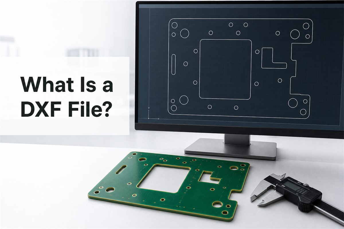
The file is only as reliable as the export. Units, scale, origin, layers, and closed contours must survive the move from one system to another. A DXF that looks correct on screen can still import at the wrong size or contain gaps that break a routing path.
What Is a DXF File?
DXF stands for Drawing Exchange Format, also called Drawing Interchange Format. It was designed to make CAD drawings easier to share between programs that use different native file formats.
A DXF can carry 2D or 3D entities, but manufacturing handoffs often use simple 2D vector geometry:
- Lines and polylines for straight edges
- Arcs and circles for radii and holes
- Closed contours for outer profiles and internal cutouts
- Layers for geometry, dimensions, notes, and references
- Coordinates, origins, and drawing units
DXF is widely supported, but it is not a full-fidelity copy of every CAD database. Design history, constraints, materials, and application-specific objects may be lost during export.
What Is a DXF File Format?
A DXF file stores drawing information in sections. These sections describe settings, layers, blocks, geometry, and other objects. Many DXF files use readable ASCII text; a binary version also exists.
For PCB mechanical data, simple entities are usually safer than complex ones. A clean file should have:
- One clearly identified board outline
- Closed contours without tiny gaps
- No duplicate or overlapping lines
- Separate layers for production geometry and notes
- A DXF version supported by the receiving software
Splines, hatch patterns, custom fonts, and complex blocks may display differently after import. Convert them only when needed, then measure the result against the approved drawing.
What Is a DXF File Used For?
DXF is used when editable geometry needs to move from design into another engineering or manufacturing system. Common uses include:
- Laser cutting and sheet-metal profiles
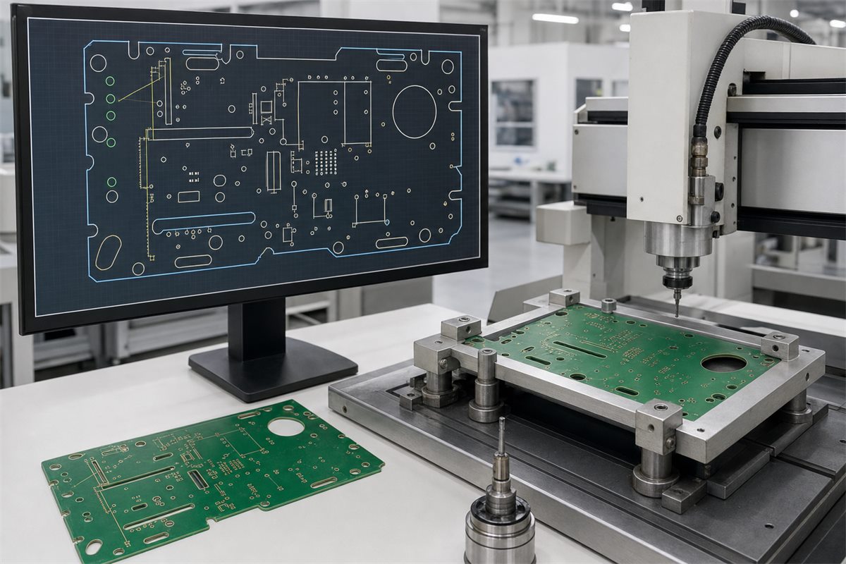
- CNC routing, engraving, and machining
- Architectural and product-design drawings
- Inspection programming and fixture design
- PCB outlines, cutouts, slots, and mounting locations
In PCB projects, DXF often bridges mechanical CAD and ECAD. An enclosure designer can define the available shape and mounting points, while the PCB designer uses that geometry to build the board inside the mechanical limits.
What Is a DXF File and How Do I Open It?
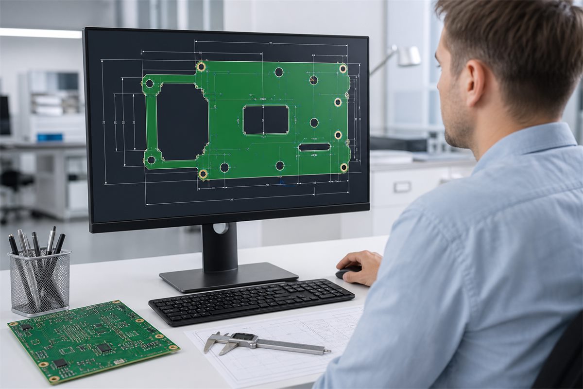
You can open a DXF with CAD, ECAD, CAM, or dedicated viewer software. Choose the tool according to the task:
- Viewer: quick visual checks and basic measurement
- CAD editor: repair, layer control, conversion, and export
- PCB layout tool: import as a board outline or mechanical layer
- CAM system: manufacturing review and tool-path preparation
After opening the file, check the units and measure one known feature. Then confirm orientation, origin, layer mapping, and whether every required contour is closed. Do not treat a successful import message as proof that the geometry is correct.
What Is a DXF File vs DWG?
DXF is mainly an exchange format, while DWG is a native CAD drawing format that often retains richer design data. The better choice depends on software compatibility and the information the receiver needs.
| Comparison | DXF | DWG |
| Primary role | Cross-platform drawing exchange | Native CAD drawing storage |
| Compatibility | Broad import and export support | Best fidelity in compatible native tools |
| Readable as text | ASCII DXF can be inspected | Normally binary |
| Data richness | Strong for transferable geometry | Often retains more native detail |
| PCB use | Outlines, cutouts, slots, and references | Useful when both teams support the same workflow |
Do not choose by extension alone. Import the actual file and verify that the approved geometry, scale, and dimensions are preserved.
How Does DXF Compare With STEP, PDF and Gerber?
Each format has a different job:
- DXF: editable 2D geometry for outlines, cutouts, and mechanical references
- STEP: 3D product, component-height, enclosure-fit, and interference review
- PDF: human-readable dimensions, tolerances, notes, and approvals
- Gerber: PCB copper, solder mask, and legend image layers
- Drill data: hole coordinates, tool sizes, and plated or non-plated intent
A PCB production release still needs the correct PCB Gerber file and drill data. DXF supports the mechanical definition; it does not describe the complete electrical board.
Design-source files serve another purpose. This overview of PCB schematic drawing file types explains the difference between logical design data and manufacturing outputs.
How Are DXF Files Used in PCB Design and Manufacturing?
A practical PCB workflow is short and controlled:
- The mechanical engineer exports the board perimeter, mounting points, and enclosure constraints.
- The PCB designer imports the DXF and maps the approved contour to the board-outline layer.
- The designer checks scale, origin, orientation, cutouts, and copper-to-edge clearance.
- The final fabrication package is generated with Gerber or ODB++, drill data, drawings, and notes.
- The manufacturer compares the DXF reference with the official fabrication data before tooling.
Any mismatch between DXF and Gerber should be resolved before production. Neither file should silently override the other.
Special mechanical features need clear dimensions and notes. If the design includes recessed hardware, review the distinction between a countersink and counterbore on a PCB drawing instead of relying on the DXF appearance alone.
How Do You Prepare a Clean DXF File?
Prepare the file for the receiving system, not just for the software that created it. Use this checklist:
- State the units. Record millimeters or inches in the export settings and drawing notes.
- Keep one final outline. Remove construction lines, old revisions, and alternate profiles.
- Close every contour. Join endpoints and inspect small gaps at high zoom.
- Remove duplicates. Overlapping lines can create ambiguous or repeated tool paths.
- Simplify risky objects. Convert unsupported splines, blocks, or fonts only when necessary.
- Separate layers. Keep routing geometry apart from dimensions, notes, and reference lines.
- Confirm origin and orientation. Check that the drawing is not shifted or mirrored.
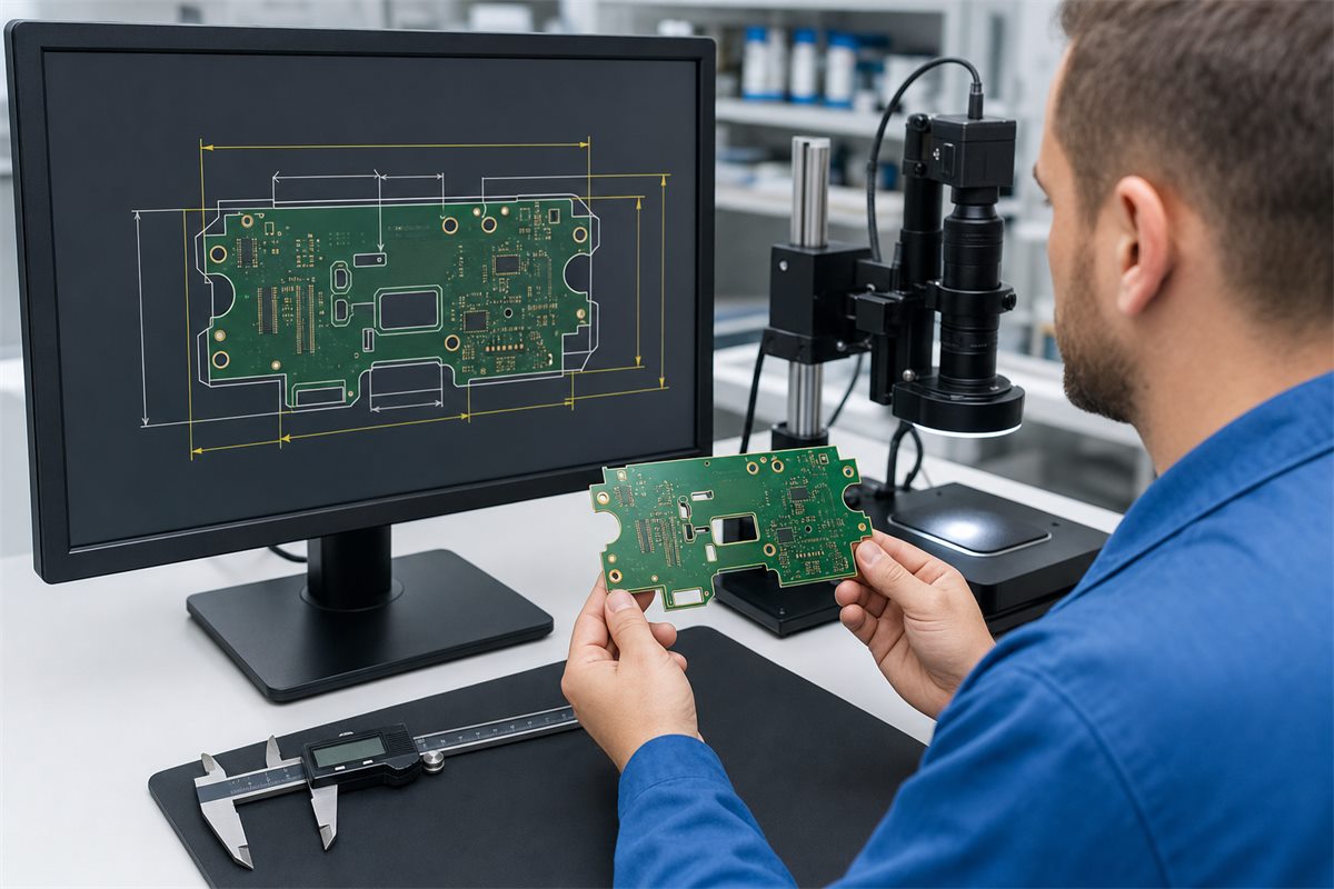
- Reopen and measure. Verify at least one critical dimension in another tool.
These checks belong in the wider PCB DFM review. A few minutes spent on geometry can prevent a routed panel or enclosure mismatch.
What Problems Cause DXF Import Errors?
Most DXF failures come from a small group of issues:
- Millimeter and inch mismatches
- Unsupported DXF versions or entities
- Open contours or zero-length segments
- Duplicate and overlapping geometry
- Missing fonts, invalid blocks, or excessive hatch data
- Mirrored geometry or an unexpected coordinate origin
If an import fails, simplify the source drawing and export a compatible version. If it opens but looks wrong, compare it with a known dimension or approved PDF. Repeated format conversion without measurement can compound small errors.
What Should You Send With a DXF File?
For PCB manufacturing, send the DXF as one part of a controlled release package. Include:
- Gerber or ODB++ fabrication data
- NC drill files
- A dimensioned fabrication drawing
- Stackup, material, copper, and finish requirements
- Revision information and a short readme
- Assembly data and a STEP model when required
State which file controls each feature. If the DXF controls the perimeter, the outline in the fabrication data must match it. If the DXF is reference-only, say so. This is a basic part of a reliable PCB design and fabrication process.
What Are Frequently Asked Questions About DXF Files?
Is a DXF file 2D or 3D?
It can store both, but PCB and cutting workflows usually use DXF for 2D vector geometry. STEP is generally better for a full 3D assembly or enclosure-fit review.
Can I view a DXF without CAD software?
Yes. A DXF viewer can display and measure many files. Production approval should still use software that confirms units, scale, and geometry.
Can a DXF contain dimensions?
Yes. Put dimensions and notes on a separate layer so they cannot be mistaken for cutting or routing geometry.
Why does a DXF import at the wrong size?
The usual cause is a unit or scale mismatch. Check the export unit, import unit, and one known dimension.
Why are curves broken after import?
The receiving software may not support the exported spline or curve type. Convert it to controlled arcs or polylines, then compare the result with the original.
Can DXF replace Gerber files?
No. DXF can describe mechanical geometry but not the complete copper, solder-mask, legend, and drill information required for PCB fabrication.
Should the PCB outline appear in both DXF and Gerber?
It may appear in both, but the geometry must match. The fabrication notes should identify which source controls the final edge.
What DXF version should I send?
Use a version confirmed by the receiving system. When in doubt, simple 2D entities in a widely supported version reduce compatibility risk.
Does DXF include manufacturing tolerances?
It can carry tolerance notes, but critical requirements should also appear in a controlled fabrication drawing.
How do I check whether a DXF outline is closed?
Use the CAD application’s join, contour, or region tools. Then inspect endpoints, duplicate lines, and small gaps after export.
Is a DXF enough for a PCB quote?
No. A quote also needs layer count, board size, materials, copper weight, surface finish, drill data, quantities, tolerances, and other fabrication requirements.
How Should You Use DXF in a PCB Manufacturing Package?
Use DXF for clear mechanical geometry, then support it with the electrical fabrication data and a dimensioned drawing. Before release, check units, scale, closed contours, origin, and agreement with the Gerber outline.
For an unusual board profile, internal cutouts, or enclosure-driven geometry, use this what is a dxf file checklist before sending the package. Best Technology can then review the DXF, Gerber outline, drill data, and fabrication notes together instead of resolving conflicts after tooling starts.







