





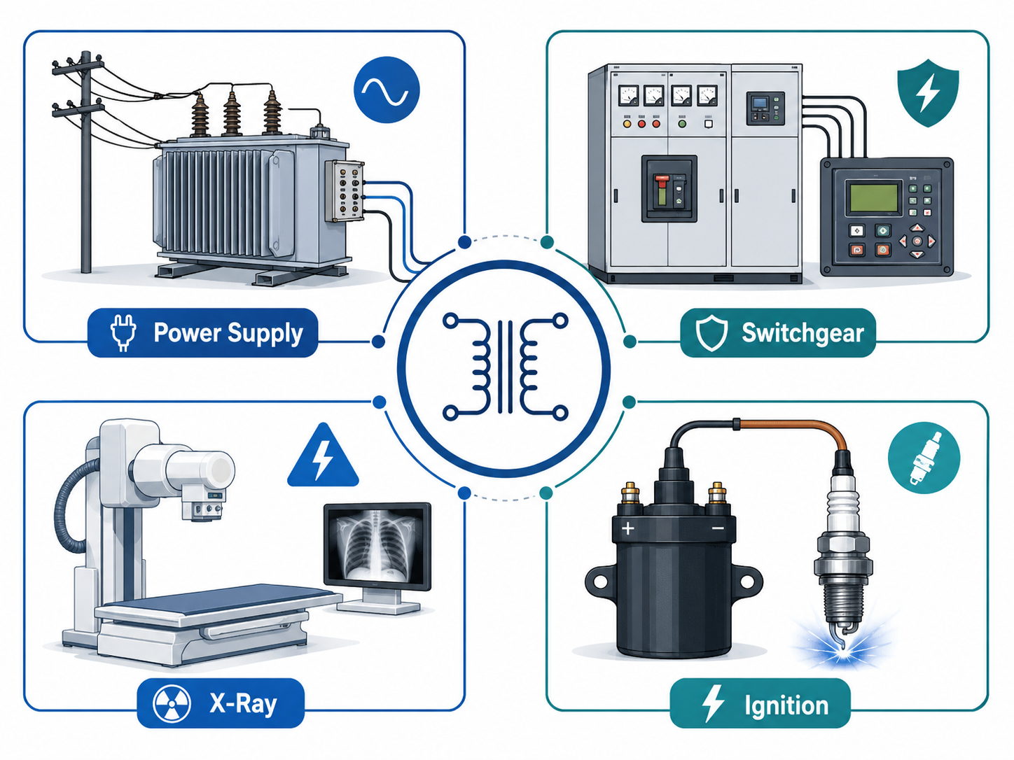
A secondary circuit is the part of an electrical system that receives converted power, measurement signals, or control information from a primary circuit. The term is common in transformers, power supplies, switchgear, X-ray equipment, automotive ignition systems, and laboratory instruments.
However, “secondary” does not automatically mean low voltage or low risk. A control transformer may provide 24 VAC, while an ignition coil or X-ray transformer can generate several thousand volts. The correct interpretation always depends on the equipment and the circuit function.
What Is a Secondary Circuit?
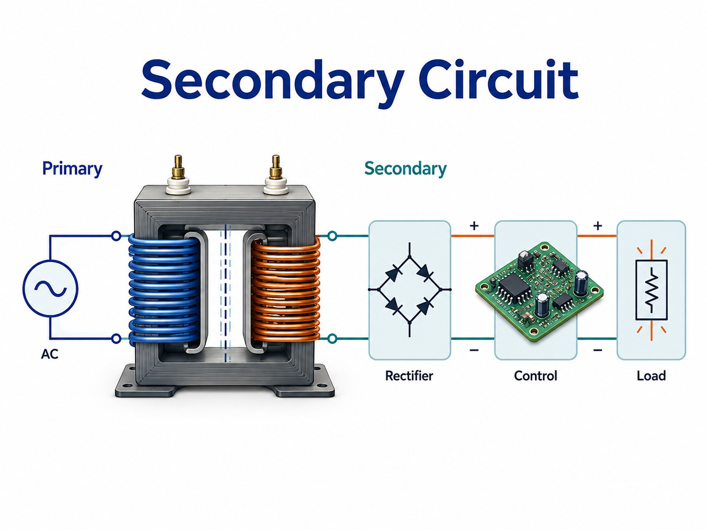
A secondary circuit is supplied or influenced by a related primary circuit. In a conventional transformer, the primary winding connects to the input source, while the secondary winding delivers electrical energy to the load.
In power distribution equipment, the term has a wider meaning. Secondary wiring may connect current transformers, voltage transformers, protection relays, meters, alarms, auxiliary contacts, and breaker trip coils.
Depending on the application, it may:
- Supply converted electrical power
- Isolate the load from the input source
- Carry measurement signals
- Operate relays or circuit breakers
- Deliver high voltage to an X-ray tube or spark plug
- Transmit status, alarm, or interlock signals
The circuit function should therefore be confirmed before selecting components, defining test methods, or interpreting a secondary circuit diagram.
How Does a Secondary Circuit Work?
In a transformer, alternating current in the primary winding creates a changing magnetic field in the core. This magnetic field induces a voltage in the secondary winding.
Where:
- Vs is the secondary voltage
- Vp is the primary voltage
- Ns is the number of secondary turns
- Np is the number of primary turns
A secondary winding with fewer turns normally reduces voltage. A winding with more turns increases voltage. The available current changes in the opposite direction, although actual output also depends on transformer rating, winding resistance, efficiency, and load conditions.
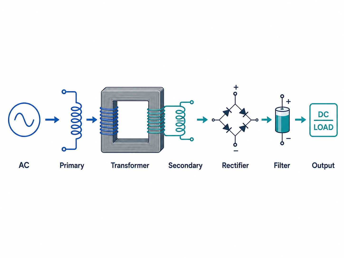
The transformer output remains AC until it passes through rectification and filtering. In measurement and protection systems, a current transformer or voltage transformer instead produces a reduced representation of the primary electrical quantity for relays and meters.
What Is the Difference Between a Primary and Secondary Circuit?
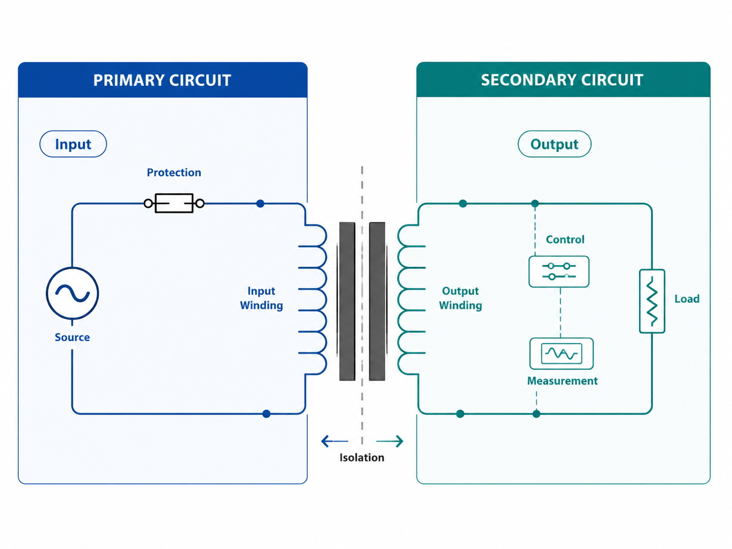
The most useful distinction is based on where each circuit receives energy and what function it performs.
| Item | Primary Circuit | Secondary Circuit |
|---|---|---|
| Position | Input or source side | Output, control, or measurement side |
| Typical connection | Mains, battery, generator, or power conductor | Load, relay, meter, controller, or output connector |
| Transformer winding | Primary winding | Secondary winding |
| Main function | Introduces energy into the system | Converts, distributes, measures, or controls energy |
| Voltage | Determined by the input source | May be lower, equal, or higher |
| Electrical isolation | Source side of the system | Possible with separate transformer windings |
| Common protection | Input fuse, breaker, surge protection | Output fuse, current limit, or secondary breaker |
| Typical PCB concern | Mains spacing, surge, and inrush current | Output current, regulation, grounding, and isolation |
| Common fault | Input overvoltage or winding damage | Open circuit, overload, polarity error, or insulation failure |
A secondary-side fault can still damage the transformer, PCB, wiring, and connected equipment. It should not be treated as a less critical part of the design.
Is a Secondary Circuit Always Low Voltage?
No. The voltage depends on the turns ratio and the equipment function.
| Application | Secondary Function | Relative Voltage |
|---|---|---|
| AC adapter | Powers low-voltage electronics | Lower |
| Industrial control transformer | Supplies relays and contactors | Lower |
| Isolation transformer | Separates source and load | Similar |
| Current transformer | Produces a measurement signal | Reduced current |
| Ignition coil | Creates spark-plug voltage | Much higher |
| X-ray generator | Supplies the X-ray tube | Much higher |
| Switch-mode power supply | Produces regulated output rails | Application-specific |
Electrical isolation is also not guaranteed. A transformer with separate windings can provide galvanic isolation, but an autotransformer shares part of the winding between input and output.
For PCB design, engineers must verify the actual working voltage, peak voltage, transient conditions, pollution degree, altitude, and required insulation category. The word “secondary” alone is not enough to calculate creepage or clearance.
What Components Are Used in a Secondary Circuit?
A transformer-based power circuit commonly includes:
- Secondary winding
- Rectifier diodes or bridge rectifier
- Filter capacitors
- Voltage regulator or DC-DC converter
- Output fuse or resettable protection device
- Current-sense resistor
- Filter inductors
- Output connector and downstream load
A switchgear or protection circuit may contain current and voltage transformers, protection relays, energy meters, auxiliary contacts, breaker coils, test switches, terminal blocks, alarms, and communication modules.
Component ratings must be coordinated. Rectifiers need sufficient forward-current and reverse-voltage margin. Capacitors must withstand the rectified peak voltage and ripple current. Connectors, terminals, and PCB traces must carry continuous and short-duration current without excessive temperature rise.
For multi-output transformers, the documentation should also state whether the windings are isolated, center-tapped, series-connected, parallel-connected, floating, or tied to ground.
How Do You Read a Secondary Circuit Diagram?
Begin by locating the circuit source. This may be a transformer secondary winding, control power supply, current transformer, voltage transformer, or auxiliary DC supply.
Then trace the path toward the load or control device:
- Identify the winding or instrument-transformer terminals.
- Confirm terminal polarity and winding ratio.
- Locate fuses, breakers, and disconnect points.
- Trace contacts, relay coils, and interlocks.
- Find the neutral, return path, reference ground, or protective earth.
- Check terminal numbers and drawing cross-references.
- Locate test links and CT shorting blocks.
- Confirm whether contacts are shown in their normal energized or de-energized state.
A circuit breaker secondary wiring diagram may include separate paths for closing, tripping, anti-pumping, spring charging, status indication, and remote control.
For PCB assembly, a schematic is not sufficient by itself. The supplier also needs the BOM, placement file, transformer pinout, connector definition, polarity marks, and functional test requirements.
How Is a Secondary Circuit Used in Transformers and Power Supplies?
In a linear power supply, the transformer secondary determines the available AC voltage and current. The output then passes through rectification and filtering before it reaches the load.
This is only a preliminary value. The actual output changes with input voltage tolerance, transformer regulation, winding resistance, diode forward voltage, filter capacitance, ripple current, and load current.
Selecting an unnecessarily high secondary voltage increases regulator heat and capacitor stress. Selecting too little voltage can cause regulator dropout at low-line input or full load.
A useful transformer specification should include:
- Input voltage and frequency
- Required secondary RMS voltage
- Continuous and peak current
- Number of output windings
- Isolation and center-tap requirements
- Maximum temperature rise
- Dielectric withstand voltage
- Mechanical size, mounting, and pin arrangement
Switch-mode power supplies use the same basic magnetic-transfer principle but operate at higher frequency. Their secondary sections may include synchronous rectifiers, Schottky diodes, output inductors, feedback isolation, and several regulated voltage rails.
What Is a Secondary Circuit in Power Systems and Switchgear?
In switchgear and substations, the primary circuit carries the main electrical power. Secondary circuits handle measurement, protection, control, and supervision.
Typical functions include:
- Current and voltage measurement
- Overcurrent, earth-fault, and differential protection
- Breaker closing and tripping
- Electrical interlocking
- Alarm transmission and remote indication
- Energy metering and control-system communication
Current transformers commonly provide standardized 1 A or 5 A secondary signals for meters and protection relays. Voltage transformers reduce system voltage to a level that can be measured safely.
Secondary wiring errors can affect the entire protection scheme. Reversed polarity, crossed phases, loose terminals, excessive loop resistance, or unintended grounding may cause incorrect measurements, false trips, or failure to trip.
The required conductor size should be based on circuit current, loop resistance, fault conditions, and the connected relay or coil. Long cable runs may require a larger conductor even when the nominal current is modest.
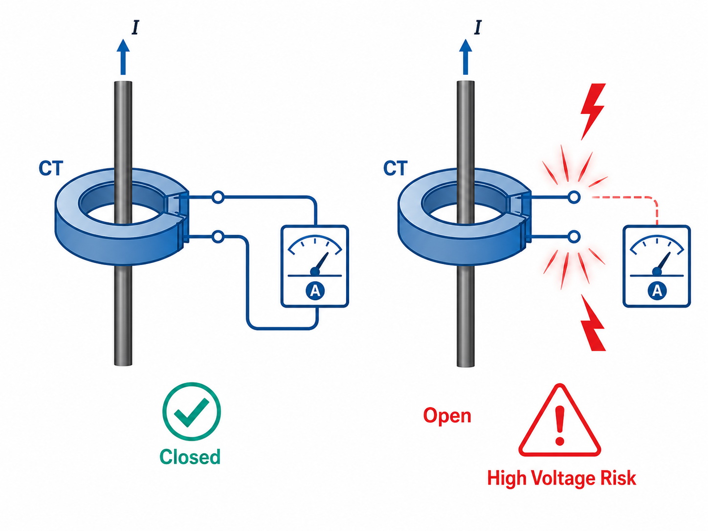
Why Must a Current Transformer Secondary Circuit Never Be Opened?
A current transformer secondary must remain closed or be safely short-circuited whenever primary current is flowing.
Under normal operation, secondary current opposes the magnetic flux created by the primary conductor. If the secondary circuit is opened, the secondary current falls to zero and the core flux can rise sharply. This may generate a dangerous voltage across the open terminals.
Possible consequences include:
- Electric shock or arcing
- Insulation breakdown
- Current-transformer overheating
- Core saturation and permanent accuracy loss
- Damage to meters or relays
- Incorrect protection operation
Before disconnecting a meter or relay, technicians should short the CT secondary through an approved test switch or shorting terminal block. A voltage transformer follows the opposite rule: its secondary can normally operate with little or no load, but it must be protected against a short circuit.
What Is the Secondary Circuit in an X-Ray Machine?
The secondary X-ray circuit is the high-voltage path that supplies the X-ray tube. It normally includes the high-voltage transformer secondary, rectification stage, tube-current measurement circuit, high-voltage cables, and X-ray tube.
The transformer increases voltage so electrons can accelerate from the cathode toward the anode. When they strike the anode target, a small portion of their energy becomes X-rays, while most becomes heat.
Tube voltage affects beam energy and penetration. Tube current affects the number of electrons crossing the tube and therefore the X-ray output. The filament circuit is separate and heats the cathode filament before the high-voltage exposure begins.
PCB and PCBA assemblies used in X-ray equipment may require:
- Large isolation distances and controlled leakage current
- Corona and partial-discharge control
- Accurate current feedback
- Shielding, grounding, and thermal monitoring
- High-voltage connectors
- Conformal coating or potting
- Documented production traceability
These requirements should be defined before PCB layout and material selection. A standard low-voltage control-board design cannot simply be reused for a high-voltage generator section.
What Is the Secondary Ignition Circuit in a Vehicle?
The secondary ignition circuit is the high-voltage path between the ignition coil secondary winding and the spark plug.
The vehicle electrical system energizes the coil primary. When the primary current is switched off quickly, the collapsing magnetic field induces a much higher voltage in the secondary winding. This voltage travels through the coil output and across the spark-plug gap.
The required firing voltage depends on:
- Spark-plug gap and electrode wear
- Cylinder pressure and air-fuel mixture
- Coil condition
- Moisture or contamination
- Cable, boot, and ground-path resistance
A primary/secondary ignition circuit fault code does not always mean the coil itself has failed. The connector, wiring harness, spark plug, ECU driver, power supply, and ground connection should also be checked.
Resistance testing can help with some conventional ignition coils. It is less reliable on modern coils that contain internal diodes or electronic control components. Waveform testing under load often gives a more useful diagnosis.
What Is the Secondary Circuit in a Potentiometer?
In a laboratory potentiometer, the primary circuit produces a stable potential gradient along the potentiometer wire.
The secondary circuit contains the unknown voltage source, galvanometer, and sliding contact. The contact is moved until the galvanometer shows zero deflection.
At the balance point, almost no current is drawn from the source being measured. This reduces loading error and allows the unknown electromotive force to be determined from the balance length.
Reliable measurement requires correct polarity, stable primary current, clean contact surfaces, a sensitive galvanometer, secure terminals, and a balance point within the available wire length. This laboratory meaning should not be confused with a transformer secondary winding.
How Are Secondary Circuits Tested?
The test method should match the circuit function.
| Test | Main Purpose | Typical Application |
|---|---|---|
| Continuity | Finds open wiring or poor connections | Harnesses, coils, relay wiring |
| Resistance | Checks winding or conductor condition | Transformers and conventional ignition coils |
| Voltage | Confirms operating output | Power and control circuits |
| Load test | Checks regulation and heating | Transformer outputs and DC supplies |
| Insulation resistance | Measures leakage through insulation | Isolated and high-voltage circuits |
| Dielectric withstand | Verifies insulation strength | Industrial, medical, and transformer assemblies |
| Polarity | Confirms terminal orientation | CTs, VTs, and multi-winding transformers |
| Ratio test | Verifies transformation ratio | Power and instrument transformers |
| Functional test | Confirms complete system behavior | PCBA and control panels |
| Secondary injection | Verifies relay settings and trip logic | Protection systems |
Secondary injection testing applies a controlled current or voltage directly to a protection relay or electronic trip unit. It can verify pickup values, time delays, alarm outputs, and trip commands without applying full current to the primary conductor.
However, it does not always verify the complete measurement path. CT ratio, CT polarity, primary wiring, and field connections may require primary injection or separate inspection.
For PCBA production, a useful functional test specification should define input conditions, output voltage range, load current, ripple limit, protection thresholds, connector states, test duration, and pass/fail tolerances. Without measurable acceptance limits, an assembly factory cannot build a repeatable test fixture or produce consistent records.
What Are Common Secondary Circuit Faults?
Typical faults include:
- Open winding, broken wire, or shorted winding turns
- Reversed polarity or incorrect transformer ratio
- Loose terminals or cracked solder joints
- Wrong connector pinout
- Overloaded rectifiers or underrated capacitors
- Excessive output ripple
- Ground loops or insufficient insulation spacing
- Relay contact failure
- Open CT secondary
- Incorrect CT or VT ratio
- Miswired relay inputs
A correct no-load voltage does not prove that the circuit is healthy. A high-resistance connection or damaged winding may appear normal without load but collapse or overheat when current is applied.
Intermittent faults may require thermal cycling, vibration, connector movement, waveform analysis, or extended operation under realistic load.
What PCB Design Factors Matter in a Secondary Circuit?
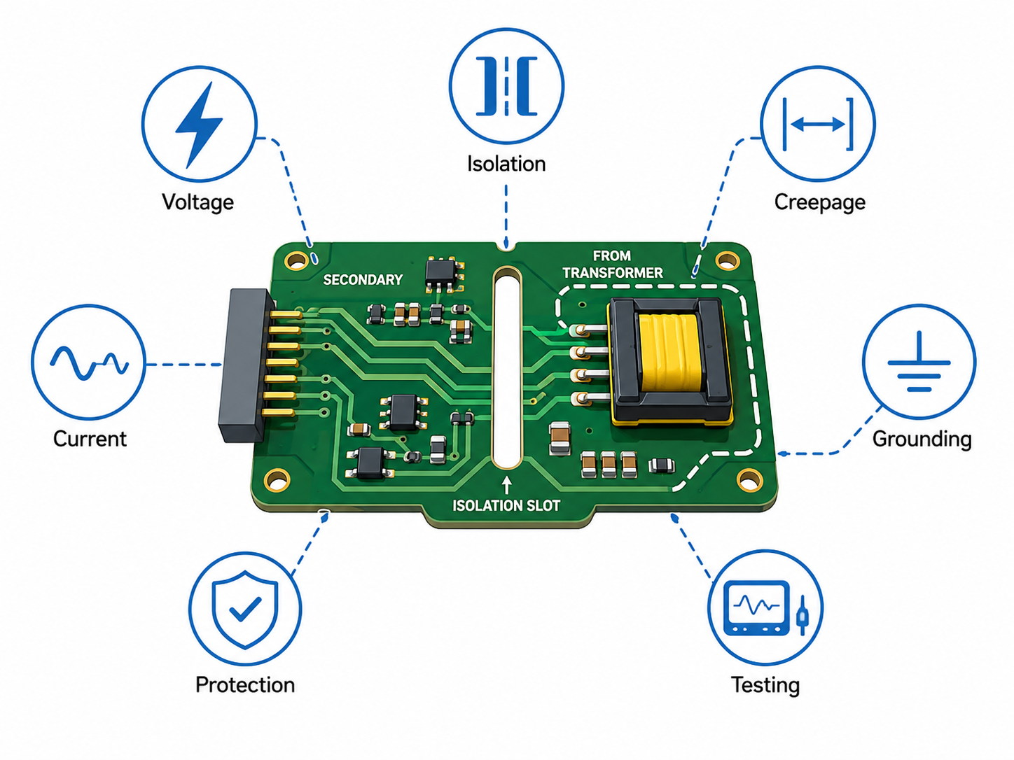
The PCB must be designed for the actual electrical stress. First determine whether the circuit is low-voltage, mains-referenced, floating, isolated, high-current, or high-voltage.
| Design Factor | Information Required |
|---|---|
| Working voltage | RMS, DC, peak, and transient voltage |
| Current | Continuous, startup, pulse, and fault current |
| Isolation | Functional, basic, supplementary, or reinforced |
| Creepage and clearance | Standard, pollution degree, material group, and altitude |
| Copper capacity | Copper weight, trace width, airflow, and temperature rise |
| Rectification | Forward current, surge current, and reverse-voltage margin |
| Filtering | Capacitance, ESR, ripple current, and output ripple |
| Grounding | Floating output, chassis, protective earth, or signal ground |
| Protection | Fuse, PTC, TVS, current limit, or secondary breaker |
| Thermal design | Transformer, diode, regulator, MOSFET, and connector losses |
| Testing | Load, ripple, insulation, hipot, and functional limits |
| Documentation | Schematic, BOM, winding data, and test instructions |
For isolated circuits, the layout must maintain the isolation barrier. Copper pours, vias, mounting holes, test pads, component bodies, and connector pins must not reduce the required spacing.
Isolation slots may increase creepage distance, but the slot width and routing tolerance should be confirmed against the PCB manufacturing capabilities. Solder mask must not be treated as the only safety insulation unless the applicable standard explicitly permits it.
High-current outputs may require wider traces, heavier copper, parallel layers, multiple vias, copper inlays, busbars, or external cables.
For quotation, buyers should provide:
- Gerber or ODB++ files and drill files
- Fabrication drawing, stackup, and copper requirements
- BOM with manufacturer part numbers
- Placement file and assembly drawing
- Transformer specification
- Input and output ratings
- Isolation and hipot requirements
- Test procedure and acceptance limits
- Prototype quantity and production forecast
EBest Circuit, also known as Best Technology, can review the PCB fabrication data, transformer pinout, assembly files, isolation requirements, and functional test conditions together. This combined review helps identify mismatched footprints, inadequate spacing, unclear connector definitions, and missing test criteria before production.
FAQs About Secondary Circuits
1. What is a secondary circuit in simple terms?
It is the part of an electrical system that receives converted power, measurement signals, or control information from a primary circuit.
2. Is a secondary circuit always electrically isolated?
No. Separate transformer windings can provide galvanic isolation, but autotransformers and circuits with shared grounds may not.
3. Is the secondary side of a transformer AC or DC?
A transformer winding produces AC. Rectifiers, filters, and regulators are required when the final output must be DC.
4. Can a transformer secondary circuit be left open?
A conventional power or voltage transformer can usually operate without a load if the manufacturer permits it. A current transformer secondary must not be left open while primary current is flowing.
5. Why must a current transformer secondary remain closed?
An open CT secondary can generate dangerous voltage, overheat the core, damage insulation, and affect measurement accuracy.
6. What is the difference between a secondary circuit and a control circuit?
A control circuit operates relays, contactors, breakers, or logic devices. It may be powered by a transformer secondary, but not every secondary circuit is a control circuit.
7. What are the three main circuits in an X-ray machine?
They are commonly described as the primary circuit, high-voltage secondary circuit, and filament circuit.
8. What voltage is present in an ignition coil secondary circuit?
The voltage varies with coil design and the level required to bridge the spark-plug gap. It is much higher than the vehicle battery voltage.
9. What is secondary injection testing?
It applies controlled current or voltage directly to a protection relay or trip unit to verify settings, timing, alarms, and trip outputs.
10. How do you identify a secondary circuit fault?
Check the source, winding ratio, continuity, polarity, voltage under load, insulation, protection devices, connectors, and final load in sequence.
Conclusion
A secondary circuit may provide low-voltage power, operate protection equipment, carry measurement signals, or generate high voltage for an ignition or X-ray system. Its design requirements depend on actual voltage, current, isolation, grounding, protection, and test conditions—not simply on the word “secondary.”
For a PCB or PCBA quotation involving transformer outputs, isolated controls, protection electronics, or high-voltage sections, send the complete design package to sales@bestpcbs.com. Clear electrical ratings and test criteria will support a more accurate engineering review and quotation.







