





power control systems measure electrical conditions, compare them with defined limits, and command devices that regulate or disconnect power. Their hardware may manage an inverter, battery, EV charger, motor drive, smart panel, or industrial load. Reliable operation depends on the control algorithm and on a PCB that can sense accurately beside noisy, high-energy switching circuits.
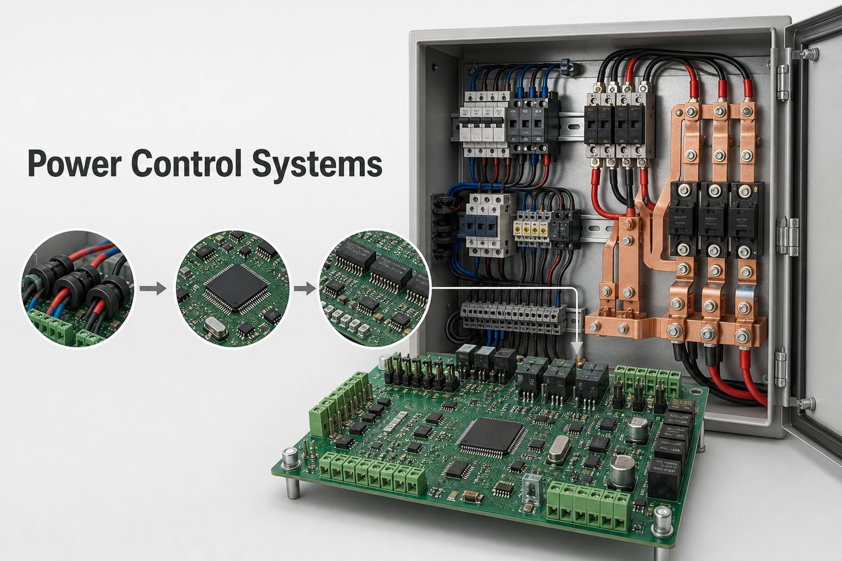
This guide follows the complete chain: measurement, decision, actuation, protection, PCB layout, assembly, and production test. It also separates the system-level definition from the practical work required to build its electronic controller.
What Are Power Control Systems?
A power control system is an active electronic system that keeps current, voltage, power, temperature, or energy flow within defined operating limits. It uses feedback rather than relying only on a passive fuse or circuit breaker. A breaker remains essential protection, but a controller can respond before a hard trip becomes necessary.
A typical system performs five functions:
- Measure: acquire current, voltage, temperature, frequency, and equipment status.
- Decide: compare measurements with limits, operating modes, and priorities.
- Act: control relays, contactors, MOSFETs, IGBTs, inverters, or connected loads.
- Protect: enter a safe state when sensing, communication, or power hardware fails.
- Report: communicate operating data, alarms, and service information.
The term can describe one controller board or several coordinated devices. The engineering boundary should therefore be stated clearly: which conductors are measured, which sources or loads are controlled, and what happens when a signal becomes invalid.
How Does a Power Control System Work?
The system operates as a closed control loop. Sensors create low-level signals from the electrical installation. Analog front ends filter and scale those signals, while isolation protects the low-voltage controller from higher-energy domains. Firmware then decides whether to maintain, reduce, redirect, or disconnect power.
- Sensors sample current, bus voltage, temperature, and equipment state.
- The analog front end filters noise and presents safe signals to an ADC or digital sensor interface.
- The processor validates the data and calculates the present operating condition.
- Control logic applies limits, priorities, timing, hysteresis, and fault rules.
- Drivers energize relays, contactors, or semiconductor switches.
- Feedback confirms that the command produced the expected result.
The last step is easy to overlook. A command alone does not prove that a contactor closed, an inverter reduced output, or a load disconnected. Independent feedback helps detect welded contacts, open sensors, stalled communication, and unexpected power flow.
What Is Inside a Power Control Unit?
A power control unit combines sensing, computation, communications, and output control. The exact components depend on voltage, current, switching speed, safety requirements, and whether the unit directly handles power or only commands external equipment.
| Functional block | Typical hardware | Main design concern |
| Measurement | Shunts, Hall sensors, transformers, dividers, temperature sensors | Accuracy, bandwidth, isolation, and fault range |
| Analog front end | Amplifiers, filters, comparators, isolated modulators | Noise rejection and stable reference paths |
| Control | MCU, DSP, FPGA, memory, watchdog | Deterministic response and safe startup |
| Actuation | Gate drivers, relay drivers, contactor coils, PWM outputs | Drive strength, timing, isolation, and fault shutdown |
| Communications | CAN, RS-485, Ethernet, wireless or isolated serial links | EMC robustness and loss-of-link behavior |
| Auxiliary power | DC-DC converters, LDOs, isolated bias supplies | Sequencing, noise, hold-up, and thermal margin |
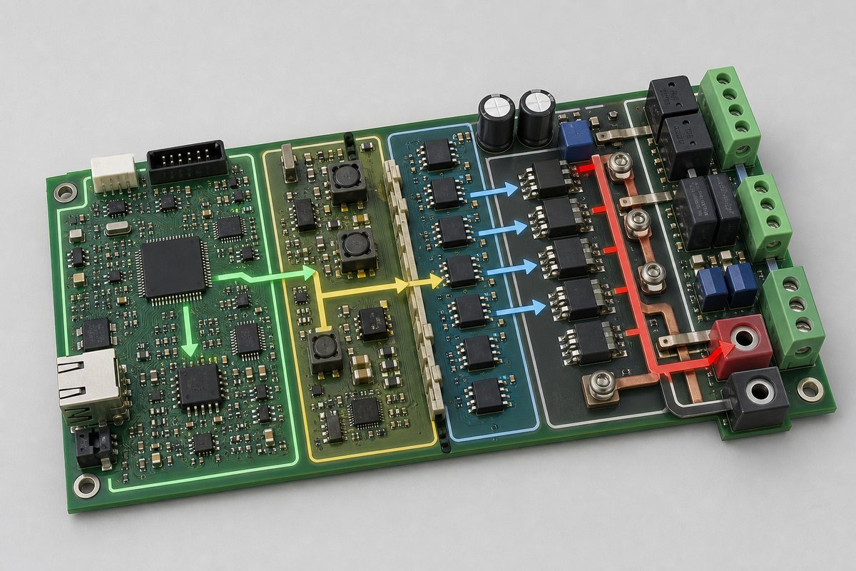
Partition the design by energy and signal function before routing. A clear block diagram should identify every power domain, ground reference, isolation barrier, sensor reference point, and independent shutdown path.
How Do Residential Power Control Systems Differ?
Residential power control systems often coordinate a limited service capacity with new loads and local energy sources. Examples include EV charging, solar inverters, battery storage, heat pumps, water heaters, and smart load panels.
The controller may:
- Limit aggregate current at a service, feeder, or busbar.
- Reduce EV charging when other household loads rise.
- Control import or export from an inverter and battery system.
- Shed noncritical loads in a defined priority order.
- Restore loads gradually after capacity becomes available.
For North American distributed-energy applications, the project team may need to evaluate relevant electrical-code provisions and product requirements such as UL 3141. Compliance scope depends on the final function and installation, so it should be defined before schematic and PCB decisions are frozen.
What Is the Role of a Power Control Panel?
A power control panel is the physical assembly that houses the controller, protective devices, switching elements, terminals, wiring, and user interfaces. The PCB is one part of this larger electrical and mechanical system.
Panel and PCB design must agree on:
- Nominal and maximum conductor current
- Short-circuit and overvoltage exposure
- Connector type, wire size, torque, and service access
- Clearance, creepage, insulation, and protective-earth strategy
- Airflow, enclosure temperature, contamination, and condensation
- Contactor coil energy, flyback suppression, and auxiliary contacts
- Emergency-stop and manual-disconnect behavior
A board can pass bench tests and still fail inside an enclosure if cable routing couples switching noise into sensors or if panel temperature removes the PCB’s thermal margin. Review the board, harness, enclosure, and load as one assembly.
How Do Power Electronics and Control Systems Share a PCB?
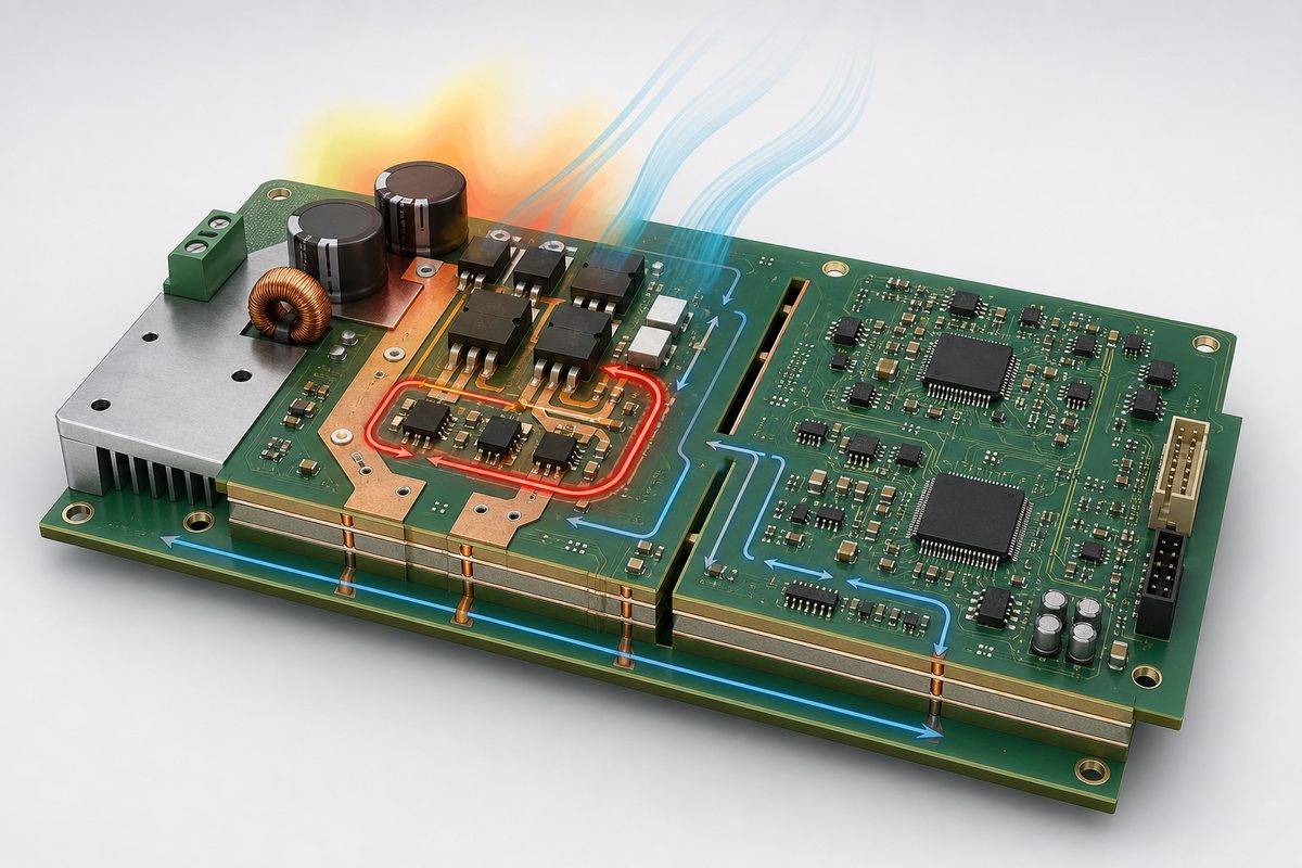
In power electronics and control systems, high-current switching and low-level measurement often occupy the same PCB. The two functions need short connections, but they should not share uncontrolled return paths.
Use these layout priorities:
- Place switching devices, gate drivers, and local bypass capacitors as one compact cell.
- Minimize high di/dt loop area and keep switch nodes away from sensing and communications.
- Route shunt measurements as matched Kelvin connections from the resistor terminals.
- Separate power returns from analog references, then join them only at the intended point.
- Preserve isolation with controlled creepage, clearance, slots, and component placement.
- Give fault and shutdown paths a direct route that does not depend on normal firmware traffic.
For a deeper look at copper, spacing, and heat, use these high-power PCB design considerations. If the current requirement exceeds practical standard copper, evaluate whether a heavy copper PCB is appropriate instead of widening traces without checking fabrication and thermal limits.
Which PCB Design Rules Matter Most?
Begin with the actual fault and operating envelope, not only nominal power. The PCB must remain predictable during startup, load steps, brownouts, communication loss, sensor faults, and shutdown.
- Current capacity: size copper using current, allowable temperature rise, copper weight, layer position, airflow, and terminal limits.
- Thermal paths: move heat through copper spreading, thermal vias, heat sinks, or metal structures without overheating nearby sensors.
- Isolation: define working voltage, transient category, pollution environment, material group, and required insulation before placement.
- Measurement integrity: protect ADC references and sense lines from switch-node electric fields and shared ground drop.
- EMC control: reduce loop area at the source, add filtering at interfaces, and provide a controlled return for common-mode currents.
- Fail-safe outputs: choose default states for reset, unpowered, disconnected, and watchdog-expired conditions.
- Test access: expose safe points for rails, communications, sensing, programming, and fault injection.
The auxiliary rails deserve the same discipline as the power path. This power supply circuit design guide covers regulation, filtering, protection, and thermal choices that support stable control electronics.
How Are Power Control PCBs Manufactured and Tested?
Manufacturing planning should start before layout release. Large copper areas, mixed component sizes, heavy terminals, selective soldering, heat sinks, and isolation slots can affect panelization, stencil design, reflow balance, soldering sequence, and inspection access.
A controlled build flow includes:
- DFM review: confirm stackup, copper distribution, drills, slots, clearances, solder-mask dams, and panel rails.
- Assembly planning: define stencil apertures, thermal profiles, secondary soldering, mechanical fastening, and cleaning needs.
- Inspection: use AOI, X-ray where justified, polarity checks, torque records, and isolation-area inspection.
- Electrical test: verify shorts, opens, programming, rails, sensor offsets, communication, and output states.
- Functional test: apply controlled loads and faults to confirm limits, timing, shutdown, recovery, and alarm reporting.
- Thermal validation: test the worst credible operating condition inside the intended enclosure or a representative fixture.
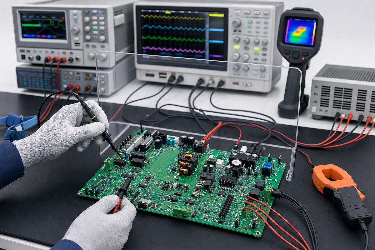
A first-article build should create evidence, not just a pass label. Store test limits, measured values, firmware version, calibration data, serial number, and the exact BOM and PCB revision. The broader PCB assembly process also needs component control and repeatable inspection criteria.
What Should Be Included in the Manufacturing Package?
A quote or production package should remove ambiguity about both the PCB and the system. Include:
- Gerber or ODB++ data, NC drill files, stackup, and fabrication drawing
- BOM with approved alternates and lifecycle constraints
- Centroid data, assembly drawings, polarity notes, and programming files
- Maximum voltage, continuous current, transient current, and fault energy
- Isolation and spacing requirements with the basis for each barrier
- Connector, terminal, heat-sink, fastener, coating, and enclosure interfaces
- Functional test limits, calibration procedure, fixtures, and acceptance criteria
- Firmware version control and safe-state behavior
Do not hide critical limits only in firmware or a schematic note. Put system-level constraints in a controlled specification and repeat the manufacturing-critical items on the relevant drawing.
What Are Common Power Control System Design Mistakes?
- Designing only for nominal load: startup and fault energy can dominate copper, connector, and switching requirements.
- Sharing noisy returns: ground drop can corrupt current readings and trigger unstable control.
- Using one feedback path: a failed sensor or welded contact may go undetected.
- Treating isolation as a symbol: PCB geometry, components, coating, slots, and assembly cleanliness all matter.
- Leaving safe state undefined: reset, brownout, and communication loss then produce unpredictable outputs.
- Testing without realistic heat: an open-bench pass may not represent the final enclosure.
- Changing parts without revalidation: relays, sensors, drivers, and MOSFETs can alter timing, loss, and fault behavior.
A useful design review asks what happens when each input is wrong, each communication link is lost, and each controlled device does not follow its command.
What Are Frequently Asked Questions About Power Control Systems?
What is the difference between power control and power protection?
Control actively regulates or redirects power during normal operation. Protection interrupts or limits hazardous conditions. A reliable design uses coordinated control and independent protection.
Is a power control system the same as an energy management system?
They can overlap, but an energy management system may optimize cost or scheduling while a PCS can have a direct overload-limiting function. Define the required safety and control boundary for the product.
Can one PCB handle both sensing and high-power switching?
Yes, when zoning, isolation, return paths, copper, thermal design, and EMC controls are planned together. Separate boards may be better when voltage, heat, or service constraints demand physical separation.
Why is Kelvin routing used for current sensing?
Kelvin traces connect directly to the sense element terminals so load-current voltage drop in shared copper does not become measurement error.
When is heavy copper useful?
It can support higher current, heat spreading, and robust power connections. It also affects etching, spacing, vias, soldering, cost, and stackup, so it must be reviewed with the fabricator.
Does every power control PCB need galvanic isolation?
No. The need depends on voltage domains, grounding, accessible circuits, communication interfaces, and safety requirements. Functional separation and safety isolation are not interchangeable.
What should happen if communication is lost?
The design should enter a documented safe state, maintain a locally safe limit, or shut down according to the hazard analysis. It should not depend on an unavailable remote command.
How is a power control PCBA tested?
Typical coverage includes programming, rail checks, sensor calibration, communications, output control, controlled load tests, injected faults, isolation checks, and thermal validation.
What information is needed for a PCB quote?
Provide fabrication data, stackup, copper, materials, dimensions, finish, BOM, assembly files, quantity, test scope, and the voltage, current, isolation, and thermal requirements that affect manufacturing.
Can a manufacturer choose the safe-state logic?
The product owner must define it. The manufacturer can review feasibility and testability, but reset, fault, and shutdown behavior belongs in the approved system specification.
How Do You Move From Architecture to a Reliable PCBA?
Start with the control boundary and fault response. Then partition sensing, computation, isolation, actuation, communications, and auxiliary power before placing components. Validate current paths, switching loops, measurement references, heat flow, and enclosure conditions as one system.
If you are preparing a new controller, send the schematic, PCB data, BOM, voltage and current envelope, isolation requirements, mechanical interfaces, firmware, and test limits. Best Technology can review the fabrication and assembly risks around your power control systems design before prototype tooling and production testing are fixed.







