PCB manufacturing software helps turn PCB design data into production-ready information for fabrication, assembly and quality control. It connects layout files, DFM checks, BOM data, drill files, panel requirements and assembly information before a board reaches the factory floor.
For OEM, ODM, sample development and mass production projects, the right software reduces redesign risk, shortens review time and improves communication between the design side and the PCB manufacturer. However, software alone cannot guarantee manufacturability. The best result comes from combining software checks with real factory capability, DFM review and production feedback.
What Is PCB Manufacturing Software?
PCB manufacturing software is used to check, prepare and manage PCB data before fabrication and assembly. It may include PCB making software, CAM software, DFM checking tools, DFA analysis tools, quotation systems and production planning modules.
Its main role is simple: find manufacturing risks before copper, laminate, solder mask, drilling, plating and SMT assembly begin. A good system can review Gerber, ODB++, IPC-2581, drill files, netlists, BOM and pick-and-place data.
In real production, PCB manufacturing software does not replace engineering judgment. It supports decision-making by showing where a PCB may fail, cost more, or delay delivery.
Why Is PCB Manufacturing Software Important for Electronics Manufacturing?
PCB manufacturing software is important because small design errors can create large production losses. A missing drill file, narrow spacing, poor annular ring, wrong pad size or unclear BOM can stop the entire order.
For electronics manufacturing, the software improves early visibility. It helps detect DFM, DFA, file, cost and assembly risks before the PCB moves into production. This reduces engineering back-and-forth and helps avoid expensive respins.
For overseas buyers working with a China source factory, it also improves communication. Clear data, reports and revision control make it easier to confirm requirements across time zones, languages and supply chains.
What Software Is Used to Make PCBs?
Several types of software are used to make PCBs, but they serve different purposes. PCB design software creates the circuit and layout, while PCB manufacturing software checks whether the design can be produced reliably.
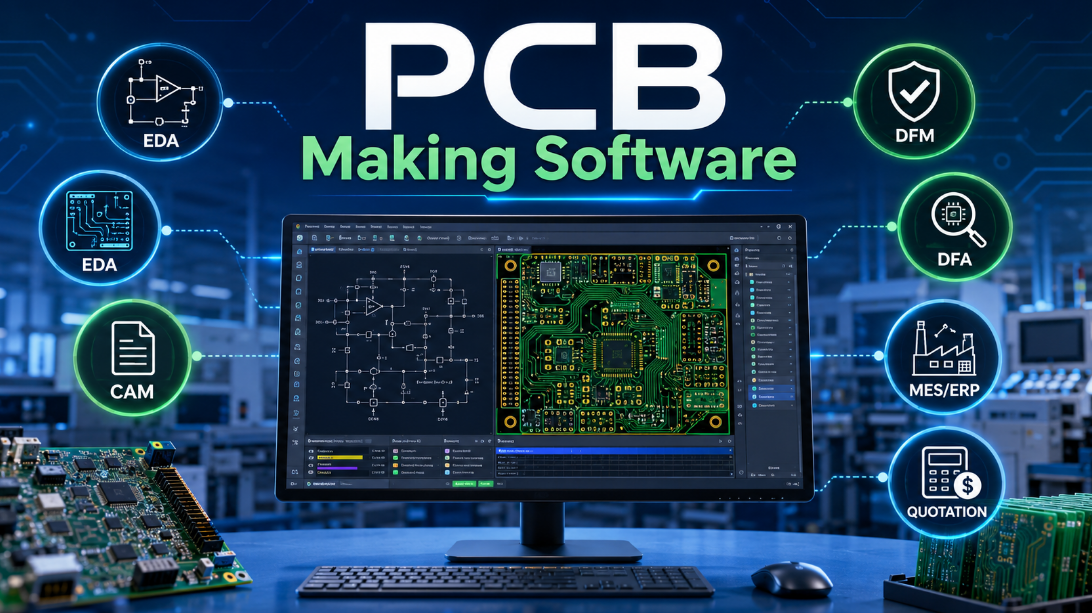
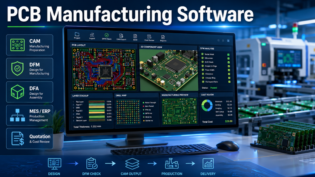
Common software categories include:
- EDA software for schematic design, PCB layout and routing
- CAM software for manufacturing file preparation
- DFM software for fabrication risk checking
- DFA software for assembly risk checking
- MES or ERP systems for production scheduling and tracking
- Quotation software for cost estimation and lead time review
For a simple PCB, free PCB making software may be enough for early layout. For industrial, medical, automotive, RF or high-density boards, professional DFM and factory review become much more important.
How Does DFM Software Improve PCB Design and Manufacturing?
DFM software improves PCB design and manufacturing by checking whether the layout matches real production capability. It reviews the features that often cause fabrication defects.
Key DFM checks usually include:
- Minimum trace width and spacing
- Drill-to-copper clearance
- Annular ring size
- Solder mask bridge risk
- Copper-to-board-edge clearance
- Aspect ratio and hole reliability
- Slot, routing and outline accuracy
- Panelization and fiducial requirements
These checks help detect weak points before production. As a result, DFM software can reduce scrap, rework, schedule delays and repeated file revisions.
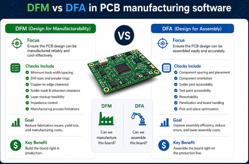
What Is the Difference Between DFM and DFA in PCB Manufacturing Software?
DFM checks whether the PCB can be fabricated reliably, while DFA checks whether components can be assembled correctly. Both are important, but they focus on different risks.
| Item | DFM | DFA |
|---|---|---|
| Focus | Bare PCB fabrication | Component assembly |
| Checks | Copper, holes, mask, outline | Pads, spacing, BOM, polarity |
| Main Risk | Board manufacturing defects | SMT and soldering defects |
| File Data | Gerber, drill, stackup | BOM, CPL, assembly drawing |
| Result | Better bare board yield | Better PCBA yield |
A PCB may pass DFM but still fail DFA if component spacing, polarity marking, pad size or thermal balance is poor. For production-ready projects, both checks should be completed before ordering.
What Features Make PCB Design Software Suitable for Manufacturing DFM and DFA?
PCB design software becomes suitable for manufacturing when it supports rule-driven layout, file accuracy and early production review. The tool should not only draw a PCB, but also help prevent production problems.
Important features include:
- Custom design rules based on factory capability
- 3D clearance and mechanical interference review
- Integrated DRC, DFM and DFA checks
- Controlled impedance and stackup support
- Accurate Gerber, ODB++ or IPC-2581 output
- BOM and pick-and-place export
- Revision control and release package management
- Assembly drawing and polarity marking support
For manufacturing DFM, the most useful software is not always the most expensive one. The key is whether the rules match the real PCB factory process.
How Can Software Prevent PCB Redesign Costs in Electronics Manufacturing?
Software prevents PCB redesign costs by finding errors before production files are released. Most redesign costs come from late-stage problems that were not visible during schematic or layout review.
Common preventable issues include:
- Wrong footprint or pad size
- Missing thermal relief
- Insufficient copper clearance
- Poor via structure
- Inaccurate board outline
- Unclear layer stackup
- BOM mismatch
- Incorrect component polarity
When these issues are detected early, the customer can revise the file once instead of repeating prototype production. For sample development, this protects schedule. For mass production, it protects cost, yield and delivery stability.
What Materials and Manufacturing Data Should the Software Check?
PCB manufacturing software should check both layout data and material-related production requirements. A board may look correct electrically but still create problems if the material, stackup or surface finish is not suitable.
Important data includes:
- Base material such as FR4, high-TG FR4, Rogers, polyimide or ceramic
- Copper thickness and finished copper requirement
- Board thickness and tolerance
- Surface finish such as HASL, ENIG, OSP or immersion silver
- Solder mask color and opening accuracy
- Controlled impedance requirements
- Stackup, prepreg and core structure
- Thermal, RF or high-speed performance requirements
Material checks matter because manufacturing limits change with laminate type, copper weight, board thickness and layer count.
What Is the PCB Manufacturing Software Review Process?
The review process should move from file completeness to production risk, then from engineering confirmation to factory release. This keeps the workflow clear and reduces repeated communication.
First, the software checks whether all required files are included, such as Gerber, drill, netlist, BOM, pick-and-place file and assembly drawing. Then it reviews fabrication risks, including spacing, hole size, copper clearance, solder mask, outline and stackup.
After that, DFA checks confirm pad geometry, component spacing, polarity, package consistency and soldering risk. Finally, the engineering team confirms special requirements before releasing the project to prototype or mass production.
The best process combines automatic software review with manual engineering confirmation.
What Are the Advantages and Limitations of PCB Manufacturing Software?
PCB manufacturing software improves production preparation, but it cannot replace a real factory review. It is most valuable when used as part of an engineering workflow.
Main advantages include:
- Faster file checking
- Lower redesign risk
- Better communication
- Earlier cost visibility
- More stable prototype transfer
- Improved assembly preparation
- Clearer production documentation
However, there are also limits:
- Generic rules may not match every factory
- Software may miss process-specific risks
- Complex RF, HDI and high-voltage boards still need expert review
- Incorrect input data can create misleading results
- Free PCB making software may lack advanced manufacturing checks
The conclusion is simple: software improves speed, but factory capability confirms feasibility.
Where Is PCB Manufacturing Software Commonly Used?
PCB manufacturing software is used across industries where reliability, delivery and repeatable production matter. It is especially useful when the PCB has tight tolerances, complex assembly or high compliance requirements.
Common application areas include:
- Industrial control equipment
- IoT and wireless devices
- Automotive electronics
- Medical equipment
- Telecom and networking hardware
- Consumer electronics
- Power supply systems
- Aerospace and defense-related electronics
- Smart home and access control products
For low-volume samples, software helps speed up review. For high-volume orders, it helps protect yield and cost stability.
What Common Failures Can PCB Manufacturing Software Help Find?
PCB manufacturing software can help find many early-stage problems, especially those linked to fabrication and assembly readiness. These failures are often expensive when discovered after production starts.
Typical issues include:
- Open or short risk caused by poor spacing
- Breakout risk from weak annular rings
- Solder bridging from narrow mask dams
- Tombstoning risk from unbalanced pads
- Assembly mismatch from wrong footprints
- Poor solderability from unsuitable finish choice
- Warping risk from unbalanced copper
- Impedance deviation from unclear stackup
- Test failure caused by missing test points
In factory practice, many delays are not caused by manufacturing speed. They are caused by unclear, incomplete or risky design data.
How Should Buyers Choose PCB Manufacturing Software or Factory Review Support?
Buyers should choose software or factory review support based on project complexity, production volume and quality risk. A free tool may be acceptable for simple prototypes, but industrial projects require deeper checking.
Practical selection points include:
- Match software rules with real factory capability
- Confirm support for Gerber, ODB++, IPC-2581, BOM and CPL files
- Check whether DFM and DFA are both included
- Ask for visual reports and clear issue locations
- Confirm controlled impedance and stackup review support
- Review whether the supplier can support prototype and mass production
- Avoid relying only on automatic pass/fail results
- Choose a manufacturer that explains risks before quoting blindly
For global buyers sourcing from China, a factory with engineering review support is often more useful than software alone.
How Does a China PCB Factory Use Software for Global OEM and ODM Projects?
A China PCB source factory uses PCB manufacturing software to improve file review, quotation accuracy, production planning and quality control for overseas projects. The goal is not to pretend to be local, but to support global delivery with clear engineering communication.
For US and European projects, the focus is often compliance, documentation, long-term reliability and stable repeat orders. For Southeast Asian projects, buyers often care more about flexible quantities, cost control and faster sample-to-batch transition.
As a direct manufacturer, EBest supports OEM, ODM, sample development, custom PCB, PCBA and mass production projects with engineering review before production. This helps overseas buyers reduce communication gaps and avoid unnecessary redesigns.
FAQs About PCB Manufacturing Software
Q1: Is PCB manufacturing software the same as PCB design software?
A1: No. PCB design software creates schematics and layouts, while PCB manufacturing software checks whether the PCB can be fabricated, assembled and tested. Both tools work together, but they solve different problems.
Q2: Can free PCB making software be used for production orders?
A2: Free PCB making software can be used for simple boards, early learning and basic prototypes. For industrial orders, factory DFM review is still important because free tools may not match the manufacturer’s real process limits.
Q3: What files should be uploaded for a PCB manufacturing software check?
A3: A complete check usually uses Gerber, drill files, netlist, BOM, pick-and-place file, stackup notes and assembly drawing. Missing files can delay quotation, DFM review and production release.
Q4: Does PCB assembly manufacturing software check component issues?
A4: Yes, assembly-focused software can check BOM consistency, component placement, polarity, pad size, spacing and soldering risk. DFA checking is especially useful before SMT assembly and mixed-technology production.
Q5: Can software calculate PCB manufacturing cost automatically?
A5: Some quotation software can estimate cost from layer count, size, material, copper thickness, surface finish and quantity. However, special processes, tolerance requirements and assembly complexity still require manual confirmation.
Q6: What is the biggest mistake when using PCB manufacturing software?
A6: The biggest mistake is trusting a generic “pass” result without checking factory capability. A design may pass software rules but still exceed a specific manufacturer’s equipment, material or yield limits.
Q7: Is DFM software useful for prototype PCB orders?
A7: Yes. Prototype orders benefit from DFM because early mistakes are easier and cheaper to fix. One DFM review before sampling can prevent repeated prototypes, delayed testing and unnecessary redesign cost.
Q8: Does PCB manufacturing software support high-speed PCB projects?
A8: Some tools support impedance, stackup and spacing checks, but high-speed boards still require expert review. Signal integrity, return path, via structure and material selection cannot be judged by basic rules alone.
Q9: How does software help reduce PCB assembly defects?
A9: Software helps by checking footprint accuracy, component spacing, pad balance, polarity marks and BOM data. These checks reduce solder bridging, tombstoning, wrong placement and rework during PCBA production.
Q10: What is the difference between DRC and DFM?
A10: DRC checks whether the layout follows design rules inside the software. DFM checks whether the PCB can be manufactured reliably. DRC is design-focused, while DFM is factory-focused.
Q11: Can PCB manufacturing software replace supplier communication?
A11: No. Software improves communication, but it cannot replace technical discussion with the manufacturer. Special materials, tight tolerances, impedance, HDI, RF and assembly risks should still be confirmed by engineers.
Q12: What should buyers ask before choosing a PCB manufacturer?
A12: Buyers should ask about DFM review, material options, quality standards, lead time, testing, assembly capability and mass production control. A reliable supplier explains risks before production, not after defects appear.
Conclusion
PCB manufacturing software is valuable because it connects design data with real production requirements. The core technical point is that DFM, DFA, file checking and engineering review should happen before fabrication and assembly begin. This reduces redesign cost, improves production yield and makes the project easier to move from sample development to mass production.
For selection, choose software and manufacturing support that match your PCB complexity, material, assembly type, quality level and production volume. For purchasing, do not rely only on a low quotation or automatic software result. A reliable China source factory should provide clear DFM feedback, practical engineering review, stable production control and global delivery support.
If you are looking for reliable OEM manufacturing, ODM production, sample development, mass production, or custom engineering solutions, please contact our engineering team for technical support and a quote: sales@bestpcbs.com.