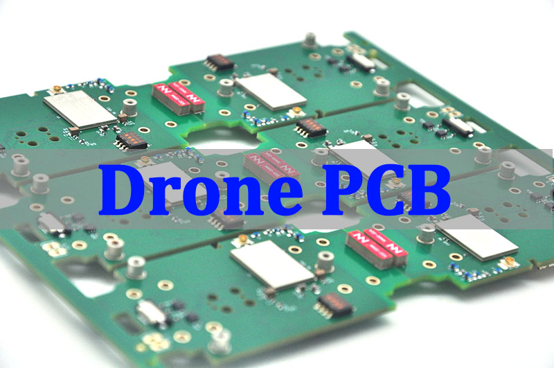
A mini drone PCB must combine flight control, sensing, power conversion, motor interfaces, radio communication, and often a camera connection within a small weight and area budget. A successful board is not simply a reduced full-size drone controller: its stackup, component placement, current paths, antenna zone, thermal behavior, firmware interfaces, and production test plan must be designed as one system.
For teams moving from concept to production, the safest path is to align schematic design, PCB fabrication, component sourcing, assembly, programming, and functional testing before the first prototype is released. This turnkey approach reduces handoff errors and gives engineers a controlled route from a compact drone electronics concept to a repeatable mini drone PCBA.
What Is a Mini Drone PCB and What Functions Does It Control?
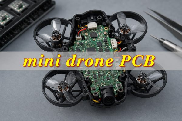
A mini drone PCB is the central flight-control platform that converts pilot or autonomous commands into stable motor output. Depending on the product architecture, one board may integrate the flight controller, receiver, power management, motor drivers, telemetry, camera control, and programming interface, or these functions may be divided across a small board stack.
The control loop reads the inertial measurement unit (IMU), estimates attitude, processes receiver commands, and updates motor outputs many times per second. Power circuits convert battery voltage into clean rails for the processor, sensors, radio, and camera. Communication ports connect devices such as a receiver, video transmitter, USB interface, or external sensor. These functions must coexist without allowing motor-switching noise or frame vibration to corrupt the measurements used for flight stabilization.
| Functional Block | Main Role | Primary Design Risk |
| Flight controller | Runs control algorithms and produces motor commands | Reset, timing error, or poor signal integrity |
| IMU and sensors | Measure motion, orientation, pressure, or altitude | Vibration and electrical noise |
| Power management | Creates stable logic, sensor, radio, and camera rails | Voltage droop, ripple, and heat |
| Motor interface | Drives brushed motors or communicates with ESCs | High-current transients and EMI |
| Receiver and radio | Receives commands and sends telemetry | Antenna detuning and RF interference |
| Camera interface | Supplies power and carries video or control signals | Noise coupling, bandwidth, and connector stress |
What Are the Main Components of a Mini Drone PCB Board?
The essential components form a complete control and power chain: a processor, motion sensors, regulated rails, motor interfaces, communication circuits, clocking, memory, and protection. The exact bill of materials depends on whether the drone uses brushed motors, separate brushless ESCs, an integrated receiver, analog video, or a digital camera.
- Processor: An MCU or SoC executes the flight firmware, sensor fusion, communications, and safety logic.
- Motion sensing: A gyroscope and accelerometer, commonly combined in an IMU, provide the measurements used for attitude control.
- Power conversion: Buck converters, LDOs, filtering components, and supervisors create stable rails and protect against battery disturbances.
- Motor control: Brushed designs may use MOSFET stages on the board, while brushless designs usually provide timer outputs or digital ESC interfaces.
- Radio connection: The mini drone receiver board may be integrated or connected through UART, SPI, or another protocol.
- Programming and debug: USB, SWD/JTAG, boot control, and accessible test pads support firmware loading and fault analysis.
- Protection: Reverse-polarity, ESD, overcurrent, and transient controls are selected according to the battery and exposed interfaces.
Component selection must consider package size, availability, peak current, startup behavior, temperature, firmware support, and assembly yield. A smaller package saves area only if the fabricator and assembler can build and inspect it consistently.
How Should a Compact Mini Drone PCB Layout Be Designed?
A compact mini drone PCB layout should follow a requirements-to-verification workflow, not begin with component placement alone. Size, weight, battery, motors, receiver, camera, firmware interfaces, thermal limits, and production tests must be defined before the stackup and routing rules are frozen.
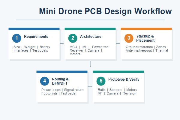
- Freeze product requirements: Confirm the board outline, mounting pattern, target weight, battery range, motor type, receiver, camera, connectors, firmware interfaces, and environmental limits.
- Build the architecture and power budget: Create the block diagram, assign MCU peripherals, define motor and communication interfaces, estimate peak current, and set voltage-rail and brownout margins.
- Verify components and footprints: Check lifecycle, package availability, thermal ratings, pin mapping, land patterns, polarity, assembly clearances, and approved substitutions before placement.
- Define stackup and design rules: Select the layer count, board thickness, copper weight, impedance targets, via structure, minimum geometry, and reference-plane strategy with the manufacturer.
- Place by mechanical and noise priority: Put the IMU near the mechanical center, keep switching power and motor outputs at the edges, reserve the antenna keepout, and align the camera, battery, debug, and motor connections with the enclosure.
- Route power and signals deliberately: Minimize high-current and switching-loop area, preserve continuous return paths, place decoupling at device pins, control high-speed interfaces, and keep sensor buses away from noisy nodes.
- Complete DFM and DFT review: Validate solder-mask clearances, stencil apertures, panel rails, fiducials, assembly access, AOI/X-ray visibility, programming pads, and functional-test points.
- Prototype, measure, and revise: Use current-limited power-up, verify rail ripple and temperature, calibrate sensors, test motors, receiver and camera together, review vibration behavior, and close findings in the next controlled revision.
During placement, organize the board by current level, noise sensitivity, mechanical location, and interface direction. Keep the IMU away from inductors, switching nodes, motor MOSFETs, mounting stress, and flexible board edges. A four-layer stackup is often a practical starting point because it can provide a solid ground plane and controlled routing. Six layers or an HDI mini drone PCB may be justified by fine-pitch packages, multiple radios, an integrated camera, or severe outline constraints, but the added complexity should solve a documented design problem.
How to Design a Lightweight Mini Drone PCB Without Sacrificing Reliability?
Reduce weight through system-level integration, not by weakening current paths, mounting points, or the laminate without analysis. A lightweight drone PCB should be optimized as a complete system: combining boards can remove connectors and cables, while a thinner board may require additional mechanical support to avoid flex-induced solder-joint or component damage.
| Weight-Reduction Choice | Benefit | Reliability Check |
| Smaller outline | Less laminate and lower mass | Confirm creepage, placement, antenna clearance, and assembly access |
| Thinner board | Direct PCB weight reduction | Analyze flex, connector load, impact, and panel handling |
| Board integration | Removes cables and connectors | Check heat concentration, noise coupling, and repairability |
| HDI interconnect | Supports dense routing and small packages | Confirm microvia structure, yield, inspection, and cost trade-off |
| Smaller components | Reduces area and component mass | Verify derating, availability, rework limits, and placement capability |
Use copper where electrical or thermal performance requires it, and remove it only after current-density and temperature-rise checks. Keep mounting zones robust, use strain relief for battery and motor wires, and avoid placing brittle components in high-flex corners. Reliability comes from balancing grams against vibration, shock, heat, and manufacturing variation.
How Should Power, Motor and Sensor Circuits Be Isolated on a Mini Drone PCB?
Use placement and controlled return paths to isolate noisy and sensitive circuits; do not rely on arbitrary ground-plane cuts. Motor current and switching nodes belong near their connectors and drivers; the IMU and its quiet supply belong away from those regions. A continuous ground reference generally gives high-frequency return current a predictable path, while poor plane splits can force current around a gap and increase loop area.
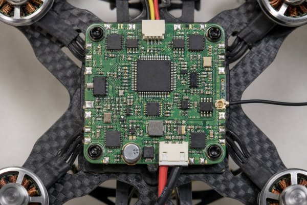
- Separate switching nodes: Keep regulator switch nodes and motor drive edges compact and away from sensor traces.
- Control battery transients: Size bulk and high-frequency decoupling for motor startup, braking, and fast load changes.
- Filter sensitive rails: Feed the IMU or analog section through a suitable low-noise rail and local decoupling network.
- Route by return current: Keep each fast signal adjacent to an uninterrupted reference and avoid unnecessary layer changes.
- Measure before release: Probe rail ripple, brownout margin, regulator temperature, and sensor noise while motors change speed.
For a 1S Li-ion or LiHV system, the design must also account for battery voltage decline and transient sag. The MCU must not reset when the motors demand a short current pulse. Validation should use the actual battery, motors, propellers, wiring, firmware, and operating modes because a bench supply alone may hide the real impedance of the power path.
How Should a Mini Drone Receiver Board and Antenna Area Be Designed?
The receiver and antenna zone needs controlled RF clearance, including a defined feed path, the manufacturer’s recommended keepout, and separation from motor wiring and switching power. Position the antenna where the final frame, battery, camera, shielding, and carbon-filled structures will not block or detune it. The board outline and enclosure are part of the antenna environment, so RF review cannot stop at the PCB file.
Use the radio or antenna vendor’s reference layout for feed geometry, matching components, ground treatment, and keepout dimensions. Keep the feed short, avoid unnecessary vias, and provide a tuning or measurement option when the antenna is printed on the PCB. If a coax connector is used, protect it from cable pull and repeated impact.
- Reserve antenna clearance: Keep copper, components, fast clocks, motor leads, and metal hardware out of the specified zone.
- Protect the RF supply: Filter the receiver rail and prevent shared impedance with high-current motor returns.
- Plan coexistence: Review receiver, telemetry, Wi-Fi, Bluetooth, and video frequencies together when several radios operate at once.
- Test in the product: Measure link quality and range with the complete frame, battery, camera, propellers, and normal motor activity.
How Should a Mini Drone Camera Circuit Board Interface Be Designed?
A mini drone camera circuit board interface must balance signal integrity and mechanical reliability. Bandwidth, power integrity, grounding, connector retention, and thermal limits must be reviewed together. An analog camera connection may emphasize clean power and controlled video return, while a digital image sensor may require controlled-impedance differential pairs, matched lengths, strict pin mapping, and careful connector selection.
Place the camera connector to support the required viewing angle without twisting the flex or cable. Protect exposed lines against ESD when handling or external access is expected. If the processor performs image capture or streaming, verify its peak current and heat dissipation under the highest frame rate and radio load, not only during idle operation.
- Confirm interface type: Define analog video, parallel camera bus, MIPI CSI-2, USB, SPI, or another interface before stackup and routing.
- Budget camera power: Include startup current, illumination changes, processing load, and video-transmitter demand.
- Control high-speed routing: Follow the device vendor’s impedance, length-matching, reference-plane, and via guidance.
- Secure the connection: Choose a connector and cable path that tolerate vibration and assembly handling.
- Verify image quality: Test for noise bands, dropped frames, overheating, and RF interference while motors operate.
What PCB Materials, Layer Counts and Surface Finishes Are Suitable for Mini Drone PCBs?
FR-4 with four layers is a practical engineering baseline, but material, thickness, layer count, and finish still depend on density, RF performance, flex, heat, and assembly pitch. Material selection should begin with the electrical and mechanical requirements rather than a generic drone label.
| Option | When It Fits | Main Trade-off |
| Standard FR-4 | General flight control and low-to-moderate speed digital circuits | Confirm Tg, loss, thickness, and mechanical performance for the actual design |
| High-Tg FR-4 | Higher process or operating thermal demand | Higher material cost than a basic FR-4 construction |
| High-frequency laminate | RF feed or antenna performance that cannot be met reliably on the chosen FR-4 | Material availability, hybrid construction, and process control |
| Rigid-flex or flex | Folded packaging or replacing cable assemblies | Bend design, coverlay, assembly support, and higher fabrication complexity |
| Four layers | Compact controller with a solid ground reference and moderate density | Routing space may be limited for integrated ESC, radio, and camera functions |
| Six layers or HDI | Fine-pitch packages, dense escape routing, or additional power/reference layers | Higher process complexity and stronger DFM requirements |
| ENIG | Fine-pitch assembly and a flat solderable surface | Finish selection must match cost, storage, and assembly needs |
| Lead-free HASL | Cost-sensitive designs with compatible pad pitch and planarity needs | Less planar than ENIG for very fine-pitch components |
Final values for board thickness, copper weight, finished hole size, impedance, solder mask clearance, and surface finish should be fixed through a stackup review with the manufacturer. RF structures, fine-pitch BGAs, via-in-pad, microvias, and thin cores require early confirmation because late substitutions can change impedance, assembly yield, and overall reliability.
How Are Mini Drone Circuit Boards Manufactured and Assembled?
Mini drone circuit board manufacturing needs a single controlled production flow from DFM review through fabrication, SMT assembly, programming, and functional test. The manufacturer first reviews the Gerber or ODB++ data, drill files, stackup, impedance notes, panel plan, BOM, centroid data, assembly drawings, and acceptance requirements.
- Engineering review: Check manufacturability, component availability, polarity, footprints, panelization, test access, and assembly risks.
- PCB fabrication: Build the multilayer structure, form holes or microvias, plate copper, image the outer layers, apply mask and finish, and electrically test the bare boards.
- Solder-paste printing: Use a suitable stencil design for fine-pitch ICs, small passives, exposed pads, and thermal balance.
- SMT placement: Control component orientation, package handling, moisture sensitivity, feeder setup, and placement accuracy.
- Reflow and inspection: Use an approved thermal profile, then inspect solder joints with AOI, X-ray where hidden joints require it, and targeted visual checks.
- Programming and test: Load firmware, record versions where required, verify rails and communications, calibrate sensors, and run the agreed functional sequence.
A turnkey mini drone PCB assembly program also coordinates sourcing alternatives and lifecycle risk. Any substitution that affects pinout, package, timing, radio performance, sensor characteristics, or firmware behavior requires engineering approval rather than a purchasing-only decision.
What Testing Is Required for a Mini Drone PCB Assembly?
Testing must cover the complete electrical and control chain: bare-board integrity, assembly workmanship, power-up, firmware interfaces, sensors, motors, radio, camera, and product-level stress. No single test catches every failure, so the plan should combine process inspection with functional evidence linked to the final application.

| Test or Inspection | What It Finds | Typical Stage |
| Bare-board electrical test | Opens and shorts in fabricated nets | Before assembly |
| SPI and AOI | Solder-paste and visible placement or joint defects | During SMT |
| X-ray | Hidden BGA, QFN, via-in-pad, or void-related conditions | After reflow when applicable |
| Power-rail test | Shorts, current anomalies, startup failure, and unstable rails | Controlled first power-up |
| Programming and interface test | MCU access, memory, USB, UART, SPI, I2C, and production firmware issues | PCBA functional test |
| Sensor calibration | IMU orientation, bias, noise, and communication errors | PCBA or assembled product |
| Motor and load test | Driver output, transient droop, heat, EMI, and control response | Product-level validation |
| Radio and camera test | Link quality, interference, image defects, and thermal problems | Complete product configuration |
| Vibration, shock, and thermal tests | Intermittent connections, mechanical weakness, drift, and temperature margin | Qualification plan as required |
The production fixture should expose enough test points to diagnose failures without probing fine-pitch components manually. Define pass/fail limits, firmware version, calibration data, serial-number traceability, and test-log retention before mass production so that test coverage does not depend on operator judgment.
What Affects Mini Drone Circuit Board Price?
Mini drone circuit board price depends on technology, BOM, assembly, and test scope, along with order volume and yield risk. A physically small board is not automatically inexpensive: fine-pitch packages, thin constructions, blind vias, controlled impedance, X-ray inspection, and custom fixtures can dominate the cost.
- Fabrication complexity: Layer count, HDI buildup, microvias, thin cores, controlled impedance, tight tolerances, and special materials affect PCB cost.
- BOM exposure: MCU, IMU, radio, memory, camera connector, and power-device pricing can change with availability and approved alternatives.
- Assembly density: Very small passives, bottom-terminated packages, double-sided reflow, shielding, and hand operations increase process effort.
- Testing depth: Functional fixtures, programming, calibration, RF checks, camera checks, and data logging add setup and cycle time but reduce escape risk.
- Volume and panel yield: Panel utilization, tooling amortization, purchasing quantity, and expected yield influence unit economics.
- Schedule pressure: Expedited material procurement and production reduce planning flexibility and may raise cost.
For a useful quotation, provide the complete manufacturing package and identify which items are fixed, which may be substituted, and which tests are mandatory. Comparing suppliers only on a bare unit price can hide differences in component authenticity controls, test coverage, engineering review, scrap allowance, and responsibility for field failures.
What Custom Mini Drone PCB Manufacturing and Assembly Services Can We Provide?
EBest Circuit provides prototype-to-production support for mini drone projects, covering PCB design review, prototyping, component sourcing, assembly, and mass production. Available manufacturing options include standard FR-4, multilayer, flexible, rigid-flex, RF, high-Tg, impedance-controlled, extra-thin, and HDI boards, allowing the construction to follow the product’s actual density, weight, signal, and packaging requirements.
- Design support: Review stackup, placement, routing constraints, DFM, DFT, panelization, and manufacturing documentation.
- Prototype build: Produce engineering samples for power, sensor, radio, camera, firmware, and mechanical validation.
- Turnkey sourcing: Coordinate PCB fabrication, approved component procurement, stencil, assembly, and production records.
- Assembly control: Manage solder-paste printing, SMT placement, reflow, inspection, programming, and agreed functional testing.
- Production transition: Close prototype issues, confirm revision control, freeze approved alternatives, and prepare repeatable mass-production instructions.
EBest maintains quality certifications and compliance credentials that include ISO 9001:2015, ISO 13485:2016, IATF 16949, AS9100D, RoHS, REACH, and UL. State the product market, documentation, traceability, and certification requirements in the RFQ so the applicable controls can be confirmed for your specific order.
Mini Drone Flight Controller PCB Manufacturing and Assembly Case Study
This mini drone flight controller project was organized around four evidence-based production stages: understanding the product, translating the requirements into manufacturing controls, solving the main electrical and assembly risks, and delivering a repeatable production package.
Project Background: The target product was a compact consumer mini drone moving from separate development modules to one custom control board. The board needed to bring the MCU, IMU, receiver connection, camera power and control, motor outputs, battery input, programming interface, and production test access into a small assembly. The main business goal was to reduce wiring and assembly steps without creating new sensor-noise, power-reset, sourcing, or repair risks.
Project Requirements: The customer needed a lightweight multilayer board that could operate from the selected battery system, keep the IMU electrically and mechanically quiet, maintain stable logic rails during motor transients, preserve receiver antenna clearance, and support the camera interface. The manufacturing package also needed approved component choices, accessible test points, clear firmware control, inspection criteria, and a path from prototype quantities to repeat orders.
Our Solution: EBest Circuit reviewed the architecture, stackup, placement, return paths, power tree, footprints, and assembly data as one system. The IMU zone was separated from motor-switching and regulator noise; high-current loops were shortened; the ground reference remained continuous; antenna and camera areas received dedicated layout clearance; and programming and electrical test pads were placed for fixture access. The manufacturing review also covered stencil apertures, fine-pitch inspection, moisture handling, component availability, approved alternatives, current-limited first power-up, rail checks, sensor communication, firmware loading, and product-level motor, receiver, and camera tests.
Output Results: The customer received a revision-controlled PCB and assembly package, an approved BOM with substitution controls, assembled prototype boards, programming instructions, inspection criteria, and a repeatable functional-test checklist. These outputs gave the customer a clearer basis for design approval, supplier comparison, failure diagnosis, and production release. More importantly, the project risks were addressed before repeat manufacturing, helping the customer avoid carrying unresolved power, sensor, RF, component, or test-access problems into later batches.
Why Choose EBest Circuit for Custom Mini Drone PCB Assembly?
Choose a partner that delivers fewer handoff risks and faster production decisions. Founded in 2006, EBest Circuit connects PCB engineering, fabrication, component sourcing, assembly, programming, and testing in one workflow, so your team does not have to coordinate separate vendors for every production stage.
For your project, that integration can reduce avoidable redesign cycles. Stackup questions are addressed before routing is frozen, footprint and stencil risks are reviewed before placement, component alternatives are checked against firmware and performance requirements, and test access is planned before the production fixture is built.
- Reduce redesign risk: Resolve stackup, layout, component, stencil, programming, and test-access issues before they become production delays.
- Protect schedule and budget: Align the PCB process, approved BOM, assembly difficulty, inspection, and test scope before quoting and material commitment.
- Improve production consistency: Transfer verified prototype settings, firmware, inspection criteria, and test limits into controlled mass-production instructions.
- Simplify project ownership: Use one technical communication path for PCB fabrication, sourcing, assembly, programming, and quality feedback.
- Receive clearer quotations: See material, substitutions, inspection, test coverage, traceability, and acceptance criteria before placing the order.
If you are developing a custom mini drone PCB assembly, send your Gerber/ODB++ and BOM, quantity, stackup, assembly drawings, firmware or programming method, and test requirements to sales@bestpcbs.com. Include the battery, motor type, receiver, antenna, camera interface, mechanical limits, target board weight, and required quality documents so the engineering team can review the project and prepare a quotation.
FAQs About Mini Drone PCBs
Q1: Can one mini drone PCB combine the flight controller, receiver, ESC, and camera interface?
A1: Yes, an all-in-one architecture can reduce connectors and weight, but it creates higher integration risk. Review current, RF, camera bandwidth, repairability, and production yield before combining these functions.
Q2: Should a mini drone PCB use rigid, flex, or rigid-flex construction?
A2: A rigid multilayer board suits many compact controllers. Flex or rigid-flex becomes useful when the design must fold, replace cables, or fit a nonplanar enclosure. The decision should consider mechanical and assembly trade-offs.
Q3: How can battery life be improved through PCB design?
A3: Reduce conversion loss, standby current, resistive drop, and unnecessary radio or sensor activity. Choose efficient regulators at the real load points, minimize high-current path resistance, and use firmware-controlled power domains where appropriate. Verify improvement with measured current across actual flight modes.
Q4: What files are needed to quote a mini drone PCBA?
A4: Provide Gerber or ODB++, NC drill, BOM with approved manufacturer part numbers, centroid data, assembly drawings, stackup, quantity, firmware instructions, test specification, and mechanical constraints. A complete package gives the supplier enough information to assess manufacturability, sourcing, assembly, and test coverage.
Q5: How should firmware versions be controlled during mini drone PCB assembly?
A5: Assign an approved binary or controlled source build to each hardware revision, document programming parameters, and record the loaded version by lot or serial number when traceability is required. Production should reject an unknown image and verify checksum, device identity, and post-program functional behavior.
Q6: Can conformal coating be applied to a mini drone circuit board?
A6: It can be considered for moisture or contamination protection, but coating must not interfere with connectors, pressure sensors, microphones, RF contacts, test pads, or heat transfer. Define masking, thickness, cure process, inspection, and rework rules before production.
Q7: How is a mini drone PCB protected from ESD during handling?
A7: Use an ESD-controlled assembly process, grounded operators and equipment, suitable packaging, and circuit-level protection at exposed interfaces. The protection device and layout should provide a short discharge path away from sensitive electronics.
Q8: What traceability is useful for mini drone PCB production?
A8: Useful records can include PCB lot, component lots for critical parts, assembly date, hardware revision, firmware version, inspection result, functional-test result, and serial number. The required depth depends on product risk, customer requirements, and quality agreements.
Q9: How should approved component substitutions be managed?
A9: Review each substitute for electrical ratings, package, pinout, timing, sensor behavior, RF characteristics, thermal performance, firmware compatibility, and lifecycle. A purchasing match is not enough; use documented engineering approval and validation before production.
Q10: What packaging helps prevent damage to assembled mini drone boards?
A10: Use ESD-safe trays, carriers, or bags that prevent board-to-board contact and protect connectors, antennas, and tall components. Moisture-sensitive devices may require dry packing and humidity indication according to the agreed handling plan. Packaging should also prevent flex and impact during shipment.
Conclusion: Turn Your Mini Drone PCB Into a Production-Ready Assembly
A successful mini drone PCB depends on balanced electrical, mechanical, and manufacturing decisions. Compact size and low weight matter, but the board must also maintain clean sensor data, stable power during motor transients, reliable RF and camera interfaces, manufacturable component spacing, and test coverage that can be repeated across production lots.
Working with one engineering and manufacturing team helps you identify layout, sourcing, assembly, programming, and test risks before they consume additional prototypes or delay product launch. The result is a clearer path from design files to a controlled mini drone PCBA that matches your weight, performance, quality, and volume targets.
Ready to move your mini drone electronics from prototype to production? Send your Gerber/ODB++ and BOM, target quantity and stackup, assembly drawings, programming files, and test requirements to sales@bestpcbs.com. Include the battery, motor, receiver, antenna, camera interface, board-size and weight limits, and required quality documents. EBest Circuit will review the manufacturing risks, confirm the suitable process and test scope, and prepare a quotation for your custom mini drone PCB assembly.