





The microfarad symbol is µF. It represents one millionth of a farad, or 10−6 F, and it is commonly used for capacitor values. When the Greek micro character is unavailable, engineers and component databases often write the same unit as uF. This microfarad symbol guide explains the notation, conversions, component markings, and PCB documentation checks that prevent value mistakes.
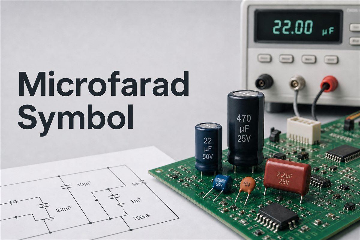
Microfarad Symbol Meaning: What Does µF Represent?
The correct SI-style microfarad symbol is µF: the prefix µ means micro, and F means farad. Because micro equals 10−6, a 1 µF capacitor has a capacitance of 0.000001 F. The prefix and unit are written together without a space.
Capacitance describes how much electric charge a capacitor stores per volt. The farad is large for many practical circuits, so designers usually work with microfarads, nanofarads, or picofarads. Power-supply filtering, audio coupling, timing, energy storage, and bulk decoupling often use µF values, while high-frequency decoupling and RF networks may use nF or pF values.
| Unit | Symbol | Farad value | Relationship |
| Farad | F | 100 F | 1 F = 1,000,000 µF |
| Microfarad | µF or uF | 10−6 F | 1 µF = 1,000 nF |
| Nanofarad | nF | 10−9 F | 1 nF = 1,000 pF |
| Picofarad | pF | 10−12 F | 1 pF = 0.001 nF |
What Does µF Mean on a Capacitor?
µF on a capacitor states its nominal capacitance in microfarads. A marking of 22 µF means 22 millionths of a farad. It does not describe the voltage rating, tolerance, polarity, temperature range, or dielectric, so those specifications must be checked separately.
For example, “22 µF 50 V” identifies a nominal 22 µF capacitance and a 50 V rated voltage. It does not mean the capacitor should operate continuously at 50 V in every circuit. Derating, ripple current, ESR, temperature, service life, package size, and manufacturer data still affect selection.
Capacitors are passive devices; readers who need a wider component classification can review active and passive components. The µF value tells you how much capacitance is intended, while the circuit function determines whether the part is suitable.
What Is the Microfarad Symbol on a Multimeter?
The microfarad symbol on a multimeter is usually shown as µF, uF, or a capacitance function marked with a capacitor icon. The exact display and selector marking vary by meter, so confirm the capacitance mode in the instrument manual instead of assuming that every model uses the same symbol.
Before measuring, disconnect power, discharge the capacitor safely, and isolate at least one lead when the surrounding circuit could affect the reading. Select capacitance mode, connect the probes with the correct polarity when required, wait for the reading to settle, and compare the measured value with the component tolerance and test conditions. Do not use resistance or continuity mode as a substitute for an actual capacitance measurement.
Are µF, uF, mF, and MFD the Same?
µF and uF normally mean the same thing, but mF does not. The letter “u” is an ASCII substitute used when a keyboard, database, CAD system, or label cannot display µ. In modern SI notation, lowercase m means milli, so 1 mF equals 1,000 µF.
- µF: preferred microfarad symbol.
- uF: common plain-text replacement for µF.
- mF: millifarad in modern SI notation; 1 mF = 1,000 µF.
- MFD: an older abbreviation often used for microfarad on legacy equipment and service documents.
Do not automatically interpret an old “MF” or “MFD” marking with modern SI rules. Confirm the component type, expected circuit value, schematic, and service documentation. This matters especially when replacing old capacitors, because a factor-of-1,000 error can change timing, filtering, inrush current, or circuit operation.
Microfarad Symbol to Farad Conversion
For microfarad symbol to farad conversion, multiply the µF value by 0.000001. Therefore, 1 µF = 0.000001 F, 10 µF = 0.00001 F, and 100 µF = 0.0001 F. To convert farads to microfarads, multiply the farad value by 1,000,000.
Microfarad to Nanofarad Conversion
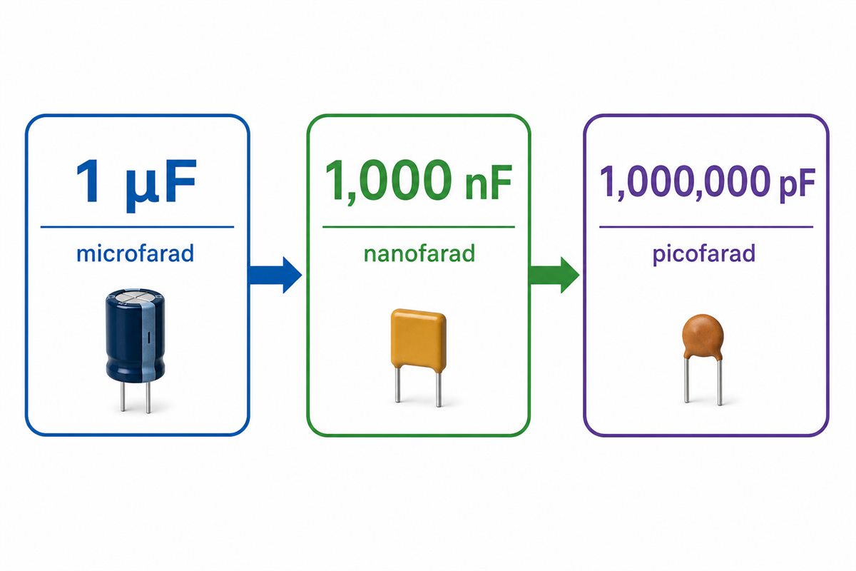
For microfarad to nanofarad conversion, multiply the µF value by 1,000. To convert nanofarads back to microfarads, divide by 1,000.
- 1 µF = 1,000 nF
- 0.1 µF = 100 nF
- 0.047 µF = 47 nF
- 0.01 µF = 10 nF
- 2.2 µF = 2,200 nF
A quick method is to move the decimal point three places to the right when converting µF to nF. For instance, 0.022 µF becomes 22 nF. Move it three places to the left for the reverse conversion.
Microfarad to Picofarad Conversion
For microfarad to picofarad conversion, multiply the µF value by 1,000,000. To convert pF to µF, divide by 1,000,000.
| µF | nF | pF |
| 1 | 1,000 | 1,000,000 |
| 0.47 | 470 | 470,000 |
| 0.1 | 100 | 100,000 |
| 0.047 | 47 | 47,000 |
| 0.01 | 10 | 10,000 |
| 0.001 | 1 | 1,000 |
Using the unit that produces a readable number reduces transcription mistakes. A schematic can show 0.0001 µF, but 100 pF is faster to read. Likewise, 0.1 µF and 100 nF describe the same capacitance; either can be correct if the project uses the notation consistently.
How to Read Capacitor Values and Marking Codes
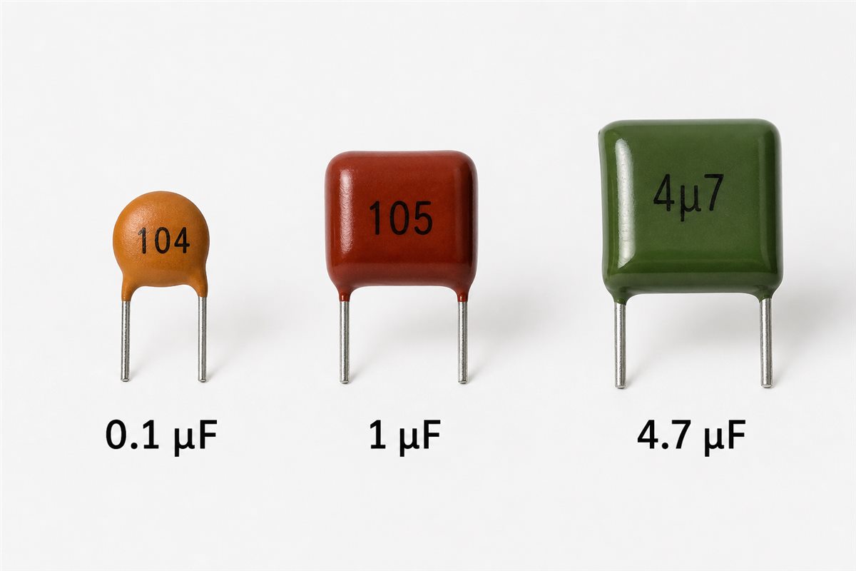
To learn how to read capacitor values, first identify whether the body prints a complete value or a compact code. Larger electrolytic capacitors often show a value such as 47 µF directly. Smaller ceramic and film parts may use three digits because there is not enough room for a full unit.
For a common three-digit capacitor code, the first two digits are significant figures and the third digit is the number of zeros in picofarads:
- 104: 10 followed by four zeros = 100,000 pF = 100 nF = 0.1 µF.
- 105: 10 followed by five zeros = 1,000,000 pF = 1,000 nF = 1 µF.
- 472: 47 followed by two zeros = 4,700 pF = 4.7 nF = 0.0047 µF.
Some markings use the prefix as a decimal point. For example, 4µ7 means 4.7 µF. A following letter may indicate tolerance, but marking systems vary by component family and standard. Always confirm the manufacturer datasheet before purchasing a replacement or releasing a BOM.
Is the Microfarad Symbol the Same as a Capacitor Symbol?
No. The microfarad symbol is a unit, while a capacitor symbol is a circuit-diagram graphic. µF tells you the scale of a capacitance value. Parallel plates, a curved plate, or a polarity mark show the capacitor as a component and may distinguish polarized from non-polarized types.
For the graphical forms used in schematics, see the BestPCBs capacitor symbol guide. When the circuit depends on polarity, also verify the difference between a polarized and non-polarized capacitor. A correct µF value does not protect a polarized capacitor installed backward.
How Does the µF Value Affect Capacitor Selection?
The µF rating is necessary but not sufficient for selecting a capacitor. Two parts with the same capacitance may behave differently because of voltage rating, dielectric, tolerance, ESR, ripple-current rating, leakage, temperature coefficient, package, polarity, aging, and frequency response.
- Decoupling: check impedance over the frequency range, not only the printed capacitance.
- Power filtering: review voltage, ripple current, ESR, temperature, and expected lifetime.
- Timing: consider tolerance, leakage, dielectric absorption, and bias effects.
- Signal coupling: verify the high-pass corner frequency and DC bias.
- Safety applications: use the required safety class and approvals rather than substituting an ordinary capacitor with the same µF value.
If a capacitor is connected across mains-related circuitry, consult the project safety requirements and the correct component class. The BestPCBs guide to a safety capacitor and testing explains why capacitance alone cannot establish suitability.
How to Prevent µF Errors in Schematics, BOMs, and PCB Assembly
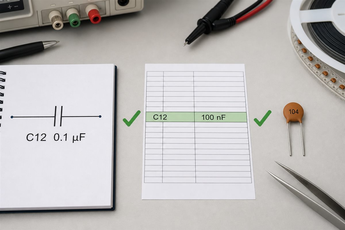
Prevent µF errors by normalizing capacitance values and checking every design document against the same approved part number. A schematic may show 0.1 µF, a BOM may show 100 nF, and a ceramic capacitor may carry the code 104. Those values agree, but an automated or manual check must recognize the conversion.
- Choose one preferred notation range for the project, such as pF below 1 nF, nF from 1 nF to below 1 µF, and µF from 1 µF upward.
- Keep the reference designator identical across schematic, BOM, pick-and-place data, assembly drawings, and inspection documents.
- Store capacitance as a numeric value plus a separate unit field where the data system allows it.
- Check for µF/uF equivalence and flag mF or MFD for manual review.
- Validate voltage, tolerance, dielectric, package, and polarity in addition to capacitance.
- During incoming inspection, compare reel labels and manufacturer part numbers with the approved BOM.
- For first-article inspection, confirm placement, orientation, package, and critical capacitance values.
How to Type the Microfarad Symbol on a Keyboard
When you need the microfarad symbol on a keyboard, the most reliable option is to enter or copy the Unicode character µ and add F. For a quick microfarad symbol copy and paste, use µF. If a CAD field, filename, codebase, database, or export format cannot preserve Unicode reliably, use uF and document that convention consistently.
Microfarad Symbol FAQ
What does the microfarad symbol look like?
The symbol is µF. The micro prefix means 10−6, while F is the symbol for farad. Therefore, 1 µF equals 0.000001 F.
What does the microfarad symbol look like on a multimeter?
Depending on the meter, capacitance may appear as µF, uF, or a capacitor icon. Confirm the selector position and display notation in the meter manual before testing.
Is uF the same as µF?
Yes. uF is the common ASCII spelling used when the µ character is unavailable. A value written as 10 uF is normally the same capacitance as 10 µF.
Is μF different from µF?
They may be encoded as different Unicode characters: Greek small letter mu and micro sign. In electronics documents they are commonly read as the same micro prefix. The project should use one consistent character to avoid search, export, or database mismatches.
How many nanofarads are in one microfarad?
One microfarad equals 1,000 nanofarads. Multiply a µF value by 1,000 to convert it to nF.
How many picofarads are in one microfarad?
One microfarad equals 1,000,000 picofarads. Multiply a µF value by 1,000,000 to convert it to pF.
What does 0.1 µF equal?
0.1 µF equals 100 nF or 100,000 pF. A capacitor using the common three-digit code may be marked 104.
What does 4µ7 mean on a capacitor?
4µ7 means 4.7 µF. The micro symbol takes the place of the decimal point in this compact marking format.
Does MFD mean microfarad?
MFD often means microfarad on older equipment, service manuals, and capacitor labels. Because modern SI notation uses mF for millifarad, confirm the intended value from the circuit and documentation before replacing the component.
Can I replace a capacitor with the same µF but a higher voltage rating?
A higher voltage rating may be acceptable in many circuits, but it is not the only requirement. Confirm component type, polarity, tolerance, ESR, ripple current, temperature, physical size, safety class, and manufacturer guidance.
Why do schematics use 100 nF instead of 0.1 µF?
Both values are equal. Designers often choose the unit that avoids leading zeros and makes the value easier to scan. Consistent notation also reduces transcription errors in BOM and assembly data.
Does a larger µF value always make a circuit better?
No. Changing capacitance can alter timing, filter response, inrush current, stability, energy storage, or startup behavior. Use the design value and verify any substitution through circuit analysis and component data.
How to type microfarad symbol?
Copy and paste µF when Unicode is supported. In plain-text CAD fields, code, filenames, or databases that cannot reliably store the symbol, use uF and document that convention.
Summary
The microfarad symbol is µF, while uF is its practical plain-text equivalent. Remember the core conversion: 1 µF = 1,000 nF = 1,000,000 pF. Keep mF separate, treat old MFD markings cautiously, and verify capacitance together with voltage, tolerance, dielectric, package, and polarity. Bookmark this µF conversion reference when checking schematics, BOMs, and capacitor body codes.
If you need PCB design review, component sourcing, prototype assembly, or production support, contact our engineering team at sales@bestpcbs.com with your schematic, BOM, PCB files, and assembly requirements.







