A metal backed PCB is used when heat affects product stability, component life, and soldering reliability. In high-power electronics, poor heat dissipation can cause LED lumen decay, MOSFET overheating, solder fatigue, unstable output, and early failure.
Compared with FR4 PCB, a metal-backed PCB spreads heat faster through its metal base, making it suitable for LED lighting, power modules, motor drivers, charging systems, and industrial controls. This guide explains materials, design factors, heat transfer, cost, lead times, quality control, and EBest Circuit’s custom metal backed PCB manufacturing support.
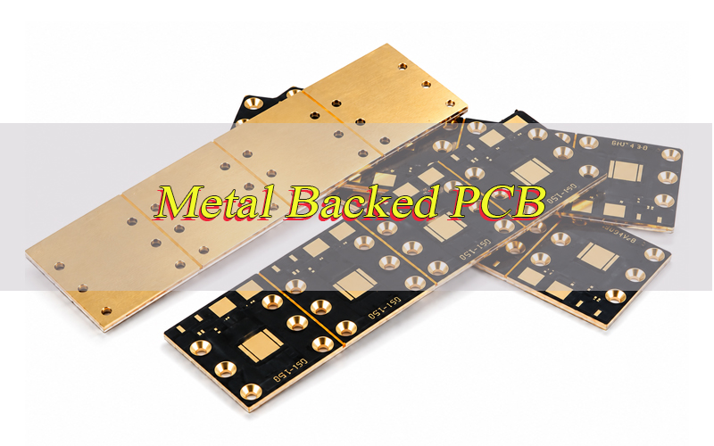
What Is a Metal Backed PCB?
A metal-backed PCB, also called as IMS (Insulated Metal Substrate) or MCPCB (Metal Core PCB) , is a printed circuit board built with a metal base, a thermal dielectric layer, and a copper circuit layer. The metal base usually uses aluminum or copper, while the dielectric layer provides electrical insulation and transfers heat into the metal structure.
The main purpose is thermal management in high-power or high-temperature electronics. Compared with a standard FR4 PCB, this structure spreads heat faster and reduces local hot spots. It is also called MCPCB, metal core PCB, insulated metal substrate, aluminum PCB, or copper base PCB depending on the material and design.
What Problems Can Metal Backed PCBs Solve in High-Power Electronics?
Metal-backed PCBs solve heat-related problems that standard boards may not handle well. When power devices, LEDs, MOSFETs, drivers, or regulators generate heat in a small area, the board can suffer temperature rise, solder fatigue, material stress, and unstable electrical performance.
The key problems include:
- Component overheating caused by poor heat spreading
- LED lumen decay caused by high junction temperature
- Solder joint cracks from repeated thermal cycling
- Power derating when devices cannot operate at full load
- Localized hot spots near high-current or high-power parts
- Unstable performance inside compact enclosures with limited airflow
For projects involving metal backed PCB suppliers for power electronics, the supplier should review both electrical load and thermal load before confirming the stackup. This type of project needs heat flow analysis, insulation safety, soldering reliability, and production consistency.
How Does a Metal-Backed PCB Improve Heat Dissipation?
A metal-backed PCB improves heat dissipation by creating a shorter heat path from the component to the metal base. Heat first moves from LEDs, MOSFETs, drivers, or power chips into the copper circuit layer, instead of staying around the component pad.
Then, the heat passes through the thermal dielectric layer. This layer transfers heat downward while keeping the circuit insulated from the metal substrate. A lower thermal resistance dielectric helps heat move faster, but insulation safety must still be controlled.
After heat reaches the aluminum or copper base, the metal spreads it across a larger area. This helps reduce local hot spots, lower temperature rise, and improve long-term product stability.
The final result depends on dielectric thickness, thermal conductivity, copper area, component placement, and contact with the housing or heat sink. A good MCPCB design connects the heat source, thermal path, and external cooling structure together.
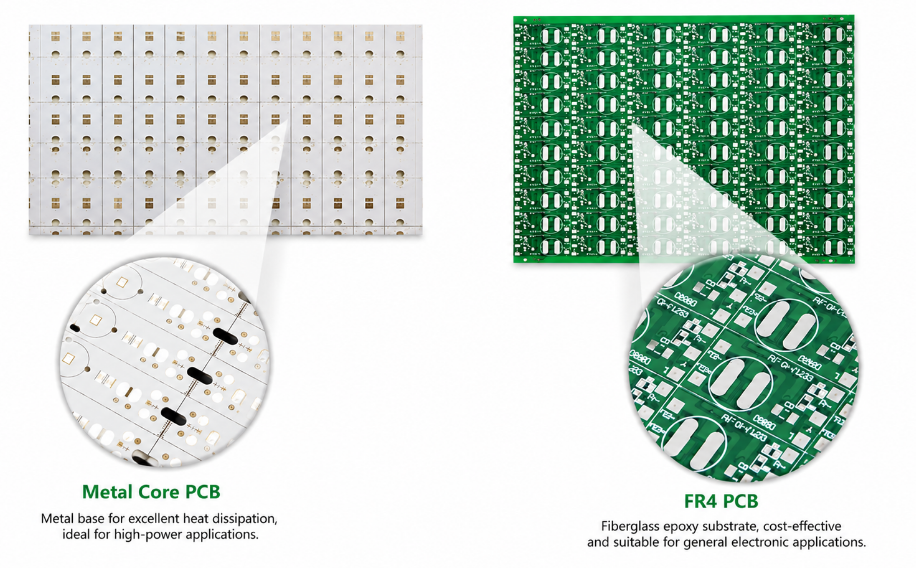
Metal Core PCB vs FR4 PCB: Which One Should You Choose?
Choose a metal backed PCB when heat dissipation, power density, and long-term thermal stability are the main design risks. Choose FR4 PCB when the product is low-power, cost-sensitive, or needs complex multilayer routing without heavy thermal load.
| Item | Metal-Backed PCB | FR4 PCB |
|---|---|---|
| Base Material | Aluminum, copper, or other metal substrate | Fiberglass epoxy laminate |
| Thermal Performance | Better heat spreading and lower hot spot risk | Lower heat transfer, relies on copper and airflow |
| Cost | Higher than standard FR4 PCB | Lower and widely available |
| Best Use | LED, power electronics, motor drivers, chargers | Consumer electronics, control boards, signal circuits |
| Mechanical Strength | Better rigidity and heat sink contact | Flexible for common PCB structures |
| Routing Flexibility | More limited for complex multilayer designs | Better for dense multilayer routing |
| Assembly Risk | Requires controlled soldering heat balance | Easier for standard SMT assembly |
| Design Focus | Thermal path, insulation, metal base contact | Signal routing, layer count, component density |
For high-power electronics, metal-backed PCB is usually the safer choice because the metal substrate moves heat away from power components faster than FR4 material. This helps reduce component overheating, LED lumen decay, solder fatigue, and thermal stress during long-term operation.
FR4 PCB is still the better option for many standard electronic products. If the board mainly carries control signals, low-current circuits, sensors, communication modules, or general SMT components, FR4 usually offers lower cost, easier fabrication, and better layout flexibility.
The final choice should be based on temperature rise, current load, component power, enclosure design, target cost, and assembly process. If heat is the main failure risk, choose a metal backed PCB. If routing complexity and cost are more important, FR4 PCB is usually more suitable.
Where Are Metal-Backed PCBs Commonly Used?
Metal-backed PCBs are used where heat, current, reliability, and compact space must be controlled together. These boards are common in products that run continuously or operate under high thermal load.
Common applications include:
- LED lighting for street lights, high-bay lights, automotive lights, and UV LED modules
- Power electronics such as converters, inverters, drivers, and power supplies
- Automotive electronics including lighting, battery modules, sensors, and control units
- Industrial equipment such as motor drives, automation controls, and power control boards
- Telecom systems including RF modules, base station power boards, and thermal control boards
- Charging products such as EV chargers, charging piles, and high-current power modules
- Medical and commercial devices where stable operation and heat control affect reliability
In these applications, the PCB is not only used for electrical connection. It also supports heat transfer, mechanical mounting, and long-term product reliability.
What Materials Are Used for IMS PCB Manufacturing?
Metal backed PCB manufacturing mainly uses copper foil, thermal dielectric material, and a metal substrate. Aluminum is the most common metal base because it balances cost, weight, machinability, and heat spreading. Copper base is selected when the project has higher thermal load or higher power density.
| Material | Feature | Common Use |
|---|---|---|
| Aluminum Base | Balanced cost and heat spreading | LED, power supply, control PCB |
| Copper Base | Higher thermal conductivity | High-power module, compact power PCB |
| Steel Base | Mechanical strength | Special structural PCB |
| Thermal Dielectric | Insulation and heat transfer | Metal core PCB structure |
| High-Tg Laminate | Better heat resistance | Soldering reliability and thermal cycling |
| Copper Foil | Circuit and current path | Power traces and pads |
Material selection should match thermal conductivity, insulation voltage, copper thickness, soldering temperature, mechanical strength, and operating environment. A low-cost material may pass a prototype but fail after long-term heat cycling, so material confirmation is an important early step.
What Design Factors Affect Metal-Backed PCB Thermal Performance?
Metal backed PCB thermal performance depends on the full heat path, not one material number. A high thermal conductivity value helps, but layout, copper distribution, dielectric thickness, component placement, and housing contact also decide the final temperature.
Key design factors include:
- Dielectric thickness: thinner dielectric can reduce thermal resistance, but insulation must remain safe.
- Thermal conductivity: higher conductivity helps heat move from copper to metal base faster.
- Copper thickness: thicker copper improves current capacity and lateral heat spreading.
- Component placement: high-power parts should connect to a short and direct heat path.
- Pad and copper area: larger copper areas help distribute heat before it enters the dielectric layer.
- Board flatness: better flatness improves contact with heat sinks or metal housings.
- Surface finish: finish choice should support solderability, storage life, and assembly reliability.
- Mechanical mounting: screws, thermal pads, and housing contact affect final heat transfer.
A good MCPCB design keeps the heat source, thermal path, and mechanical heat sink aligned. If these areas are separated, even a strong material may not deliver the expected thermal result.
How Do Integrated Thermal Vias Improve Metal-Backed PCB Heat Transfer?
Integrated thermal vias are most useful in metal backed PCB projects with double-sided structures, local heat transfer zones, or complex power layouts. They help connect hot copper areas to deeper copper layers, thermal pads, or special heat-spreading structures.
In some designs, thermal vias move heat away from power components before it concentrates around one local pad. However, the via design must consider hole filling, plating quality, insulation from the metal base, solder wicking, and assembly stability.
Experienced metal backed PCB suppliers should confirm whether integrated thermal vias truly improve the heat path before adding cost to the design. Poor via placement may increase cost without improving the actual thermal result.
What Special Requirements Matter for High-Tg Materials, Soldering Reliability, and Impedance Control?
Metal-backed PCB projects need extra control when the board works with high temperature, high current, thermal cycling, or mixed power-and-signal circuits. These factors affect material stability, solder joint strength, insulation safety, and signal performance.
- High-Tg material:
High-Tg material helps reduce warpage, delamination, softening, and dimensional change during lead-free soldering or long-term high-temperature operation. It is important for LED drivers, power modules, chargers, and industrial control boards. - Soldering reliability:
A metal base absorbs and spreads heat faster than FR4 PCB, so soldering heat balance must be controlled. Pad size, copper area, stencil opening, surface finish, and reflow profile should be reviewed to reduce poor wetting, cold solder joints, voids, and solder fatigue. - Insulation safety:
The dielectric layer must transfer heat and isolate the circuit from the metal base. For high-voltage or high-power products, insulation resistance and high-voltage testing help prevent leakage current, dielectric breakdown, and short risk. - Thermal cycling resistance:
Copper, dielectric material, solder joints, and metal base expand at different rates. Poor material or layout control can cause pad lifting, solder cracks, dielectric separation, and stress around power components. - Impedance control:
If the board includes control signals, RF areas, or communication lines, dielectric thickness, copper width, spacing, and stackup must be controlled. This helps reduce signal reflection, impedance drift, and unstable high-frequency performance. - Mechanical mounting:
Screw holes, board flatness, housing contact, and heat sink pressure affect heat transfer. Poor contact can reduce thermal performance even when the material itself has good conductivity.
What Metal-Backed PCB Solutions Can EBest Circuit Provide?
EBest Circuit provides custom metal backed PCB manufacturing for projects that require thermal control, stable fabrication, assembly support, and file review before production.
- Aluminum base PCB:
Suitable for LED lighting, power supplies, control boards, automotive lighting, industrial electronics, and commercial thermal products. It offers balanced heat spreading, stable production, and controlled cost. - Copper base PCB:
Suitable for compact high-power modules, power conversion products, and designs with higher heat density. It improves heat spreading but increases material cost, weight, and processing difficulty. - Single-sided MCPCB:
Suitable for LED modules, power drivers, and simple thermal boards where components are placed on one side and heat transfers directly to the metal base. - Double-sided MCPCB:
Used when the design needs more routing space, thermal vias, or special electrical connections. This structure requires tighter control of insulation, via quality, soldering balance, and flatness. - Custom material options:
Copper thickness, dielectric material, board thickness, metal base type, and surface finish can be reviewed according to current load, heat path, insulation requirement, and cost target. - DFM review:
Before production, EBest Circuit reviews Gerber files, drill files, stackup, copper distribution, hole design, insulation spacing, mounting holes, and panel design to reduce manufacturing risk. - PCBA support:
For metal-backed PCBA projects, we can support PCB fabrication, component sourcing coordination, SMT assembly, soldering control, testing, inspection, and packing.
Metal-Backed PCB Project Case: Solving Overheating in a Power Electronics Module
Project background:
A compact power electronics module used an FR4 PCB. During continuous load testing, the MOSFET area became too hot, and the output became unstable after long operation. The enclosure space was limited, so the product structure could not be changed significantly.
Requirements and difficulties:
- Move heat away from the MOSFET area faster without increasing board size.
- Reduce local hot spots caused by poor FR4 heat spreading.
- Keep the original enclosure and mounting structure as much as possible.
- Improve solder joint reliability under repeated heating and cooling.
- Prepare the design for repeat production, not only prototype testing.
Our solution:
EBest Circuit reviewed the Gerber files, copper layout, MOSFET placement, current path, screw hole position, housing contact area, and heat transfer route. The original copper area around the MOSFET pads was limited, so heat stayed near the power components.
We recommended a metal backed PCB with a shorter heat path from the MOSFET pads to the metal base. The copper area around the heat source was adjusted, the dielectric material was selected for both heat transfer and insulation, and the board structure was matched to the existing housing contact area.
We also reviewed pad connection, copper balance, and assembly heat absorption to reduce poor wetting, solder void risk, and thermal stress around high-power parts.
Output result:
After the pilot build, the heat path became clearer, housing contact improved, and the module ran more steadily during load testing. The project then moved into repeat production with inspection items for thermal structure, solderability, electrical function, insulation safety, and mechanical dimensions.
How Does EBest Circuit Evaluate Metal Backed PCB Quality Before Shipment?
EBest Circuit checks metal-backed boards before shipment through material confirmation, dimensional inspection, electrical testing, insulation review, visual inspection, and packing control.
- Material check:
Confirm metal base, dielectric layer, copper thickness, board thickness, and surface finish against the approved stackup. - Dimensional inspection:
Check outline, holes, slots, thickness, mounting areas, and key tolerances to avoid assembly mismatch with housings, heat sinks, screws, or frames. - Electrical test:
Use open and short testing to confirm circuit continuity before shipment. - Insulation test:
Use insulation resistance or high-voltage testing when required to verify separation between the circuit layer and metal base. - Thermal path review:
Check copper area, dielectric condition, exposed thermal zones, mounting surface, and metal base contact area to avoid blocked or weak heat paths. - Solder mask and finish check:
Inspect solder mask coverage, pad exposure, surface finish, oxidation, stains, scratches, and contamination that may affect solderability. - Hole and routing check:
Review vias, plated holes, non-plated holes, slots, routed edges, burrs, and hole position accuracy. - Flatness and appearance check:
Check warpage, dents, scratches, wrong marking, exposed metal damage, and surface defects before packing. - Packing check:
Pack boards with separation, labels, moisture protection when needed, and transport protection to reduce damage during international shipment.
What Affects Metal Backed PCB Cost and Lead Times?
Metal backed PCB cost and lead times mainly depend on material, structure, copper thickness, dielectric performance, tolerance, surface finish, testing, quantity, and file completeness.
- Metal base material:
Aluminum base is usually more economical and faster to arrange. Copper base improves heat spreading but increases cost, weight, machining difficulty, and lead time. - Thermal dielectric:
Higher thermal conductivity or higher insulation voltage can improve performance, but special dielectric materials may cost more and require longer preparation. - Copper thickness:
Thicker copper improves current capacity and heat spreading, but it increases etching difficulty, line control requirements, and production cost. - Board structure:
Single-sided boards are faster and more cost-effective. Double-sided MCPCB, plated holes, thermal vias, or special structures add process steps and inspection time. - Mechanical complexity:
Special outlines, slots, countersunk holes, dense mounting holes, strict flatness, and tight tolerances increase routing and inspection workload. - Surface finish:
HASL, lead-free HASL, OSP, and ENIG have different cost and processing requirements. ENIG offers better flatness and storage stability but usually costs more. - Testing requirements:
Electrical testing is standard. Insulation testing, solderability checks, dimensional reports, or special reliability tests add cost and time. - Order quantity:
Prototype orders have higher unit cost because setup and process review are spread across fewer boards. Batch production can lower unit cost after process stability is confirmed. - File completeness:
Complete Gerber files, drill files, stackup, material requirements, copper thickness, surface finish, tolerance, quantity, and test requirements shorten quotation and production review. - Material availability:
Standard aluminum base materials are easier to schedule. Copper base, uncommon thickness, high thermal conductivity dielectric, or special surface finish may extend lead time.
Why Choose EBest Circuit as Your Metal Backed PCB Supplier?
Choose EBest Circuit when your project needs stable quality, custom support, fast response, and one-stop PCB and PCBA service. With over 20 years of PCB manufacturing experience, EBest Circuit helps reduce design risk, production delay, quality problems, and supplier communication cost. Here are reasons why choose EBest as your metal backed PCB supplier:
- One-stop service:
We support PCB design, prototype, mass production, component sourcing, and PCB assembly. This helps simplify the process from bare board fabrication to finished PCBA delivery. - Custom thermal solutions:
We can review metal base material, dielectric layer, copper thickness, surface finish, insulation safety, and heat path design to match the product’s thermal requirements. - Prototype and batch production support:
Prototype builds help verify thermal performance, soldering reliability, and mechanical fit before mass production. Batch production can follow with clearer quality standards. - Certified quality control:
EBest Circuit supports projects with ISO 9001, IATF 16949, ISO 13485, AS9100D, UL, RoHS, REACH, and other quality and compliance requirements. - Flexible production capacity:
With monthly capacity of about 260,000 square feet, EBest Circuit can support small trial orders, repeat production, and custom PCB projects. - Fast delivery for urgent projects:
Expedited service is available for urgent boards, and some urgent PCB orders can be shipped within 24 hours when materials and files are ready. - Wide PCB technology coverage:
We support metal core PCB, FR4 PCB, multilayer PCB, ceramic PCB, flexible PCB, rigid-flex PCB, RF PCB, high-Tg PCB, heavy copper PCB, HDI PCB, high-speed PCB, and impedance control PCB.
A reliable metal backed PCB supplier should help control thermal performance, insulation safety, soldering reliability, production quality, delivery schedule, and final assembly risk. EBest Circuit supports these needs from file review to shipment.
FAQs About Metal Backed PCB
Q1: Can metal-backed PCBs be used in outdoor products?
A1: Yes, they can be used in outdoor lighting, charging equipment, industrial controls, and power modules. The board should match the working environment, including humidity, temperature change, UV exposure, vibration, and enclosure sealing. For outdoor use, surface finish, solder mask, coating, connector protection, and housing contact should be reviewed before production.
Q2: Does solder mask color affect thermal performance?
A2: Solder mask color has limited influence compared with dielectric material, copper area, and metal base contact. However, color can affect visual inspection, marking clarity, and product appearance. For LED lighting, white solder mask is often used for better light reflection, while black, green, or blue solder mask may be selected for product design or assembly needs.
Q3: Can components be assembled directly on a metal-backed PCB?
A3: Yes. SMT components, LEDs, power devices, connectors, and some through-hole parts can be assembled on metal-backed boards. The assembly process should control thermal mass, reflow profile, pad wetting, and fixture support, because the metal base absorbs heat differently from standard FR4 PCB during soldering.
Q4: Are metal-backed PCBs suitable for high-voltage applications?
A4: They can be used in high-voltage products if insulation design is properly controlled. The key is to confirm dielectric strength, clearance, creepage, hole spacing, and test voltage before manufacturing. For high-voltage LED drivers, chargers, and power modules, insulation testing between the circuit and metal base is especially important.
Q5: Can a metal-backed PCB be connected to a heat sink?
A5: Yes. In many products, the metal base is mounted directly to a heat sink, metal housing, or chassis. To improve contact, the design may use screws, thermal pads, thermal grease, flat mounting areas, or controlled pressure. Poor contact can reduce thermal transfer even when the PCB material has good heat conductivity.
Q6: Can metal backed PCBs be cut into special shapes?
A6: Yes, metal-backed boards can be routed, milled, drilled, slotted, or made with special outlines. However, complex shapes increase machining difficulty. Sharp corners, narrow bridges, dense holes, and tight edge tolerances should be reviewed because they may affect routing quality, burr control, flatness, and mechanical strength.
Q7: Do metal-backed PCBs need conformal coating?
A7: Conformal coating is optional and depends on the product environment. It may be useful for products exposed to humidity, dust, salt mist, chemical vapor, or outdoor conditions. Coating should not block thermal contact areas, connector contact points, screw grounding areas, or heat sink mounting surfaces unless the design specifically requires it.
Q8: Can metal-backed PCBs support through-hole components?
A8: Yes, but through-hole design needs extra review. Since the metal base is conductive, hole insulation, spacing, plating structure, and assembly clearance must be controlled. For some structures, non-plated holes or insulated holes may be required to prevent short risk, soldering difficulty, or mechanical interference.
Q9: What information helps verify thermal performance before production?
A9: Useful information includes power device locations, estimated power loss, target operating temperature, housing material, heat sink structure, airflow condition, mounting method, and test environment. These details help confirm whether the selected board structure can support real heat transfer, not only theoretical material data.
Q10: Can metal core PCBs be used with adhesive thermal pads?
A10: Yes, thermal pads are often used between the board and housing or heat sink. The pad should match thermal conductivity, thickness, compression force, insulation requirement, and operating temperature. A pad that is too thick or poorly compressed can increase thermal resistance and reduce heat transfer.
Q11: What packaging is suitable for metal-backed PCB shipment?
A11: Packaging should protect the board from scratches, oxidation, moisture, bending, and edge damage. Metal-backed boards are usually packed with separation layers, vacuum or moisture-proof bags when needed, labels, and strong outer cartons. For international shipment, edge protection and surface protection are important.
Q12: Can EBest Circuit support both bare metal-backed PCB and assembled PCBA?
A12: Yes. EBest Circuit supports PCB design, prototype, mass production, component sourcing, PCB assembly, inspection, and shipment. This helps reduce handover issues between fabrication and assembly, especially for products that need thermal control, soldering reliability, component matching, and final PCBA testing.
Conclusion
A metal backed PCB is a practical solution for products where heat affects stability, component life, soldering reliability, and long-term performance. The right board should match the actual power load, heat path, insulation requirement, material structure, assembly process, and final enclosure design.
For custom projects, the safest approach is to review the files before production and confirm the metal base, dielectric layer, copper thickness, surface finish, mounting method, and testing requirements. This helps avoid overheating, weak insulation, poor soldering, delayed delivery, and unnecessary cost changes.
EBest Circuit provides custom metal backed PCB and PCBA manufacturing for global projects, including file review, prototype, mass production, component sourcing, assembly support, quality inspection, and shipment. Send your Gerber files, stackup, quantity, material requirements, and project details to sales@bestpcbs.com for a custom quote.