An IR sensor is an electronic device that detects infrared radiation or uses infrared light to sense an object, distance, motion, temperature, or coded signal. In a practical product, sensor performance depends on more than the emitter and receiver: optics, component selection, PCB layout, mechanical geometry, calibration, and assembly quality must work as one system.
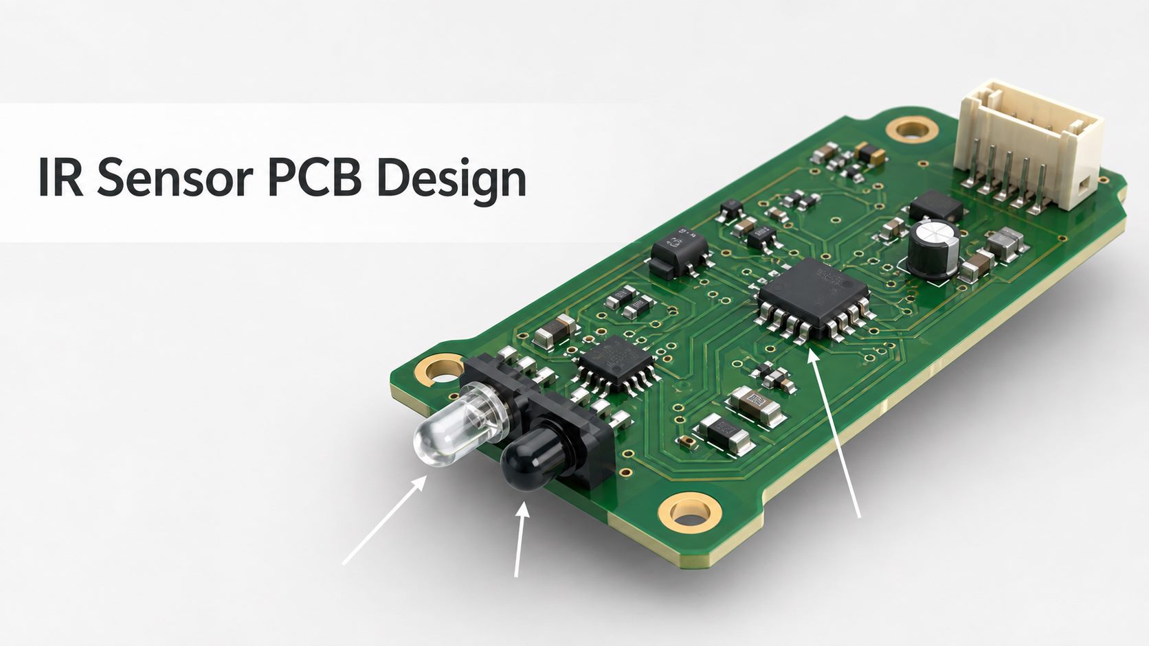
What Is an IR Sensor?
An IR sensor converts infrared energy into an electrical signal that a circuit can measure or interpret. “IR” means infrared, the portion of electromagnetic radiation beyond visible red light. Some sensors actively emit infrared light and measure what returns; others passively detect infrared energy already present in the scene.
The broad term covers several devices that should not be treated as interchangeable. A reflective proximity module, a remote-control receiver, a passive infrared motion detector, and a non-contact temperature sensor all use infrared energy, but their optics, signal chains, range limits, and PCB requirements are different.
Common IR Sensor Types and When to Use Them
The correct IR sensor type is determined by what must be detected and how the target interacts with infrared energy. The table below separates the most common categories before circuit or PCB decisions begin.
| IR sensor type | How it works | Typical use | Important design note |
| Reflective active IR sensor | An IR LED illuminates a target and a photodiode or phototransistor detects reflected light. | Object detection, line following, short-range proximity, counters | Target color, angle, ambient light, spacing, and optical barriers affect the result. |
| Break-beam or transmissive sensor | An emitter and receiver face each other; an object interrupts the beam. | Door detection, slot sensing, counting, safety interlocks | Mechanical alignment and contamination control are often more important than raw emitter power. |
| PIR motion sensor | A pyroelectric element detects changes in infrared energy across zones shaped by a lens. | Lighting, alarms, occupancy detection | It detects changing thermal patterns, not a stationary object at a precise distance. |
| IR remote receiver | A receiver module detects modulated infrared commands and rejects much steady ambient light. | Remote controls and coded communication | The carrier frequency and protocol must match the transmitter. |
| IR distance or time-of-flight sensor | Optical geometry, phase, or time-of-flight processing estimates distance. | Robotics, presence sensing, ranging | Follow the device maker’s optical window, field-of-view, layout, and calibration guidance. |
| IR temperature sensor | A thermopile or related detector measures emitted infrared energy to estimate temperature. | Non-contact thermometry and thermal monitoring | Field of view, emissivity, thermal isolation, and calibration drive accuracy. |
| IR flame sensor | A detector responds to infrared energy associated with flame signatures. | Flame monitoring and safety equipment | Safety functions require application-specific validation and suitable standards review. |
How Does an IR Sensor Work?
An active IR sensor works by emitting infrared light, receiving a portion of that light, conditioning the resulting electrical signal, and deciding whether the measured response represents a target. A passive sensor omits the emitter and detects changes in naturally emitted infrared energy instead.
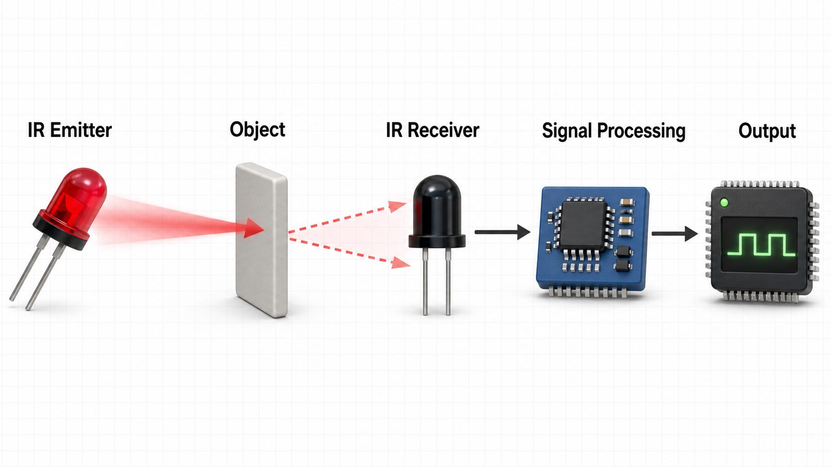
In a simple reflective circuit, the IR LED is current-limited and may be driven continuously or pulsed. The receiver produces a small current related to the returned light. A resistor, transimpedance amplifier, comparator, filter, or analog-to-digital converter turns that response into a useful voltage or digital state. Modulating the emitter and synchronously evaluating the receiver can improve rejection of constant ambient light, but the exact method should follow the selected component’s datasheet and application guidance.
What Components Are Used in an IR Sensor Module?
A typical IR sensor module combines optical, analog, digital, power, and connection components rather than relying on a sensor alone. The minimum architecture depends on whether the module provides a raw analog signal, an adjustable threshold, a digital output, or processed distance data.
- IR emitter: an infrared LED or other source selected for wavelength, drive current, beam angle, package, and pulse capability.
- IR receiver: a photodiode, phototransistor, integrated receiver, pyroelectric element, thermopile, or specialized detector.
- Analog front end: biasing, gain, filtering, and protection components that preserve a small sensor signal.
- Decision or processing circuit: a comparator, logic device, microcontroller, or sensor IC that produces a stable output.
- Power network: local decoupling, filtering, polarity protection, and voltage regulation where required.
- User interface and connection: headers, cable connectors, trim potentiometers, indicators, programming pads, and test points.
- Optical and mechanical parts: barriers, lenses, windows, apertures, housings, and fixtures that control the optical path.
IR Sensor PCB Layout Guidelines
A reliable IR sensor PCB layout protects a small optical signal from electrical noise while preserving the intended optical geometry. Start with the sensor manufacturer’s reference circuit and mechanical recommendations, then treat the optical path and analog front end as critical layout zones.
- Fix the optical geometry first. Place the emitter and receiver to match the required field of view, target distance, window, and housing. Do not finalize the PCB before checking the complete mechanical stack.
- Control optical crosstalk. Use physical separation, a dark barrier, suitable package orientation, or mechanical baffling so direct emitter light does not bypass the target and reach the receiver.
- Keep the receiver path short. Place the first gain or conditioning stage close to the detector and keep high-impedance nodes compact and clean.
- Separate noisy switching circuits. Keep clocks, DC-DC converters, fast LED drive edges, motors, and high-current return paths away from sensitive receiver traces.
- Place decoupling at the load. Locate bypass capacitors close to the sensor IC, comparator, amplifier, and controller power pins, following their datasheets.
- Plan grounding deliberately. Give the analog signal a controlled return path and prevent emitter current pulses from sharing a narrow return with the receiver front end.
- Add useful test access. Provide test points for supply rails, emitter drive, receiver output, threshold, and final output without creating long antenna-like stubs.
- Design for cleanliness. Flux residue, dust, fingerprints, and condensation can change leakage or optical transmission, especially around high-impedance nodes and optical windows.
What Determines IR Sensor Range and Accuracy?
IR sensor range is a system result, not a fixed property that can be inferred from the words “IR sensor.” Emitter power, receiver sensitivity, optics, target reflectivity, geometry, ambient radiation, signal processing, supply stability, and calibration all change the usable detection distance.
Reflective sensors can respond differently to a light matte target, a dark surface, polished metal, transparent material, or an angled object. Sunlight and incandescent sources can add infrared energy. A housing window may attenuate or scatter the desired wavelength. For these reasons, verify the design with representative targets, backgrounds, temperatures, lighting conditions, distances, and approach angles rather than testing only with a hand on a bench.
IR Sensor PCB Assembly and Inspection
Assembly quality matters because component position, contamination, solder joints, and mechanical fit can change the electrical or optical result. The optical components should be treated as alignment-sensitive parts when their height, tilt, or orientation affects the field of view.
- Confirm emitter and receiver polarity, orientation, height, tilt, and spacing against the drawing.
- Inspect fine-pitch sensor ICs and signal-conditioning components with AOI or suitable magnification.
- Use X-ray inspection when hidden joints, bottom-terminated packages, or other assembly risks justify it.
- Control cleaning so residue does not remain near high-impedance receiver nodes or optical surfaces.
- Check connectors, shields, optical barriers, lenses, windows, and housings after final assembly.
- Program and calibrate the module using controlled fixtures when the design stores thresholds or correction data.
For outsourced production, provide the PCB data, BOM with exact manufacturer part numbers, placement files, assembly drawings, polarity notes, optical/mechanical drawings, programming files, test limits, and approved alternatives. A generic “functional test” request is not enough; define the target, distance, lighting, motion, output, and pass/fail timing that the fixture must reproduce.
How to Test an IR Sensor PCB
An effective test plan separates electrical health from optical performance and then verifies the complete assembly under realistic conditions. This makes failures easier to diagnose and prevents a threshold adjustment from hiding a layout, assembly, or mechanical problem.
| Test stage | What to verify | Typical failure found |
| Power-off inspection | Polarity, orientation, solder quality, contamination, optical alignment | Reversed diode, tilted sensor, solder bridge, residue |
| Power integrity | Input current, rail voltage, ripple, startup behavior | Wrong value, short, unstable regulator, inadequate decoupling |
| Emitter check | Drive current or waveform using suitable instruments | Open LED, incorrect resistor, weak or missing pulse drive |
| Receiver signal | Dark level, illuminated level, gain, noise, saturation | Optical crosstalk, noise pickup, wrong bias, poor grounding |
| Functional threshold | Output state across defined targets and distances | Excess variation, incorrect threshold, firmware logic error |
| Environmental scenario | Representative ambient light, temperature, housing and target conditions | Sunlight interference, window loss, thermal drift, false triggering |
Common IR Sensor Problems and Design Fixes
Most IR sensor problems can be traced to optical crosstalk, ambient-light interference, electrical noise, target variation, contamination, or poor calibration. The fix should address the cause instead of merely increasing sensitivity.
- Always-on output: check direct emitter-to-receiver leakage, threshold polarity, receiver saturation, assembly residue, and firmware logic.
- Short or inconsistent range: verify emitter drive, target material, alignment, lens/window transmission, supply voltage, gain, and calibration.
- False triggers in sunlight: consider optical filtering, shielding, modulation, narrower field of view, better filtering, and revised thresholds.
- Unit-to-unit variation: review component tolerances, mechanical placement, optical barriers, calibration method, and fixture repeatability.
- Noisy analog reading: shorten sensitive traces, improve return paths and decoupling, separate switching currents, and verify amplifier stability.
- Works before enclosure assembly only: inspect the final window, reflections from internal surfaces, lens position, housing tolerances, and cable routing.
How to Select an IR Sensor and PCB Assembly Partner
Select the sensor by the detection task, then select manufacturing support by its ability to control the PCB, components, assembly, programming, inspection, and functional test as one traceable build. Buying a higher-cost sensor will not compensate for an uncontrolled optical design or an undefined production test.
Before requesting a quotation, define the target material, detection geometry, ambient conditions, response time, interface, supply, enclosure, calibration method, annual volume, and acceptance test. Ask the manufacturer how it will control component substitutions, polarity, optical alignment, cleanliness, programming, test fixtures, and failure analysis. Best Technology supports PCB fabrication, component sourcing, and PCB assembly from prototypes through production, allowing the sensor board and its test requirements to be reviewed together.
Frequently Asked Questions About IR Sensors
What is the full form of IR sensor?
IR sensor means infrared sensor. It is a device that detects infrared radiation or uses emitted infrared light to sense an object, signal, motion, distance, or temperature.
Is an IR sensor the same as a PIR sensor?
No. PIR is one type of infrared sensor. A passive infrared sensor detects changes in thermal radiation and normally has no IR emitter, while an active reflective IR sensor sends light and measures the return.
What is the typical pinout of an IR sensor module?
Many modules provide power, ground, and an analog or digital output, but there is no universal pinout. Some add enable, communication, threshold, or interrupt pins. Always use the exact module datasheet.
How far can an IR sensor detect?
The range varies from millimeters to many meters depending on sensor type, optics, target, emitter drive, receiver sensitivity, environment, and processing. Validate the selected part in the final mechanical design.
Can an IR sensor work in sunlight?
It can, but sunlight contains infrared energy that may reduce margin or cause saturation. Optical filters, modulation, shielding, controlled fields of view, signal filtering, and realistic outdoor testing can improve performance.
Why do black objects reduce reflective IR sensor range?
Many dark surfaces return less infrared energy to the receiver, although behavior depends on the material and wavelength. Test the actual target rather than assuming visible color alone predicts infrared reflectivity.
What is a TCRT5000 IR sensor?
The TCRT5000 is a reflective optical sensor family with an infrared emitter and phototransistor arranged in one package. Its exact electrical, optical, distance, and mechanical limits should be taken from the current Vishay datasheet.
Can I connect an IR sensor directly to an Arduino?
A compatible module may connect directly when its supply and output levels match the Arduino board. A raw photodiode or phototransistor usually needs biasing and signal conditioning. Check voltage, current, output type, and pinout first.
What affects IR sensor price?
Price depends on detector technology, optics, range, integrated processing, interface, package, environmental rating, calibration, traceability, order volume, and lifecycle status. Total module cost also includes the PCB, assembly, test, enclosure, and programming.
How should an IR sensor datasheet be reviewed?
Check wavelength, field of view or beam angle, drive limits, receiver response, supply, output interface, timing, ambient-light behavior, temperature range, package, reflow limits, optical window guidance, and application notes.
How can optical crosstalk be reduced on an IR sensor PCB?
Separate the emitter and receiver, add an opaque barrier or baffle, control package orientation, reduce reflective internal surfaces, and verify the enclosure. Modulation can reject ambient light but does not remove direct optical leakage.
What files are needed for IR sensor PCB assembly?
Provide Gerber or ODB++ data, drill files, BOM, placement data, drawings, approved substitutions, programming files, test requirements, optical/mechanical constraints, and calibration instructions. Include the final housing interface when alignment affects performance.
Final Design Checklist
A successful IR sensor design begins with the sensing task, not with a generic module. Confirm the sensor category, optical geometry, signal chain, PCB noise control, mechanical alignment, representative test targets, and production calibration before release.
If you’re sourcing reliable PCB/PCBA manufacturing for an IR sensor module, including OEM, ODM, prototyping, mass production, or custom engineering solutions, reach out to our engineering team for technical support and a quote at sales@bestpcbs.com.