Is IoT access control PCB quality affecting the reliability of your smart entry system? In smart locks, RFID terminals, biometric access devices, and networked door controllers, the PCB directly controls signal input, lock output, power stability, and communication performance.
A reliable smart access control PCB helps reduce access failure, unstable unlocking, connection drops, and production risk. For smart entry projects, the right PCB manufacturing partner should support fabrication, assembly, component sourcing, DFM review, and functional testing.
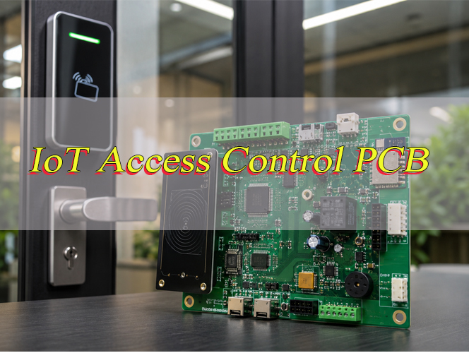
What Is an IoT Access Control PCB?
An IoT access control PCB is the main circuit board used in smart entry systems. It connects identity verification, door lock control, sensor feedback, power management, and network communication.
It is commonly used in:
- Smart door controllers
- RFID access control PCB systems
- Biometric access control PCB terminals
- PoE access control PCB systems
- Wireless smart lock PCB products
- Industrial access control equipment
Unlike a basic access control board, a networked access control PCB supports connected functions such as remote monitoring, access logs, device status reporting, and system integration.
How Does an IoT Access Control PCB Work in Smart Entry Systems?
An IoT access control PCB receives an access signal, verifies permission, drives the lock, checks door status, and sends data to the management system.
Basic working flow:
- The user presents a card, fingerprint, PIN, QR code, or mobile credential.
- The reader module sends the signal to the PCB.
- The MCU processes the access rule.
- The board controls the relay, MOSFET, or lock driver circuit.
- The door sensor reports open or closed status.
- The system records and uploads the access event.
The door access control PCB must respond quickly and remain stable during lock activation, network communication, and repeated daily operation.
What Components Are Used in an IoT Access Control PCB?
An IoT access control PCB usually includes control, power, communication, protection, and interface components.
| Component | Function | Focus |
|---|---|---|
| MCU / Processor | Main control logic | Memory, GPIO, security |
| Power IC | Voltage conversion | Efficiency, heat, ripple |
| Relay / MOSFET | Lock control | Load current, protection |
| Ethernet / Wi-Fi Module | Network connection | Signal stability |
| RFID / Biometric Interface | Identity input | Module compatibility |
| Memory | Access logs | Data retention |
| TVS / ESD Parts | Port protection | Surge resistance |
| Terminal Block | External wiring | Strength, current rating |
| Sensor Input Circuit | Door status | Filtering, protection |
The most critical parts are power circuits, lock drivers, connectors, communication modules, and protection components. These parts directly affect field reliability.
Which Communication Interfaces Are Common in IoT Access Control PCB?
Common interfaces include Ethernet, PoE, RS485, Wiegand, UART, Wi-Fi, Bluetooth, and CAN. The right choice depends on distance, installation environment, system structure, and communication stability requirements.
| Interface | Application | Focus |
|---|---|---|
| Ethernet | Networked access controller | Impedance, ESD |
| PoE | Power and data cable | Isolation, heat |
| RS485 | Long-distance wiring | Noise control |
| Wiegand | Card reader connection | Timing stability |
| UART | Module communication | Voltage matching |
| Wi-Fi | Wireless access device | RF layout |
| Bluetooth | Mobile credential | Low power |
| CAN | Industrial system | Bus protection |
For commercial and industrial systems, Ethernet, PoE, and RS485 are common. For compact smart locks, Wi-Fi, Bluetooth, and UART are often used.
What Should Be Checked Before IoT Access Control PCB Assembly?
Before IoT Access Control PCB assembly, the production files, components, soldering risks, programming steps, and testing requirements should be checked clearly. This helps reduce assembly mistakes and improves the stability of access control PCB production.
Key points to confirm before assembly include:
- Gerber and PCB fabrication files
Gerber files, drill files, copper layers, solder mask, silkscreen, board outline, and panel requirements should be complete. Clear files help avoid wrong board size, missing openings, incorrect holes, or production delays. - BOM accuracy
The BOM should include correct part numbers, values, package types, quantities, polarity, and approved alternatives. Key components such as MCU, relays, PoE ICs, Ethernet transformers, connectors, TVS diodes, and power ICs should be reviewed carefully. - Pick-and-place file
The pick-and-place file should match the PCB layout and BOM. Component coordinates, rotation, side placement, and reference designators should be correct before SMT assembly starts. - Connector and terminal block direction
Access control boards often use field wiring. Terminal blocks, Ethernet ports, pin headers, relays, and lock output connectors should face the correct direction for enclosure installation and cable connection. - Polarity and orientation checking
Diodes, electrolytic capacitors, ICs, LEDs, relays, connectors, and modules must have correct polarity or orientation. Wrong orientation may cause power failure, communication failure, or board damage. - SMT and through-hole process planning
Most access control PCB projects include both SMD parts and through-hole components. The assembly process should confirm reflow soldering, wave soldering, manual soldering, fixture support, and post-solder inspection requirements. - PoE and communication module assembly
If the board includes PoE, Ethernet, RS485, RFID, Wi-Fi, Bluetooth, or Wiegand interfaces, the related components should be checked for package compatibility, soldering quality, and interface protection. - Relay and lock output circuit checking
Relay, MOSFET, flyback diode, fuse, TVS diode, and lock output terminal should match the required load. This is important because lock circuits often handle current peaks during switching. - Programming and firmware requirements
If the board requires firmware, the programming file, programming port, verification method, and label requirement should be confirmed before assembly. This helps avoid shipping boards with incomplete or wrong firmware. - Functional test procedure
The test procedure should include power-on test, communication test, reader input test, relay output test, lock load simulation, sensor input test, and final visual inspection. Functional testing is especially important for access control PCBA because visual inspection cannot confirm real system performance. - Conformal coating or special process requirements
If the board is used in outdoor, humid, dusty, or industrial environments, coating requirements should be confirmed before assembly. Connectors, test points, switches, and programming areas should be masked if coating is required. - Packaging and labeling requirements
Finished boards should be packed to protect connectors, relays, terminals, and exposed solder joints. Labels, batch numbers, firmware version, and inspection records can also be confirmed if traceability is required.
A complete pre-assembly check helps improve IoT Access Control PCB assembly consistency. It also helps EBest detect file problems, component risks, soldering risks, and testing gaps before production.
How to Improve Security and Reliability in IoT Access Control PCB?
To improve security and reliability, an IoT access control PCB should protect both the electronic circuit and the access control function. The board must keep stable operation during power fluctuation, repeated lock switching, long cable connection, and external interference.
Practical methods include:
- Protect access data and device identity
For connected access control systems, the board may store user data, device ID, access logs, or communication keys. Secure MCU, protected memory, or secure element options can be used when the project requires higher data protection. - Control firmware access
Debug ports and programming interfaces should not be exposed without control. Production programming points can be reserved, but access should be managed through layout position, enclosure protection, firmware lock settings, or controlled programming process. - Use stable communication protection
Ethernet, RS485, Wiegand, UART, Wi-Fi, and Bluetooth circuits should be protected against noise and abnormal voltage. Wired ports should place TVS diodes and filters close to connectors. Ethernet and PoE layouts should also follow proper impedance and isolation requirements. - Add tamper detection circuits
For higher-security door systems, the PCB can reserve tamper switch inputs, enclosure open detection, forced-door detection, and abnormal door status signals. These inputs help the system identify unauthorized opening or installation damage. - Define safe lock status during failure
The board should define what happens during power loss, MCU reset, firmware update, communication failure, or abnormal voltage. The lock output should not enter an uncontrolled state. This point is very important for smart entry reliability. - Prevent system reset during lock activation
Lock activation often causes voltage drop or electrical noise. To reduce reset risk, separate lock power from logic power, increase local capacitance, use proper grounding, and protect relay or MOSFET output circuits. - Use proper relay and MOSFET protection
Electric locks and relay coils are inductive loads. They can create voltage spikes when switching. Flyback diodes, TVS diodes, snubber circuits, suitable relay ratings, and enough trace width help protect the output circuit. - Strengthen ESD and surge protection
Access control devices are connected to long cables and external modules. Static discharge or surge can enter through reader lines, lock cables, power input, Ethernet, RS485, and sensor inputs. Good protection design reduces field failure. - Improve connector and terminal reliability
Loose wiring is a common cause of access control failure. Use terminal blocks with suitable current rating, wire range, pitch, and mechanical strength. For vibration or industrial use, stronger connector locking or screw terminals may be required. - Separate outdoor reader circuits from main control circuits
In some systems, the reader is installed outside while the controller is placed inside a protected area. Separating exposed reader circuits from the main control board can reduce tampering risk and improve system security. - Use coating or surface protection when needed
Outdoor, humid, dusty, or industrial environments may require conformal coating. Coating helps protect the PCB from moisture, dust, corrosion, and contamination. However, connectors, switches, test points, and programming areas should be masked correctly before coating. - Verify reliability with real functional tests
The board should not only pass visual inspection. It should be tested with power-on checks, communication checks, reader input checks, relay output simulation, lock load testing, sensor input testing, and firmware programming verification. - Check long cable and real installation conditions
Some failures only appear with long cables, noisy environments, or repeated lock activation. Before larger production, the board should be tested under conditions close to the final installation environment. - Control assembly quality
Reliable hardware also depends on stable access control PCBA assembly. AOI, solder joint inspection, through-hole solder checking, component verification, connector inspection, and final function testing help reduce production variation. - Keep production records traceable
For repeated production, material batch, component batch, test results, and process records should be traceable. This helps maintain stable quality and makes problem analysis easier if an issue occurs later.
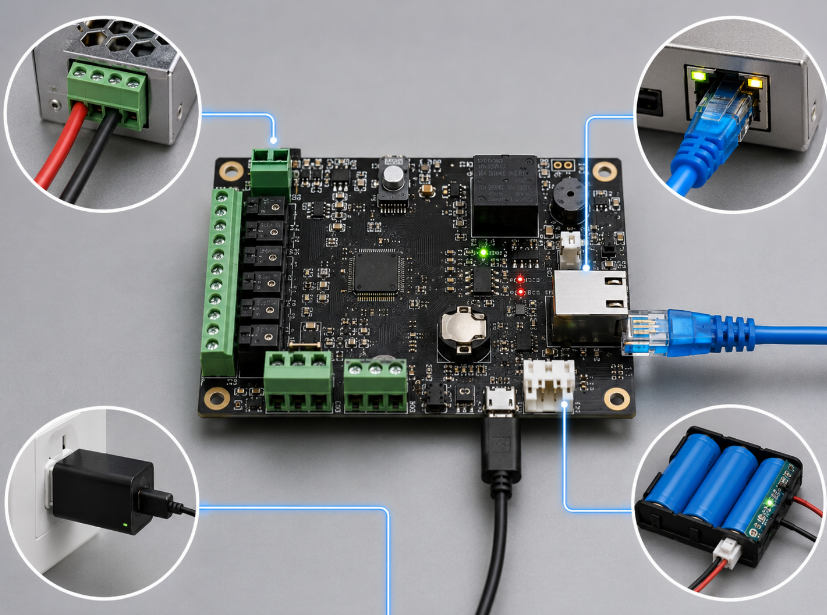
What Power Supply Options Are Used in IoT Access Control PCB?
Power supply design affects unlocking stability, communication performance, and product lifespan. Common options include DC input, PoE, battery backup, hybrid power, and bus power.
| Power Option | Suitable Use | Focus |
|---|---|---|
| DC Input | Standard controller | Input protection |
| PoE | Networked controller | Isolation, heat |
| Battery Backup | Smart lock | Low power |
| Hybrid Power | High-reliability system | Switching stability |
| Bus Power | Multi-device system | Voltage drop |
Lock activation can create current peaks. The PCB should include enough power margin, bulk capacitance, and proper load protection.
For wireless smart entry devices, low-power design is also important. Sleep mode, wake-up logic, and efficient voltage regulation help extend operating time.
How Does PoE Affect IoT Access Control PCB Performance?
PoE can improve an IoT access control PCB by combining power and data through one Ethernet cable. It is especially useful for smart entry systems installed in offices, buildings, campuses, hospitals, factories, and secured facilities where clean wiring and centralized power management are important.
Key effects of PoE include:
- Simpler wiring structure
PoE reduces separate power wiring because the Ethernet cable can carry both power and data. This makes installation cleaner and helps reduce wiring complexity in multi-door access control systems. - Better centralized power management
A PoE access control system can connect to a PoE switch or centralized power source. This makes device management easier and supports more organized power distribution across multiple entry points. - Stable network communication
Since PoE is based on Ethernet infrastructure, it supports stable data transmission for access logs, door status, remote control, and system monitoring. For commercial smart entry systems, this is often more reliable than unstable wireless communication. - Higher PCB power design requirements
A PoE door controller PCB must include a proper PD controller, Ethernet transformer, surge protection, and DC-DC power conversion circuit. If the power design is weak, the board may show overheating, unstable voltage, or random reboot issues. - More attention to thermal control
PoE circuits, DC-DC converters, regulators, and lock output circuits may generate heat during long operation. The PCB should reserve enough copper area, thermal vias, and spacing around power components. - Stronger surge and ESD protection
Ethernet cables may bring surge or electrostatic discharge into the board. Therefore, Ethernet ports and PoE input areas should include suitable TVS protection, isolation design, and grounding control. - Controlled impedance routing
Ethernet differential pairs should follow impedance requirements and avoid sharp routing, long stubs, and strong noise areas. Poor routing may cause packet loss, unstable communication, or failed network connection. - Clear separation between power and signal areas
PoE power conversion circuits should not interfere with MCU, RF, reader, or Ethernet signal lines. Layout separation helps reduce noise and improves system reliability. - Correct lock power budget
The board should calculate whether PoE power is enough for the MCU, reader module, communication module, sensors, and lock output. Some electric locks require higher current, so the total power budget must be confirmed before production. - Better suitability for smart building projects
PoE is a strong choice for networked door controllers and smart building access control systems. It supports neat wiring, remote management, and scalable deployment.
For IoT access control PCB manufacturing, PoE should be reviewed at schematic, layout, fabrication, assembly, and testing stages. EBest can help check PoE-related production risks, including transformer placement, thermal area, Ethernet routing, connector direction, and final functional testing.
What Are Common Problems in IoT Access Control PCB Projects?
Common IoT access control PCB problems usually come from unstable power, poor interface protection, weak lock output design, communication errors, connector issues, and incomplete testing. These problems may not appear during a short sample test, but they can appear after real installation.
Typical problems include:
- System reset during lock activation
Electric strikes, magnetic locks, solenoids, and motor locks can create current peaks. If the logic power and lock power are not separated well, the MCU may reset when the lock is triggered. - Unstable power supply
Voltage drop, weak DC-DC conversion, insufficient capacitance, or poor power trace width may cause random reboot, failed unlocking, or unstable communication. Power design should be checked under real load conditions. - Relay or MOSFET output failure
Lock loads are often inductive. Without proper flyback diode, TVS diode, snubber circuit, current margin, or trace width, relay contacts or MOSFETs may fail after repeated switching. - RFID or biometric module compatibility issues
Reader modules may use different signal levels, communication interfaces, or timing requirements. The PCB should confirm module interface, voltage, connector pinout, and firmware communication before production. - Ethernet or RS485 communication errors
Long cables, poor grounding, missing termination, weak ESD protection, or incorrect routing can cause unstable data transmission. Communication lines should be protected and routed away from high-current areas. - PoE overheating
PoE controller circuits and DC-DC converters can generate heat. If the board has poor copper area, compact component spacing, or limited enclosure ventilation, overheating may reduce reliability. - Weak ESD and surge protection
Door access systems connect to external readers, sensors, locks, exit buttons, and cables. These external lines can bring static discharge or surge into the PCB, damaging sensitive components. - Loose terminal block or connector failure
Access control boards often use field wiring. If terminal blocks do not match wire size, current rating, or installation force, loose contact may cause intermittent lock control or signal failure. - Poor mechanical fit
PCB size, mounting holes, connector height, cable direction, antenna position, and enclosure clearance must match the final product structure. A board can pass electrical testing but still cause installation problems if mechanical fit is ignored. - No proper test points
Without test points for power rails, programming, communication, relay output, and sensor input, production inspection becomes harder. This increases debugging time and may allow hidden defects to pass. - Firmware programming not verified
If programming steps and verification methods are not included in the assembly process, boards may ship with wrong firmware, incomplete configuration, or untested communication functions. - Incomplete functional testing
Visual inspection alone is not enough. Access control boards should be tested for power-on status, reader input, communication, relay output, lock load simulation, and sensor input response.
To reduce these problems, production should begin with a clear Gerber file, BOM, pick-and-place file, assembly drawing, firmware instruction, and test procedure. EBest can review these files before custom PCB assembly for access control systems to improve production stability.
How Does EBest Control Quality for IoT Access Control PCB Production?
EBest controls custom access control PCB production through file review, PCB fabrication inspection, component checking, assembly process control, and functional testing support. The goal is to reduce production risk and improve consistency from prototype to repeated production.
Main quality control steps include:
- Production file review
EBest checks Gerber files, drill files, BOM, pick-and-place files, assembly drawings, and special process notes before production. This helps find pad issues, missing files, wrong component orientation, unclear connector direction, and assembly risks. - DFM review before manufacturing
Pad size, trace spacing, hole size, solder mask clearance, panel design, copper balance, and component spacing are reviewed before fabrication. This improves IoT access control PCB manufacturing consistency. - PCB material and stack-up confirmation
Board material, layer structure, copper thickness, board thickness, solder mask, and surface finish are confirmed according to project requirements. This helps ensure the bare PCB matches electrical and mechanical needs. - Bare board electrical testing
PCB open and short tests help verify circuit continuity before assembly. This step reduces the risk of assembling components onto defective bare boards. - Component verification
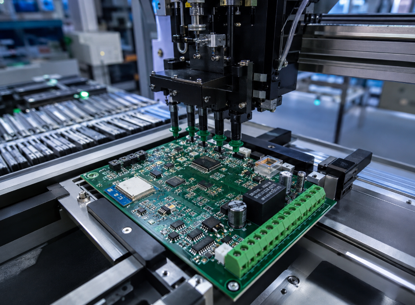
BOM parts are checked before assembly, especially MCU, relays, connectors, PoE ICs, Ethernet transformers, communication modules, protection components, and terminal blocks. Key components should match the approved specification. - SMT assembly process control
Solder paste printing, component placement, and reflow soldering are controlled during IoT Access Control PCB assembly. SPI and AOI can be used to check solder paste quality and placement accuracy. - Through-hole assembly inspection
Access control boards often include relays, terminal blocks, pin headers, switches, and connectors. These parts require stable through-hole soldering and strong mechanical inspection. - PoE and communication circuit attention
For PoE boards, EBest pays attention to Ethernet transformer placement, PoE input protection, DC-DC power section, heat area, and network interface assembly quality. - Connector and terminal block inspection
Since door access systems rely heavily on field wiring, connector alignment, solder strength, terminal block direction, and mechanical stability are carefully checked. - Power-on and functional testing support
Boards can be tested for power rails, current behavior, communication status, relay output, sensor input, and lock simulation based on project requirements. - Firmware programming and verification
If firmware programming is required, EBest can follow provided programming files and verification steps. This helps confirm that the board is not only assembled, but also functionally ready for use. - Final inspection and packaging
Final visual inspection checks solder joints, component position, board cleanliness, connector condition, label information, and packaging protection before shipment.
For access control PCB fabrication and assembly, EBest focuses on practical risk areas: power stability, lock output, communication circuits, PoE design, terminal blocks, and functional testing. This quality control flow helps improve delivery consistency and reduce avoidable production issues.

How to Choose a Reliable IoT Access Control PCB Manufacturer?
A reliable IoT access control PCB manufacturer should provide more than basic PCB fabrication. The right partner should support manufacturing, assembly, component sourcing, DFM review, test planning, and clear project communication.
Key selection points include:
- Experience with access control electronics
Access control boards include power circuits, lock drivers, reader interfaces, communication modules, relays, connectors, and protection components. A manufacturer familiar with these circuits can better understand production risks. - PCB fabrication and assembly capability
The supplier should support both IoT access control PCB manufacturing and access control PCBA service. This makes the project flow smoother from bare board production to assembled board delivery. - Support for SMT and through-hole assembly
Access control boards often include both small SMD components and larger through-hole parts such as relays, terminal blocks, connectors, and pin headers. Both assembly capabilities are important. - Ability to review design files before production
DFM review helps detect issues before manufacturing, such as small pads, tight spacing, unclear polarity, difficult soldering areas, weak panel design, and connector layout risks. - Understanding of PoE and communication circuits
If the board uses PoE, Ethernet, RS485, Wiegand, Wi-Fi, Bluetooth, or CAN, the manufacturer should understand related layout, protection, and assembly requirements. - Component sourcing support
A strong manufacturer can help check BOM availability, part alternatives, packaging type, lead time risk, and component consistency. This is important for stable production planning. - Functional testing support
The manufacturer should support power-on testing, communication testing, relay output testing, reader interface testing, and customized test steps when required. - Quality control transparency
Production quality should be supported by inspection steps such as electrical testing, SPI, AOI, X-ray when required, through-hole inspection, and final visual checking. - Clear communication during production
File questions, BOM substitutions, test requirements, packaging requirements, and production changes should be communicated clearly before action is taken. - Stable production scalability
The manufacturer should support prototype builds, small batches, and repeated production. This helps maintain product consistency after the project moves forward.
Before choosing a supplier, prepare Gerber files, BOM, pick-and-place file, assembly drawing, and testing requirements. Complete files allow the manufacturer to provide more accurate production review and avoid unnecessary delays.
Why Choose EBest as Your IoT Access Control PCB Manufacturer?
EBest provides IoT access control PCB fabrication and assembly for smart entry systems, RFID access devices, biometric terminals, PoE door controllers, smart locks, and industrial access control equipment.
EBest is suitable for access control PCB projects because:
- One-stop PCB manufacturing and assembly support
EBest supports PCB fabrication, SMT assembly, through-hole assembly, mixed assembly, component sourcing, and functional test support. This helps simplify project coordination. - Support for custom access control PCB requirements
EBest can support custom boards for RFID access control, biometric access control, PoE door controllers, smart locks, industrial entry devices, and networked smart entry systems. - DFM review before production
EBest can review production files before manufacturing to help identify risks related to pad design, component spacing, connector direction, panel layout, and assembly process. - Assembly support for key access control components
Access control boards often include relays, terminal blocks, PoE parts, Ethernet ports, connectors, protection components, MCU circuits, and communication modules. EBest can support SMT and through-hole assembly for these components. - Component sourcing support
EBest can help source components based on the BOM, including power ICs, relays, connectors, communication parts, protection devices, and passive components. - Production quality control
EBest supports process inspection such as bare board testing, component checking, SPI, AOI, through-hole inspection, power-on testing, communication testing, and final visual inspection. - Support for PoE and smart entry applications
For PoE access control boards, EBest can help review production risks around Ethernet layout, PoE power section, thermal area, connector placement, and assembly quality. - Functional test coordination
If test instructions are provided, EBest can support power, communication, reader interface, relay output, sensor input, and firmware verification testing. - Flexible project support
EBest supports prototype production, small-batch production, and repeated production for IoT access control PCB projects. - Professional project communication
EBest helps confirm files, components, assembly notes, test requirements, and delivery details before production. This reduces misunderstanding and improves project control.
Choosing EBest means working with a PCB partner that understands both manufacturing and access control application requirements. For smart entry systems, EBest helps turn PCB files into reliable assembled boards ready for project use.
FAQs About IoT Access Control PCB
Q1: Can an IoT access control PCB be customized for different smart entry systems?
A1: Yes. An access control controller PCB can be customized for RFID access terminals, biometric devices, smart locks, PoE door controllers, wireless entry systems, and industrial access equipment. The customization usually includes board size, connector position, communication interface, lock output circuit, power input, and sensor input design.
Q2: What files are required for IoT access control PCB production?
A2: The common files include Gerber files, drill files, BOM, pick-and-place file, assembly drawing, and testing instructions. If the board requires firmware programming, the programming file and verification steps should also be provided.
Q3: Can a smart access control PCB support PoE, Ethernet, RS485, and RFID interfaces at the same time?
A3: Yes. A smart access control PCB can support multiple interfaces, including PoE, Ethernet, RS485, Wiegand, UART, RFID, Wi-Fi, Bluetooth, and sensor inputs, if the circuit design and layout are planned correctly.
Q4: How can IoT access control PCB reliability be improved before mass production?
A4: Reliability can be improved through DFM review, component verification, proper protection design, power-on testing, communication testing, relay output simulation, and lock load testing.
It is also useful to check long cable operation, PoE heat performance, reader compatibility, sensor input response, and firmware programming verification before larger production.
Q5: What are the most common failure risks in access control PCB projects?
A5: Common risks include unstable power supply, relay output failure, PoE overheating, RS485 communication errors, weak ESD protection, loose terminal blocks, poor mechanical fit, and incomplete functional testing.
These problems can usually be reduced by confirming the power input, lock load, communication interface, connector type, protection circuit, and test procedure before production.
Q6: Can EBest support both prototype and repeated production for IoT access control PCB projects?
A6: Yes. EBest supports prototype production, PCB assembly, component sourcing, DFM review, and repeated production support.
Q7: Why should custom PCB assembly for access control systems include functional testing?
A7: Functional testing confirms that the assembled board can actually work in the access control system. Visual inspection alone cannot verify reader input, relay output, network communication, sensor response, firmware status, or lock control performance.
How Can You Start an IoT Access Control PCB Project with EBest?
To start an IoT access control PCB project with EBest, send your Gerber files, BOM, pick-and-place file, assembly drawing, and testing requirements. If your board includes PoE, Ethernet, RS485, RFID, biometric modules, relays, or lock output circuits, EBest can review the production details before manufacturing.
EBest provides IoT access control PCB manufacturing and assembly, component sourcing, DFM review, and functional test support for smart entry systems. For high-quality custom production and reliable project coordination, contact EBest at sales@bestpcbs.com and send your project files for quotation and technical review.