

Do you struggle with properly connecting or disconnecting an FPC cable without damaging the FPC cable or the device itself? If you work with electronics from consumer gadgets to industrial equipment understanding how to handle FPC cables correctly is essential to avoid costly repairs and ensure reliable performance.
This guide breaks down everything you need to know about FPC cables, from their definition and types to step-by-step instructions for connecting, disconnecting, soldering, and more. Whether you’re a beginner or an experienced technician, this guide will provide you with the expertise to work with FPC cables confidently.
What is a FPC Cable?
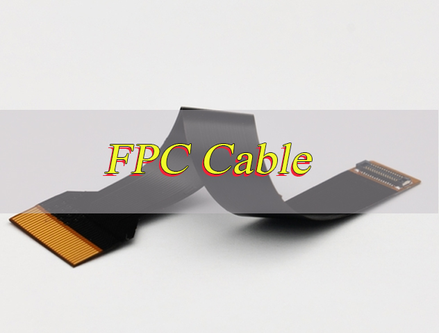
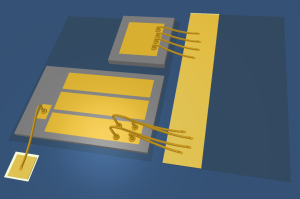
FPC cable full form is Flexible Printed Circuit Cable. As the name suggests, it is a flexible circuit assembly designed to transmit electrical signals between electronic components, offering a more versatile alternative to rigid circuit boards.
This flexible interconnect is a thin, flexible circuit board that uses conductive traces printed on a flexible substrate, typically polyimide or polyester. This substrate is what gives the flexible circuit its flexibility, allowing it to adapt to tight spaces and complex device layouts that rigid boards cannot accommodate.
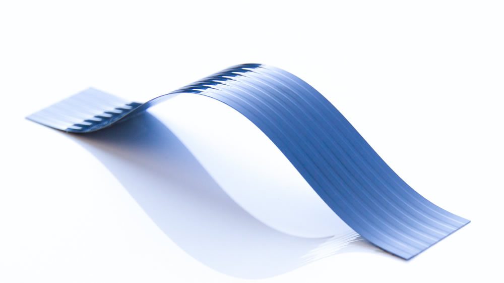
Unlike rigid circuit boards, these flexible assemblies can bend, twist, and fold without breaking. This key feature makes them ideal for devices that require movement or have limited internal space, such as smartphones, tablets, and wearables. Their flexible design alsoreduces overall weight and size, which is crucial for modern compact electronics.
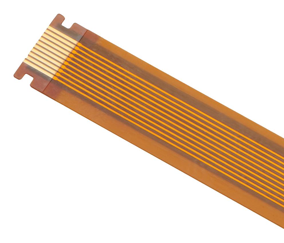
Every flexible printed circuit consists ofthree core components: a flexible base material (substrate), conductive copper traces for signal transmission, and a protective cover layer. The cover layer shields the copper traces from physical damage, oxidation, and electromagnetic interference, ensuring the flexible interconnect delivers reliable performance over time.
What Are Types of FPC Cable?
Flexible printed circuits cables come in several types, each designed for specific applications based on their structure and functionality. Understanding these types helps you choose the right flexible interconnect for your project:
- Single Sided Flexible Circuit Cables: The most basic type, with conductive traces on one side of the flexible substrate. It is lightweight, cost effective, and commonly used in simple devices like remote controls and small sensors.
- Double Sided Flexible Circuit Cables: Features conductive traces on both sides of the substrate, connected by vias. This type offers more wiring options and is used in devices that require more complex connections, such as smartphones and cameras.
- Multilayer Flexible Circuit Cables: Has three or more layers of conductive traces, separated by insulating layers. It is ideal for high density, complex circuits in devices like laptops, medical equipment, and automotive electronics.
- Rigid Flex Flexible Circuit Cables: Combines flexible and rigid sections in one assembly. The rigid parts provide stability for components, while the flexible parts allow bending, making it perfect for devices with moving parts like foldable phones.
What is FPC Cable Used for?
Flexible printed circuit cables are integral to nearly every modern electronic device, thanks to their flexibility and compact design. Their primary use is to transmit electrical signals between components where rigid cables or circuit boards cannot fit. Common applications include:
- Consumer Electronics: Smartphones, tablets, laptops, smartwatches, cameras, and gaming consoles use these flexible interconnects to connect screens, cameras, batteries, and other internal components.
- Automotive Electronics: Flexible printed circuits are used in car infotainment systems, dashboards, sensors, and door locks, where they withstand vibration and temperature changes.
- Medical Equipment: Devices like heart monitors, ultrasound machines, and wearable medical devices rely on these flexible assemblies for their flexibility and biocompatibility.
- Industrial Equipment: Industrial sensors, robotics, and automation systems use flexible printed circuits to connect components in tight, moving spaces.
How to Connect FPC Cable?
Connecting a flexible printed circuit cable requires precision to avoid damaging the connector or the assembly itself. Follow these step by step instructions to ensure a secure, reliable connection:
1. Prepare the Workspace: Clean the area to remove dust, dirt, or debris that could interfere with the connection. Use a lint free cloth and isopropyl alcohol to wipe the FPC connector and the flexible circuit’s gold fingers (the exposed conductive ends). A clean connection ensures stable signal transmission and prevents contact issues later.
2. Identify the Connector Type: Most FPC connectors are ZIF (Zero Insertion Force) connectors, which have a small lever or tab that locks the flexible assembly in place. Locate this lever before proceeding. Non-ZIF connectors lack this lever and require gentle pressure to insert the flexible circuit, so knowing the type avoids unnecessary force.
3. Open the Connector: Gently lift the ZIF lever using a small tool like a spudger or tweezers. Do not force the lever; it should lift easily to a 90 degree angle. For non ZIF connectors, skip this step. Forcing the lever can break the connector, rendering it unusable and requiring replacement.
4. Align the Flexible Circuit: Match the gold fingers of the flexible printed circuit with the contacts inside the connector. The assembly’s notched edge (key) should align with the notch in the connector to ensure correct orientation. Never reverse the flexible circuit, as this can cause short circuits that damage the assembly and the device.
5. Insert the Assembly: Slide the flexible printed circuit into the connector until it sits flush against the back of the connector. Ensure all gold fingers are fully inserted and not bent or misaligned. Partial insertion will lead to poor signal quality or complete connection failure.
6. Lock the Connector: Gently press the ZIF lever back down until it clicks into place. This secures the flexible assembly and ensures proper electrical contact. For non ZIF connectors, press the flexible circuit firmly into the connector until it is seated. A secure lock prevents the flexible interconnect from coming loose due to vibration or movement.
7. Test the Connection: Power on the device to verify that the flexible printed circuit is transmitting signals correctly. If the device does not function, check the alignment and reinsert the assembly if needed. Testing immediately catches issues early, avoiding further damage from incorrect connections.
8. Avoid Static Electricity: Static can damage the sensitive traces of the flexible circuit. Ground yourself by touching a metal surface before handling the assembly, and avoid working in dry, carpeted areas that generate static. This simple step prevents costly static-related damage.
9. Handle the Assembly Gently: Never pull or twist the flexible printed circuit while inserting it. Hold the assembly by its body, not the gold fingers or thin traces, to avoid tearing or bending the conductive elements. Rough handling is a common cause of flexible circuit failure.
10. Check for Damage Before Insertion: Inspect the flexible printed circuit’s gold fingers for bending, tarnishing, or tears before connecting. If damage is present, replace the assembly to prevent connection issues or device damage. Using a damaged flexible circuit can lead to short circuits or intermittent signal problems.
11. Ensure Proper Assembly Tension: After inserting and locking the flexible printed circuit, check that there is no excessive tension on the assembly. Pulling the flexible circuit taut can strain the connector and traces over time, leading to premature failure. Leave a small amount of slack for flexibility.
How to Disconnect FPC Cable?
Disconnecting a flexible printed circuit cable incorrectly is a common cause of damage. Follow these steps to safely remove the assembly without harming the connector or the flexible circuit:
1. Power Off the Device: Always turn off the device and disconnect it from any power source before disconnecting the flexible printed circuit. This prevents short circuits that could damage the flexible assembly, connector, or internal device components. It also eliminates the risk of electric shock during the process.
2. Locate the ZIF Lever: If the connector is a ZIF type, find the small lever or tab that locks the flexible assembly in place. Use a small, non-conductive tool like a spudger or plastic tweezers to gently lift the lever to a 90-degree angle. Never use metal tools that could scratch or damage the connector pins, and do not force the lever as this can break the connector.
3. Check for Secondary Locks: Some FPC connectors have a secondary lock or clip in addition to the ZIF lever. Inspect the connector carefully for any additional locking mechanisms and release them gently before attempting to remove the flexible printed circuit. Forgetting this step can lead to torn traces or broken connectors.
4. Remove the Assembly Properly: Once the connector is unlocked, gently pull the flexible printed circuit straight out of the connector. Pull from the assembly’s body, not the exposed gold fingers, to avoid tearing the traces or peeling the cover layer. If the flexible circuit feels stuck, wiggle it slightly side to side while pulling gently never force it, as this can bend the connector pins.
5. Inspect the Assembly and Connector: After removal, check the flexible printed circuit’s gold fingers for damage such as bending, tarnishing, or tearing. Inspect the connector’s pins for bent or broken contacts. If either is damaged, the flexible assembly or connector may need replacement to ensure reliable performance.
6. Close the Connector: If you are not reinserting a flexible circuit immediately, gently press the ZIF lever back down to protect the connector’s pins from dust, debris, and physical damage. Dust buildup can interfere with future connections and cause signal issues.
7. Store the Flexible Circuit Safely: If the flexible printed circuit is not being reused immediately, store it in a clean, dry container away from sharp objects, heat, and moisture. Avoid bending or folding the assembly unnecessarily during storage to prevent trace damage.
8. Avoid Static Damage: Static electricity can damage the sensitive traces of the flexible printed circuit. Ground yourself by touching a metal surface before handling the assembly, and avoid working in carpeted areas or dry environments that generate static. Consider using an anti-static mat if available.
How to Make FPC Cable?
Making a flexible printed circuit requires specialized equipment and materials, as it involves precise printing and assembly. Here is a simplified overview of the manufacturing process, suitable for understanding how these flexible interconnects are produced:
1. Prepare the Substrate: Start with a flexible substrate, usually polyimide, which is cut to the desired size. The substrate is cleaned thoroughly to remove any contaminants that could affect the adhesion and conductivity of the copper traces. Use a lint-free cloth and isopropyl alcohol for cleaning to ensure no residue remains.
2. Apply Copper Layer: A thin layer of copper is laminated onto the substrate using controlled heat and pressure. The copper foil, typically supplied in rolls, is bonded tightly to the substrate to form the base for conductive traces. Common copper thickness ranges from 12μm to 35μm based on the flexible circuit’s current requirements.
3. Apply Photoresist Layer: A photosensitive photoresist layer is evenly coated onto the copper surface. This layer hardens when exposed to UV light, allowing the circuit pattern to be transferred onto the copper.
4. Print the Circuit Pattern: The desired circuit pattern is printed onto the photoresist using a laser or UV light. This process masks the areas of copper that will remain as conductive traces, while the unexposed photoresist remains soft and removable.
5. Develop the Photoresist: The substrate is dipped into a developing solution to remove the unexposed, soft photoresist. This leaves only the masked areas (the circuit pattern) covered in hardened photoresist, protecting the copper underneath.
6. Etch the Copper: The substrate is immersed in an etching solution that removes the unprotected copper (areas without photoresist). This step creates the precise conductive traces of the flexible printed circuit. The etching time is controlled to avoid over-etching, which can damage the traces.
7. Remove the Photoresist: After etching, the hardened photoresist is stripped away using a stripping solution, leaving the clean, exposed copper traces on the substrate.
8. Apply Cover Layer: A protective cover layer, made of polyimide or insulating material, is applied over the copper traces. This layer shields the traces from physical damage, oxidation and electromagnetic interference. Holes are punched to expose the gold fingers for connection.
9. Add Reinforcements (If Needed): Reinforcement layers, such as FR4 or steel sheets, are applied to areas where the flexible printed circuit connects to connectors. These reinforcements add stability and prevent tearing during assembly and use.
10. Finish and Test: The flexible printed circuit is cut to the final size using precision tools. The gold fingers are plated with gold to improve conductivity and corrosion resistance. The assembly is then tested for continuity, signal integrity and performance to ensure it meets specifications.
How to Solder FPC Cable?
Soldering a flexible printed circuit cable requires precision to avoid overheating the assembly or damaging the traces. Follow these steps for a successful solder job:
1. Gather Tools and Materials: You will need a soldering iron with a fine tip (0.5mm or smaller), solder (preferably 0.3mm to 0.5mm diameter, lead-free for compliance), rosin-core flux (avoid acid flux which damages flexible circuit traces), anti-static tweezers, a heat sink, isopropyl alcohol (70%-90% concentration), and a lint-free cloth. Avoid using large-tip soldering irons, as they deliver excessive heat to the delicate flexible substrate.
2. Pre-Bake the Flexible Circuit (If Needed): Flexible printed circuits are prone to absorbing moisture, which can cause bubbling or delamination during soldering. If the assembly has been stored in a humid environment, pre-bake it at 80-100℃ for 4-8 hours to remove moisture before soldering this prevents irreversible damage to the substrate and traces.
3. Prepare the Assembly and Connector: Clean the flexible printed circuit’s gold fingers and the connector’s pads with isopropyl alcohol and a lint-free cloth to remove dirt, oxidation, and oil. Apply a small amount of rosin flux to the gold fingers and pads; flux improves solder flow, prevents oxidation during heating, and ensures a strong, reliable joint.
4. Secure the Assembly and Add Heat Protection: Use anti-static tweezers to hold the flexible printed circuit in place, aligning the gold fingers perfectly with the connector’s pads. Attach a heat sink to the flexible assembly near the soldering area to divert excess heat away from the flexible substrate this prevents the substrate from melting, warping, or delaminating.
5. Set the Correct Soldering Temperature: Heat the soldering iron to 330 ± 20 °C for lead-free solder. For flexible printed circuits with thin traces (12-18μm copper), lower the temperature to 310-320℃ to reduce heat exposure. Avoid temperatures above 350℃, as they will quickly damage the flexible substrate and traces.
6. Solder the Connections Properly: Touch the soldering iron tip to the gold finger and connector pad simultaneously to heat both surfaces evenly. Once heated (after 1-2 seconds), feed a small amount of solder into the joint enough to cover the pad and gold finger without creating bridges. Each joint should be soldered in 3-4 seconds maximum; prolonged heat contact will damage the flexible assembly.
7. Inspect the Solder Joints: After soldering, examine each joint with a magnifying glass. Good joints are smooth, shiny, and evenly coated (no gaps between the solder and pad). Avoid cold joints (dull, grainy solder) or solder bridges (solder connecting adjacent traces), as both cause poor conductivity or short circuits.
8. Clean the Area Post-Soldering: Use a lint-free cloth dipped in isopropyl alcohol to wipe away excess flux and solder residue from the flexible printed circuit and connector. Residue buildup can attract dust, cause corrosion over time, or interfere with signal transmission.
9. Test for Continuity: Use a multimeter to check continuity between the flexible printed circuit’s traces and the connector pads. This confirms that the solder joints are secure and there are no breaks or short circuits. If continuity is missing, reheat the joint and add a small amount of solder to fix the connection.
10. Handle the Assembly Gently After Soldering: Allow the flexible printed circuit and solder joints to cool completely (at least 5 minutes) before moving or handling the assembly. Hot solder joints are fragile and can crack if disturbed, and the flexible substrate remains vulnerable to damage until fully cooled.
11. Use a Rigid Carrier for Large Flexible Circuits: For longer or wider flexible printed circuits, secure the assembly to a rigid carrier (such as a small piece of FR4 or aluminum) with high-temperature tape before soldering. This prevents the flexible circuit from flexing during soldering, which can cause misalignment and poor solder joints.
12. Avoid Common Soldering Mistakes: Never use acid flux, as it corrodes flexible circuit traces and substrate. Do not apply excessive solder, as it creates bridges and adds unnecessary weight. Avoid touching the flexible substrate with the soldering iron, as direct heat will melt or damage the insulating layer.
How to Design a FPC Cable?
Designing a flexible printed circuit cable requires careful consideration of electrical, mechanical, and manufacturing requirements. Follow these key steps to design a functional, reliable flexible interconnect:
1. Define Requirements Clearly: Determine the flexible circuit’s core purpose including signal type (analog or digital), current rating, voltage, length and bending requirements (static or dynamic folding). Note the device’s space constraints and operating environment (temperature, humidity, vibration) to ensure the flexible assembly fits your device and performs reliably long-term. Dynamic bending scenarios like foldable phone hinges need more flexible designs than static applications like camera modules.
2. Choose Materials Wisely: Select a flexible substrate based on your application. Polyimide (PI) is ideal for high-temperature environments such as automotive and industrial equipment and dynamic bending while polyester (PET) works for cost-sensitive, static-flex applications. For copper foil use 12-18μm electrolytic copper for dynamic bending areas for better flexibility and 25-35μm rolled copper for static areas for higher current capacity. Choose a PI cover layer with acrylic adhesive to withstand SMT reflow temperatures up to 260℃ without peeling.
3. Design the Circuit Pattern for Reliability: Use PCB design software to create the circuit pattern ensuring trace width and spacing meet electrical needs. Traces should be wide enough to handle the required current with thicker traces for higher current and spaced to prevent crosstalk. For high-frequency signals such as 5G and Wi-Fi 6 design microstrip lines with 50Ω impedance to avoid signal attenuation. Avoid sharp angles use rounded corners and right-angle bends as these cause stress during folding and increase the risk of trace breakage.
4. Optimize Bending Area Design: For flexible printed circuits that will be bent use snake-shaped routing in the bending area with line width 0.1-0.15mm and line spacing ≥0.1mm to disperse stress. The minimum bending radius should be at least 5 times the flexible assembly’s thickness as smaller radii will damage traces over time. Never place vias solder joints or components in the bending area as these create stress points that lead to breakage. Trim copper thickness in bending areas to 12-18μm for better flexibility.
5. Add Reinforcements in Critical Areas: Apply reinforcement layers (FR4 or steel sheets 0.1-0.3mm thick) to areas where the flexible printed circuit connects to connectors or components. These areas experience frequent insertion, removal or stress so reinforcements prevent tearing, warping or deformation. Ensure reinforcements are precisely aligned with connector interfaces to avoid interfering with the flexible assembly’s flexibility in other areas.
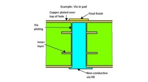
6. Pay Attention to Pad and Via Design: Use laser-drilled vias (0.1-0.2mm diameter) with metalized hole walls (copper thickness ≥8μm) for reliable conductivity. Space vias at least 0.5mm apart to avoid crowding and stress. For component pads match the pad size to the component package such as 01005 package pads 0.3mm×0.2mm and ensure pad edges are at least 0.1mm away from the cover layer to prevent solder overflow during assembly.
7. Comply with Industry Standards: Follow IPC-2223 (flexible circuit design standard) and JIS C 6481 (flexible printed circuit performance standard) to ensure your design meets quality and reliability requirements. For dynamic bending applications adhere to IPC-9701 to ensure the flexible assembly can withstand 100000+ bending cycles without failure. Compliance helps avoid costly rework and ensures compatibility with manufacturing processes.
8. Test the Design Before Mass Production: Use simulation software such as ANSYS Mechanical to test bending stress and signal integrity identifying potential stress points or impedance mismatches. Create a prototype of the flexible printed circuit and test it in your target device checking for bending durability signal transmission and fit. Conduct dynamic bending tests 100000 cycles 1Hz frequency and thermal cycling tests -40℃~85℃ to verify long-term reliability.
9. Avoid Common Design Mistakes: Steer clear of using rigid PCB materials for flexible printed circuits as they lack flexibility and will break. Do not route traces perpendicular to the bending direction as this causes rapid trace failure. Never skip reinforcement in connector areas as this leads to tearing during assembly or use. Avoid overcrowding traces or vias which increases crosstalk and manufacturing defects.
10. Optimize for Manufacturability: Design your flexible printed circuit with mass production in mind. Use standard material thicknesses and sizes where possible to reduce costs. Avoid overly complex shapes that are difficult to manufacture. Ensure the cover layer and reinforcements are easy to apply and align as this reduces production time and error rates. Work with your flexible circuit manufacturer to align your design with their equipment capabilities for smoother production.
What is the Difference between FFC vs FPC Cable?
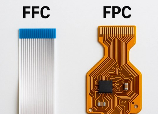
FFC (Flexible Flat Cable) and flexible printed circuits are often confused, but they have key differences in structure, design, and application. The table below clearly outlines these differences:
| Comparison Criteria | FFC Cable | Flexible Printed Circuit Cable |
| Cost-Effectiveness | Low cost, ideal for budget-friendly, high-volume projects | Higher cost, but worth it for specialized, high-performance needs |
| Flexibility | Basic flexibility; limited bending capability, not suitable for tight folds or twists | High flexibility; supports repeated folding and twisting, suitable for compact, moving applications |
| Customization | Limited; only standard sizes and pitches available, no custom modifications | Highly customizable; size, shape, and circuit layout can be tailored to specific device requirements |
| Application Suitability | Suitable for simple, low-density connections (e.g., printers, hard drives) | Suitable for complex, high-density connections in compact devices (e.g., smartphones, medical equipment) |
| Maintenance & Replacement | Easy to replace; standard specifications allow for quick sourcing | Custom replacement required; higher durability for long-term service |
FAQs About Flexible Printed Circuit Cable
Q1: How to clean FPC cable samsung tv?
A1: To clean an FPC cable in a Samsung TV, first power off the TV and unplug it from the power source. Remove the FPC cable from its connector using the proper disconnect method. Use a lint free cloth dipped in isopropyl alcohol (70% to 90% concentration) to gently wipe the gold fingers and the connector contacts. Avoid using excessive force or harsh chemicals, as they can damage the cable’s traces or insulation. Allow the cable and connector to dry completely before reinserting the FPC cable and powering on the TV.
Q2: Can FPC cable be cut lengthwise?
A2: No, FPC cable cannot be cut lengthwise. Cutting an FPC cable along its length will damage the conductive traces, which are printed parallel to the cable’s length. This damage will break the electrical connection and render the FPC cable useless. If you need a shorter FPC cable, cut it perpendicular to the length (across the width) using a sharp, clean tool, and ensure the cut is straight to avoid damaging the remaining traces.
Q3: How to replace sensor on FPC cable?
A3: To replace a sensor on an FPC cable, first disconnect the FPC cable from the device following the safe disconnect steps. Use a soldering iron to desolder the old sensor from the FPC cable’s pads, applying heat to the solder joints and gently lifting the sensor once the solder melts. Clean the pads with isopropyl alcohol to remove excess solder. Align the new sensor with the pads, apply flux, and solder the sensor in place, ensuring each pin is properly soldered without bridges. Reconnect the FPC cable to the device and test the sensor to verify functionality.
Q4: Can FPC cable be folded?
A4: Yes, FPC cable can be folded, and this is one of its key advantages. FPC cables are designed to withstand folding and bending, thanks to their flexible substrate and durable traces. However, folding must be done along the correct axis and within the minimum bending radius (typically 5 times the cable’s thickness). Avoid folding the FPC cable sharply or repeatedly in the same spot, as this can weaken the traces over time and cause damage.
Q5: How to repair FPC cables?
A5: Repairing an FPC cable depends on the damage. For small trace breaks, use conductive silver paste: clean the area, expose the broken trace by gently scraping the cover layer, apply conductive silver paste to bridge the break, and let it cure at a low temperature (typically 100-150℃) as recommended for the paste. For larger damage, use micro soldering to bridge the break with a thin wire. If the gold fingers are damaged, trim the damaged end and solder a new connector. For severe damage, replace the FPC cable entirely. Always test the repaired FPC cable for continuity before reinstalling it in the device.
You may also like


Tags: ffc vs fpc cable, FPC Cable, how to connect fpc cable, how to disconnect fpc cable, what is a fpc cable