Astra MT77 is an ultra-low-loss laminate and prepreg system for RF, microwave and mmWave PCB designs. Its low Df and stable Dk help control signal loss, impedance and phase at high frequencies.
Unlike standard FR-4, this material targets circuits where dielectric behavior directly affects signal quality. Core thickness, prepreg construction, copper roughness and process control still determine final PCB performance.
This guide explains material properties, Dk and Df, stackup selection, controlled impedance and common applications. It also covers cost, material comparison and PCB sourcing.
What Is Astra MT77 PCB Material?
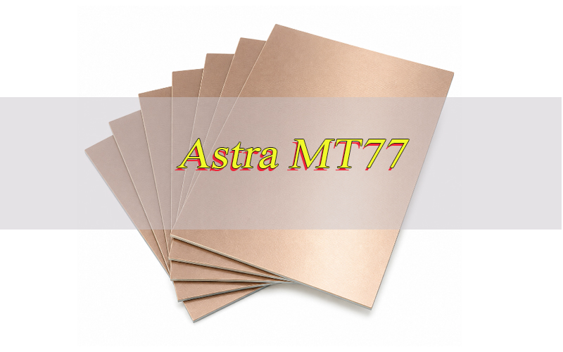
Astra MT77 is an ultra-low-loss RF and microwave laminate and prepreg material for high-frequency PCB applications. It is selected when stable impedance and low dielectric loss matter more than standard FR-4 cost.
The material is positioned as an alternative to PTFE and other commercial microwave laminates. Its fabrication is compatible with standard FR-4 PCB processing methods.
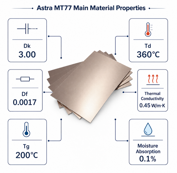
Typical values include Dk 3.00, Df 0.0017, Tg 200°C and Td 360°C. These properties support demanding RF and mmWave PCB structures.
In practice, the material often sits on critical RF or antenna layers. A hybrid stackup can use compatible materials on digital or control layers to reduce total material cost.
Why Is Astra MT77 Suitable for RF and mmWave PCB Designs?
Astra MT77 combines ultra-low dielectric loss, stable Dk and practical multilayer processing. This balance matters at high frequencies, where small material changes can affect loss and phase.
The main advantages include:
- Low dielectric loss: A typical Df of 0.0017 helps reduce dielectric loss.
- Stable Dk: A typical Dk of 3.00 supports predictable impedance and electrical length.
- W-band capability: The material supports demanding RF, microwave and mmWave structures.
- Temperature stability: Dk remains stable from -40°C to +140°C up to W-band frequencies.
- Smooth copper support: HVLP copper can reduce conductor-loss effects at high frequencies.
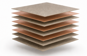
- Multilayer flexibility: Laminate and prepreg forms support complex RF PCB stackups.
- FR-4 process compatibility: Fabrication is less specialized than many PTFE material systems.
The main advantage is the balance of low loss, electrical stability and practical PCB processing.
Isola Astra MT77 Datasheet Overview: What Are the Main Material Properties?
The Isola Astra MT77 datasheet combines electrical, thermal and reliability data needed for high-frequency PCB material review. The table below summarizes the main published typical values.
| Property | Typical Value | Test Method |
|---|---|---|
| Tg by DSC | 200°C | IPC-TM-650 2.4.25C |
| Td at 5% Weight Loss | 360°C | IPC-TM-650 2.4.24.6 |
| T260 | >60 min | IPC-TM-650 2.4.24.1 |
| T288 | >60 min | IPC-TM-650 2.4.24.1 |
| Z-Axis CTE Pre-Tg | 50–70 ppm/°C | IPC-TM-650 2.4.24C |
| Z-Axis CTE Post-Tg | 250–350 ppm/°C | IPC-TM-650 2.4.24C |
| X/Y-Axis CTE Pre-Tg | 12 ppm/°C | IPC-TM-650 2.4.24C |
| Thermal Conductivity | 0.45 W/m·K | ASTM E1952 |
| Thermal Stress | Pass, 10 s at 288°C | IPC-TM-650 2.4.13.1 |
| Dk | 3.00 | IPC-TM-650 2.5.5.5 |
| Df | 0.0017 | Bereskin Stripline |
| Volume Resistivity | 1.33 × 10⁷ MΩ·cm | IPC-TM-650 2.5.17.1 |
| Surface Resistivity | 1.33 × 10⁵ MΩ | IPC-TM-650 2.5.17.1 |
| Dielectric Breakdown | 45.4 kV | IPC-TM-650 2.5.6B |
| Electric Strength | 45 kV/mm | IPC-TM-650 2.5.6.2A |
| Peel Strength | 1.0 N/mm | IPC-TM-650 2.4.8.3 |
| Moisture Absorption | 0.1% | IPC-TM-650 2.6.2.1A |
| Flammability | V-0 | UL 94 |
| RTI | 130°C | UL 796 |
Dk and Df define the core RF behavior. Tg, Td, CTE and thermal stress help assess multilayer and assembly reliability.
What Are the Dielectric Constant and Dissipation Factor of Astra MT77?
The typical Astra MT77 dielectric constant is 3.00, while the typical dissipation factor is 0.0017. These values affect impedance, electrical wavelength and dielectric loss.
Dk affects impedance and electrical length. Use the selected material value in microstrip, stripline and grounded coplanar waveguide calculations.
Df represents dielectric signal loss. The low dissipation factor helps limit loss as frequency and trace length increase.
However, do not assume every dielectric layer has exactly the same Dk. Published prepreg constructions range from Dk 2.91 to 3.01.
For controlled impedance, use the selected construction and final pressed dielectric thickness. This gives a more realistic model than one generic material value.
How to Choose the Right Astra MT77 Thickness for a PCB Stackup?
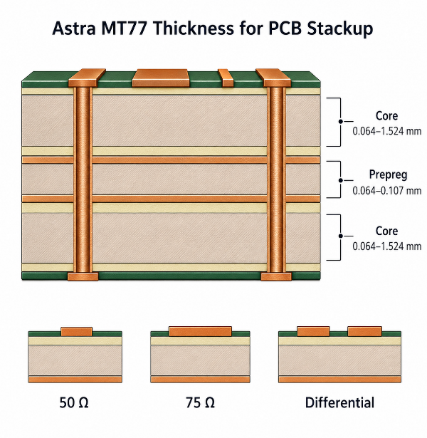
Choose Astra MT77 thickness from impedance, RF geometry, operating frequency and final PCB construction. The thinnest core is not automatically the best option.
- Start with the target impedance: Define 50 Ω, 75 Ω or the required differential impedance first.
- Review published core thicknesses: Standard core data includes 0.064 to 1.524 mm constructions.
- Check practical trace width: Very thin dielectrics may force narrow traces with tighter etching tolerance.
- Match the RF structure: Microstrip, stripline and grounded coplanar waveguide need different dielectric spacing.
- Model prepreg separately: Published prepreg constructions use Dk values from 2.91 to 3.01.
- Use realistic pressed thickness: Resin content, copper pattern and lamination affect finished dielectric spacing.
- Check total PCB balance: Keep copper distribution and dielectric construction mechanically balanced.
- Freeze the approved stackup: Late core or prepreg changes can alter impedance and electrical length.
The right thickness produces a manufacturable RF geometry with stable dielectric spacing.
How Should an Astra MT77 PCB Be Designed for Controlled Impedance?
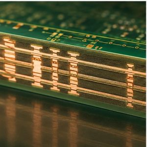
An Astra MT77 PCB should use a fixed stackup, exact dielectric construction and realistic finished copper geometry. Generic material values can create avoidable impedance error.
- Use construction-specific Dk: Match the model to the selected core or prepreg construction.
- Enter finished dielectric thickness: Use the expected pressed thickness, not only nominal raw material data.
- Include finished copper thickness: Base copper and plating change the final trace cross-section.
- Control copper roughness: HVLP copper is relevant when conductor loss becomes significant.
- Keep reference planes continuous: Avoid plane splits below critical RF traces and launches.
- Limit unnecessary layer changes: RF vias add inductance, capacitance and return-path discontinuities.
- Model connectors and launches: Include pads, antipads, transitions and nearby ground vias.
- Review solder mask coverage: Coating can change the local dielectric environment around surface RF lines.
- Add representative coupons: Match coupon layers, copper thickness and dielectric construction to the PCB.
- Set realistic fabrication tolerances: Line width and dielectric variation must fit the design margin.
At mmWave frequencies, the complete transmission structure affects impedance. Material data, geometry and fabrication control must work together.
How Do Tg, Td and Thermal Conductivity Affect Astra MT77 PCB Reliability?
Astra MT77 has a typical Tg of 200°C, Td of 360°C and thermal conductivity of 0.45 W/m·K. These values describe different reliability limits.
- Tg 200°C: A high Tg helps limit major expansion changes during thermal processing.
- Td 360°C: Td indicates material decomposition behavior at 5% weight loss.
- T260 and T288 above 60 minutes: These values indicate resistance to delamination under the stated TMA method.
- Thermal stress pass at 288°C for 10 seconds: This supports lead-free process evaluation.
- Z-axis CTE of 50–70 ppm/°C pre-Tg: Lower expansion before Tg helps plated-hole reliability.
- Post-Tg Z-axis CTE of 250–350 ppm/°C: Expansion rises after Tg and still matters during heat exposure.
- Thermal conductivity of 0.45 W/m·K: The dielectric conducts heat but is not a dedicated heat spreader.
- Moisture absorption of 0.1%: Low moisture uptake helps support stable material behavior.
Tg and Td are not the continuous operating temperature of a finished PCB. System thermal limits must be based on the complete assembly.
What Applications Commonly Use Astra MT77 PCB Material?
Common applications include:
- 77 GHz automotive radar
- Adaptive cruise control systems
- Pre-crash radar electronics
- Blind-spot detection systems
- Lane departure warning electronics
- Stop-and-go radar systems
- Long RF antenna structures
- Commercial RF and microwave circuits
- Aerospace and defense RF electronics
The material is most useful where low RF loss and stable high-frequency behavior create measurable system value.
Astra MT77 vs I-Tera MT40: Which Material Should You Choose?
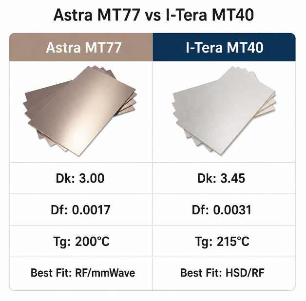
Choose Astra MT77 when ultra-low RF and mmWave loss is the main priority. Choose standard I-Tera MT40 for broader high-speed digital and RF PCB designs.
The comparison below uses standard I-Tera MT40 laminate and prepreg data. The separate I-Tera MT40 RF/MW range includes additional Dk constructions.
| Property | Astra MT77 | I-Tera MT40 |
|---|---|---|
| Primary Focus | RF/MW and mmWave | High-speed digital and RF/MW |
| Dk | 3.00 | 3.45 |
| Df | 0.0017 | 0.0031 |
| Tg by DSC | 200°C | 215°C |
| Td | 360°C | 360°C |
| Thermal Conductivity | 0.45 W/m·K | 0.61 W/m·K |
| Dk Temperature Range | -40°C to +140°C | -55°C to +125°C |
| Frequency Range | Up to W-band | Up to W-band |
| Material Forms | Laminate and prepreg | Laminate and prepreg |
| Processing | FR-4 process compatible | No special PTFE-type through-hole treatment |
| Best Fit | Loss-sensitive RF/mmWave | HSD, hybrid and RF/MW |
MT77 has the lower published Df and suits loss-sensitive RF paths. This includes radar and mmWave transmission structures.
I-Tera MT40 offers a broader fit for high-speed digital and mixed RF designs. It also has a higher published thermal conductivity.
Do not substitute either material without recalculating the stackup. Their Dk values differ, so identical trace geometry will not produce the same impedance.
What Affects Astra MT77 PCB and Laminate Cost?
Astra MT77 PCB cost depends on material construction, manufacturing complexity and RF control requirements. One price per square foot cannot represent every finished PCB project.
The main cost factors are:
- Material construction and availability: Non-standard cores or prepregs may increase sourcing time.
- Layer count: More layers increase material, lamination and inspection requirements.
- Copper type: Smooth or low-profile copper can affect material cost and availability.
- Controlled impedance tolerance: Tight limits require stackup review and coupon verification.
- Fine RF geometry: Narrow traces and small gaps increase process control requirements.
- Hybrid stackup complexity: Mixed materials require detailed lamination planning.
- Order quantity: Prototype and batch orders use material differently.
- Testing requirements: Microsection and impedance testing add inspection steps.
For an accurate laminate price, provide the exact material construction and order quantity. Finished PCB quotations also require Gerber data, stackup, copper weight and impedance targets.
Searches for MT77 price per square foot often overlook fabrication cost. Material price is only one part of the finished RF PCB cost.
Why Choose EBest Circuit as Your Astra MT77 PCB Manufacturer?
EBest Circuit helps reduce material, stackup and production risks before the PCB reaches volume manufacturing. Our China-based source factory supports custom production and global supply.
- Reduce stackup errors before fabrication: We review dielectric thickness, copper weight and RF layer arrangement early.
- Protect approved RF performance: Material traceability helps prevent uncontrolled laminate or prepreg substitution.
- Improve impedance consistency: Stackup, trace geometry and coupon requirements are checked before production.
- Move from prototype to batch production faster: One manufacturing route supports sample verification and volume transfer.
- Simplify complex RF sourcing: Multilayer, hybrid and controlled-impedance PCB requirements can be reviewed together.
- Match quality controls to the application: Electrical testing, microsection and impedance verification can follow project requirements.
- Support regulated industry programs: Our quality systems include ISO 9001, IATF 16949, ISO 13485 and AS9100D.
- Source directly from a China factory: Global supply is supported without false overseas factory or warehouse claims.
The benefit is lower production risk and better stackup control from quotation through batch manufacturing.
Send the approved material requirement, stackup and Gerber files for review. We can check manufacturability before production pricing is finalized.
FAQs About Astra MT77 PCB Material
Q1: Is Astra MT77 RoHS compliant?
A1: Yes. Astra MT77 is identified as RoHS compliant and is compatible with lead-free assembly. Finished PCB or PCBA compliance still depends on the full material set, surface finish, solder and components.
Q2: Which IPC specification recognizes MT77?
A2: The official material information lists IPC-4103/17. The applicable finished PCB acceptance or performance standard still depends on the product, industry and fabrication specification.
Q3: What UL recognition is listed for MT77?
A3: Isola lists UL File E41625 for the material. The published typical values table also lists a UL 94 V-0 flammability rating and 130°C RTI.
Q4: Is MT77 compatible with lead-free assembly?
A4: Yes. Lead-free assembly compatibility is listed as a product attribute. The datasheet also reports a 10-second thermal stress pass at 288°C under the stated test method.
Q5: What copper foil and copper weights are available?
A5: The datasheet lists HVLP copper at 2.5 µm Rz JIS or below as standard for 1 oz and below. Published copper weights range from 0.5 to 2 oz, with thinner foil also available.
Q6: Does MT77 always require plasma desmear?
A6: No. The material shows good response to chemical desmear. Plasma can improve thick or high-aspect-ratio holes. FR-4-level plasma etching is strongly recommended for laser microvias.
Q7: Can MT77 support HDI, any-layer and VIPPO structures?
A7: Yes. The datasheet lists HDI, any-layer and VIPPO compatibility. However, laser microvia cleaning, repeated lamination and plating still require process validation for the actual PCB construction.
Q8: Can MT77 be used through multiple lamination cycles?
A8: Yes. Multiple lamination cycles are listed among the material’s processing advantages. The lamination cycle still needs adjustment for package thickness and the selected multilayer construction.
Q9: How should MT77 prepreg be stored?
A9: Store prepreg at 23°C or below and below 50% humidity. Keep it in the original packaging until use. FIFO inventory control is also recommended.
Q10: Should opened MT77 prepreg be vacuum sealed?
A10: No. Remaining prepreg should be resealed in the original packaging with fresh desiccant. Isola’s processing guide specifically states not to vacuum seal MT77 prepreg.
Q11: How quickly should finished boards be processed after opening an MBB?
A11: The processing guide recommends processing within 168 hours when shop-floor conditions remain below 30°C and 60% RH. Opened MBBs should be resealed immediately after inspection.
Q12: What packaging is recommended for long shelf life?
A12: For high-temperature assembly and long shelf life, dry boards should use a Moisture Barrier Bag, Humidity Indicator Card and adequate desiccant. This helps limit moisture uptake during storage and shipment.
Q13: Is MT77 density published in the main datasheet?
A13: No. A typical MT77 density value is not listed in the main published property table. Do not copy a density value from another RF laminate for weight calculations.
Q14: What files should be sent for an MT77 PCB quotation?
A14: Send Gerber or ODB++ data, drill files, stackup, copper weight, finished thickness, quantity and impedance requirements. Also identify critical RF layers and the required material construction.
Q15: Can finished MT77 laminate use standard aqueous imaging and common etchants?
A15: Yes. Isola’s processing guide states that the laminate can use standard aqueous dry films. It is also compatible with cupric chloride and ammoniacal etchants.
Astra MT77 combines Dk 3.00, Df 0.0017 and stable high-frequency performance for demanding RF and mmWave PCB designs. The right result depends on exact material construction, realistic impedance modeling and controlled fabrication.
Choose this material when ultra-low RF loss justifies a specialized laminate system. Lock the stackup, copper construction and testing requirements before batch production.
Planning a 77 GHz radar, microwave or low-loss RF PCB? Send your Gerber files, stackup, impedance targets and quantity to sales@bestpcbs.com. EBest Circuit will review the manufacturing requirements and prepare a quotation for prototype or batch production.