PCB manufacturing PCB manufacturing
Home > Blog

How to Maintain, Test and Wire Your Arcade PCB Properly?

April 14th, 2026

Are you struggling with maintaining, testing or wiring your arcade PCB? Clear, actionable steps for every critical arcade PCB task are available here. These easy-to-follow tips align with industry best practices to ensure reliability and safety, covering identification, power, testing, cleaning and usage. Let’s start with the basics.

Arcade PCB, https://www.bestpcbs.com/blog/2026/04/arcade-pcb/

What is an Arcade PCB?

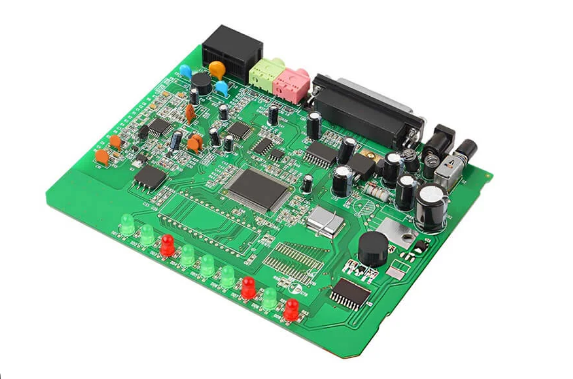
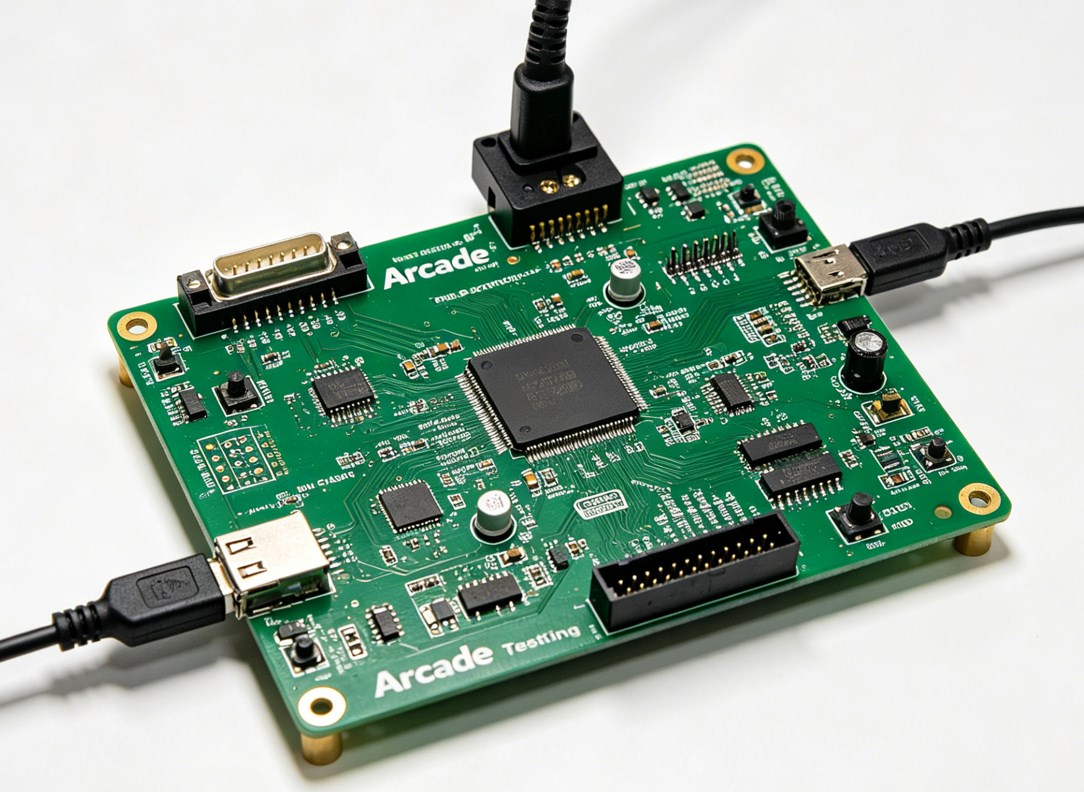
An arcade PCB (Printed Circuit Board) is the core component of any arcade machine, acting as its “brain” and “heart.” It contains all essential parts for game operation, including CPU, RAM, graphics and audio chips, ROM chips (for game software), voltage regulators, and connectors for controls, displays, and power.

Unlike standard PCBs, arcade PCBs are custom-made for specific games, with circuitry tailored to each game’s unique gameplay, graphics, and sound. Without a functional PCB, an arcade cabinet is non-operational, as all game logic, visuals, and audio depend on it.

Arcade PCBs come in different form factors, single-board (classic games) and multi-board (complex modern arcades), and vary by era, with older 8-bit/16-bit models having simpler components than modern ones with multi-core processors. Regardless of type, their core purpose is to turn electronic signals into an interactive arcade gaming experience.

How to Identify Arcade PCB?

Identifying an arcade PCB is straightforward once you know what to look for start with the most visible features, then move to component details. The first step is to check for labels or silk-screened text on the board itself; most manufacturers print the game title, model number, or manufacturer name directly on the PCB (usually near the edge or center). If no label exists, focus on the components and form factor.

Use this table to compare key identifying features of common arcade PCB types, making it easy to distinguish between models:

PCB TypeKey Identifying FeaturesCommon Examples
Single-Board ClassicSmall to medium size (6-12 inches), 8-16 ROM chips, silk-screened game title, edge connector for power/controlsPac-Man, Space Invaders, Donkey Kong
Multi-Board SystemMultiple connected PCBs (CPU, graphics, sound), larger size, more components, separate power connectors for each boardStreet Fighter II, Mortal Kombat, Tekken
Modern Arcade PCBSlim design, fewer physical components (integrated chips), USB or HDMI connectors, compatibility with modern displaysNewer fighting games, racing arcades, retro console ports
Bootleg PCBNo brand labeling, mismatched components, poor soldering, generic silk-screen textUnlicensed copies of classic games

Additional tips: Count the IC chips (integrated circuits) with 8 or more pins this can help narrow down the game type. Check for a notch or arrow on the PCB, which indicates the orientation of components like ROM chips. If you’re still unsure, take clear photos of the board (both sides) and compare the component layout to known arcade PCB databases or repair guides.

How Much Voltage Does Arcade PCB Need?

Most arcade PCBs require three primary DC voltages to operate, with +5V being the most critical. The exact voltage requirements vary slightly by PCB model, but the standard ranges are consistent across most arcade machines. You must match the voltage supply to the PCB’s specifications too much voltage will fry components, while too little will cause the game to malfunction or not start at all.

Here’s the breakdown of standard arcade PCB voltage requirements, organized by importance:

  • +5V DC: This is the primary voltage for the PCB’s core components (CPU, RAM, ROM chips, logic circuits). 90% of arcade PCBs use +5V as their main power source, with a tolerance of ±0.2V (so 4.8V to 5.2V is acceptable). A stable +5V supply is non-negotiable fluctuations will cause game crashes, glitches, or permanent component damage.
  • +12V DC: Used for audio amplifiers, coin door lights, LED strips, and some auxiliary components. Most PCBs draw minimal current from +12V, but it’s still required for full functionality (especially sound). The tolerance here is ±0.5V (11.5V to 12.5V).
  • -5V DC: Less common in modern arcade PCBs, but essential for sound circuits in older games (1980s and early 1990s). If your PCB has a dedicated sound chip (e.g., YM2612), it may require -5V with a tolerance of ±0.2V (-5.2V to -4.8V). Newer PCBs often omit -5V, as their sound circuits are powered by +5V or +12V.

Amperage is just as important as voltage. Most arcade PCBs require a power supply that can deliver 2-5 amps (A) at +5V, 1-2A at +12V, and 0.5A or less at -5V (if needed). Always check the PCB’s silk-screen or the game manual for exact amperage requirements using a power supply with insufficient amperage will cause voltage drops and system failures.

How to Check Arcade PCB Voltage?

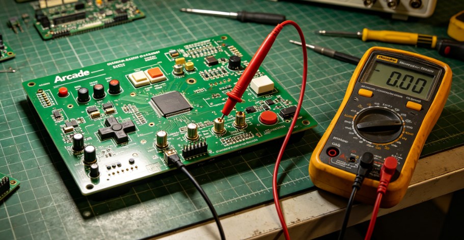
Checking arcade PCB voltage is a simple process that requires a digital multimeter no advanced tools needed. The goal is to verify that the PCB is receiving stable, correct voltage from the power supply, which helps diagnose issues like game crashes, no power, or glitches. Follow these steps exactly to avoid damaging the PCB or multimeter:

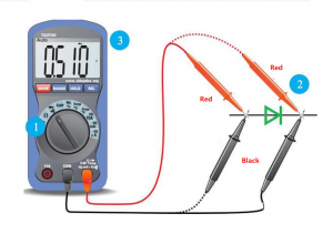
1. Prepare the tools: Get a digital multimeter, and set it to DC voltage mode (look for the “V⎓” symbol). Set the range to 20V (this covers all standard arcade voltages, so you won’t need to adjust it). Ensure the multimeter’s batteries are working test it by touching the two probes together; it should read 0V.

2. Power off the arcade machine: Unplug the power cord from the wall outlet to avoid electric shock. Wait 30 seconds to allow capacitors to discharge this prevents residual voltage from interfering with the test.

3. Locate the power connector on the PCB: The power connector is usually a small plastic block with pins labeled “+5V,” “+12V,” “-5V,” and “GND” (ground). If the labels are missing, refer to the PCB’s silk-screen or game manual to identify the pins.

4. Power on the machine: Plug the power cord back in and turn on the arcade machine. Do not touch any components on the PCB while it’s powered on static electricity or accidental contact can damage sensitive chips.

5. Test the voltage: Hold the multimeter’s black probe (negative) firmly against the GND pin. Use the red probe (positive) to touch the +5V pin first. The multimeter should read between 4.8V and 5.2V. Repeat for the +12V pin (11.5V to 12.5V) and -5V pin (-4.8V to -5.2V, if present).

6. Interpret the results: If the voltage is within the acceptable range, the power supply is working correctly. If it’s too high or too low, the power supply is faulty and needs to be replaced. If the voltage fluctuates (e.g., jumps from 4.5V to 5.5V), the power supply is unstable and should be replaced immediately to prevent PCB damage.

    Pro tip: Test the voltage at both the power supply connector and the PCB’s power pins. If the voltage is correct at the power supply but incorrect at the PCB, there’s a loose wire or damaged connector that needs to be fixed.

    Arcade PCB, https://www.bestpcbs.com/blog/2026/04/arcade-pcb/

    How to Hook Up Arcade PCB?

    Hooking up an arcade PCB is a step-by-step process that requires connecting power, controls (joysticks, buttons), display, and sound. The key is to match the PCB’s connectors to the corresponding components in the arcade cabinet misconnections will cause malfunctions or damage. Follow these steps for a safe, successful setup:

    1. Prepare the cabinet: Ensure the arcade cabinet is powered off and unplugged. Remove the back panel to access the interior. Clear any dust or debris from the cabinet to avoid short circuits.

    2. Mount the PCB: Use screws to secure the PCB to the cabinet’s mounting bracket. Ensure the PCB is level and not touching any metal components (this prevents short circuits). Use standoffs if needed to elevate the PCB slightly.

    3. Connect the power supply: Plug the power supply’s connector into the PCB’s power port. Match the pins carefully most power connectors are keyed (have a notch) to prevent reverse insertion, but double-check the labels (+5V, +12V, -5V, GND) to be sure. Do not force the connector if it doesn’t fit, it’s oriented incorrectly.

    4. Connect controls: The PCB has a dedicated connector for joysticks and buttons (often called a “control harness”). Plug the control harness into the PCB’s control port. Each button and joystick direction is wired to a specific pin refer to the PCB’s manual to ensure the harness is connected correctly. Test the controls by pressing buttons and moving the joystick; if they don’t respond, check the wiring.

    5. Connect the display: Most arcade PCBs use a VGA, HDMI, or RGB connector for the display. Plug the display cable into the PCB’s display port and the other end into the arcade’s monitor. Ensure the display is set to the correct resolution (most classic PCBs use 4:3 aspect ratio).

    6. Connect sound: Plug the speaker wires into the PCB’s audio port (labeled “AUDIO OUT” or “SPEAKER”). If the PCB has separate left and right audio channels, connect each wire to the corresponding speaker.

    7. Test the setup: Plug in the power cord and turn on the arcade machine. The game should boot up, and all controls, display, and sound should work. If there’s no power, check the power supply and connections. If the game boots but controls don’t work, recheck the control harness.

      Pro tip: Take photos of the original PCB’s connections before removing it (if replacing an old PCB). This makes it easy to match the wiring to the new PCB.

      How to Connect Speakers to Arcade PCB?

      Connecting speakers to an arcade PCB is simple, but you must match the speaker’s impedance (ohms) to the PCB’s audio output to avoid damaging the sound chip. Most arcade PCBs work with 8-ohm or 4-ohm speakers check the PCB’s silk-screen or manual for the exact impedance requirement. Follow these steps to connect speakers correctly:

      1. Gather the tools: You’ll need speakers (matching the PCB’s impedance), speaker wire (18-22 gauge), wire strippers, and electrical tape (or heat shrink tubing).

      2. Prepare the speaker wire: Cut two lengths of speaker wire (long enough to reach from the PCB to the speakers). Strip 1/4 inch of insulation from each end of the wire to expose the copper strands. Twist the strands together to prevent fraying.

      3. Locate the PCB’s audio port: The audio port is usually labeled “AUDIO OUT,” “SPEAKER,” “LEFT,” or “RIGHT.” Most PCBs have two terminals (positive and negative) for each speaker look for “+” and “-” labels.

      4. Connect the wire to the PCB: Attach one end of the speaker wire to the PCB’s positive terminal (+) and the other end to the negative terminal (-). Use electrical tape to secure the wires to the terminals this prevents them from coming loose.

      5. Connect the wire to the speaker: Attach the other end of the wire to the speaker’s positive and negative terminals (match “+” to “+” and “-” to “-”). Again, secure the wires with electrical tape or heat shrink tubing.

      6. Test the sound: Turn on the arcade machine and play a game. The sound should be clear and free of distortion. If there’s no sound, check the wire connections (ensure they’re secure and matched correctly) or test the speakers with another device to confirm they’re working.

        Note: If the PCB has a built-in audio amplifier, you can connect speakers directly. If not, you’ll need an external amplifier between the PCB and speakers connect the PCB’s audio output to the amplifier, then the amplifier to the speakers.

        How to Test Arcade PCB?

        Testing an arcade PCB ensures it’s functional before installing it in a cabinet, saving you time and frustration. The test covers power, graphics, sound, and controls, and requires a few basic tools: a power supply (matching the PCB’s voltage), a display (monitor or TV), speakers, and a control harness (joystick and buttons). Follow these steps to test the PCB thoroughly:

        1. Set up the test bench: Place the PCB on a non-conductive surface (e.g., a wooden table) to prevent short circuits. Connect the power supply to the PCB’s power port ensure the voltage and amperage match the PCB’s requirements.

        2. Connect the display: Plug the display cable into the PCB’s display port and turn on the display. Set the display to the correct input (e.g., VGA, HDMI).

        3. Connect speakers: Attach speakers to the PCB’s audio port (as outlined in the previous section).

        4. Connect controls: Plug the control harness (joystick and buttons) into the PCB’s control port.

        5. Power on the PCB: Turn on the power supply. The PCB should power up within 2-3 seconds, and the display should show the game’s title screen or boot sequence.

        6. Test graphics: Check for clear, distortion-free visuals. Look for glitches, missing sprites, or color issues these indicate a faulty graphics chip or ROM.

        7. Test sound: Play the game and listen for clear audio. Check for static, distortion, or missing sound effects this could mean a faulty sound chip or speaker connection.

        8. Test controls: Press all buttons and move the joystick in all directions. Ensure each input is registered in the game (e.g., the character moves when the joystick is pushed, buttons trigger actions).

        9. Test stability: Let the game run for 10-15 minutes. If it crashes, freezes, or resets, there’s a problem with the power supply, overheating, or a faulty component (e.g., a bad ROM chip).

          If the PCB fails any test: Check the power supply voltage (as outlined earlier), inspect for loose components or damaged traces, and test the ROM chips (see the next section). For more complex issues, use a multimeter to check for continuity in the PCB’s traces.

          How to Use an Arcade PCB?

          Using an arcade PCB is simple once it’s properly hooked up, but there are a few key steps to ensure optimal performance and longevity. Whether you’re using a classic or modern PCB, follow these guidelines to get the most out of your arcade machine:

          1. Power on correctly: Always turn on the arcade machine’s power supply first, then the display. This prevents voltage spikes from damaging the PCB’s components. When turning off, reverse the order: turn off the display first, then the power supply.

          2. Monitor temperature: Arcade PCBs generate heat during operation, especially older models. Ensure the cabinet has proper ventilation (e.g., fans, vents) to prevent overheating. Avoid placing the cabinet in direct sunlight or near heat sources (e.g., radiators).

          3. Handle with care: Never touch the PCB’s components while it’s powered on. If you need to adjust connections or inspect the board, turn off the power and unplug the machine first. Use an anti-static wristband to prevent static discharge, which can destroy sensitive chips.

          4. Load games correctly: For PCBs with removable ROM chips, ensure the chips are seated properly (see the next section) before powering on. If the game doesn’t load, check the ROM chips for damage or misalignment.

          5. Perform regular checks: Every 1-2 months, power off the machine, unplug it, and inspect the PCB for dust, loose components, or corrosion. Clean the PCB (as outlined below) to prevent dust buildup, which can cause short circuits.

          6. Troubleshoot minor issues: If the game glitches or freezes, power off the machine, wait 30 seconds, then power it back on. This often resolves temporary issues caused by voltage fluctuations or overheating. If the problem persists, check the power supply and connections.

            Pro tip: For vintage PCBs, avoid leaving the machine on for extended periods (e.g., 8+ hours) to reduce wear on components. Modern PCBs are more durable but still benefit from occasional breaks to prevent overheating.

            Arcade PCB, https://www.bestpcbs.com/blog/2026/04/arcade-pcb/

            How to Clean Arcade PCB?

            Cleaning an arcade PCB is critical for preventing malfunctions dust, dirt, and corrosion can cause short circuits, poor connections, and component failure. The process is simple but requires care to avoid damaging sensitive components. Use only the right tools and cleaning solutions to ensure safety and effectiveness:

            1. Prepare the tools: You’ll need high-purity isopropyl alcohol (IPA, 90% or higher) or anhydrous ethanol (99% or higher), anti-static wristband, soft-bristled brush (e.g., an old toothbrush), lint-free cloths (or coffee filters), and a small container for the cleaning solution. Avoid low-purity alcohol as it contains too much water and can cause corrosion.

            2. Power off and disconnect: Unplug the arcade machine and remove the PCB from the cabinet. Put on the anti-static wristband to prevent static discharge. Place the PCB on a non-conductive surface.

            3. Remove loose dust: Use the soft-bristled brush to gently sweep away loose dust and debris from the PCB’s surface and components. Be careful not to bend any pins or damage small components (e.g., capacitors).

            4. Clean with alcohol: Pour a small amount of IPA or ethanol into the container. Dip the lint-free cloth or a cotton swab into the solution (don’t soak it just dampen it). Gently wipe the PCB’s surface, focusing on areas with visible dirt, grease, or corrosion. For hard-to-reach areas (e.g., between components), use a cotton swab.

            5. Clean connectors and pins: Use a cotton swab dampened with alcohol to clean the PCB’s edge connector and component pins. This removes oxidation and dirt that can cause poor connections.

            6. Dry the PCB: Allow the PCB to air dry in a well-ventilated area for at least 30 minutes (or overnight for best results). Do not use a hair dryer or heat source this can damage components. Ensure the PCB is completely dry before reconnecting it to the power supply.

            7. Reassemble: Once dry, reattach the PCB to the cabinet and reconnect all cables. Power on the machine to confirm it’s working correctly.

              Note: Avoid using water, harsh chemicals, or abrasive materials (e.g., paper towels) as these can damage the PCB’s solder mask and components. For heavy corrosion, use a specialized electronic cleaner (ensure it’s compatible with PCBs) and a small brush to gently remove the corrosion.

              How to Remove ROM Chips from Arcade PCB?

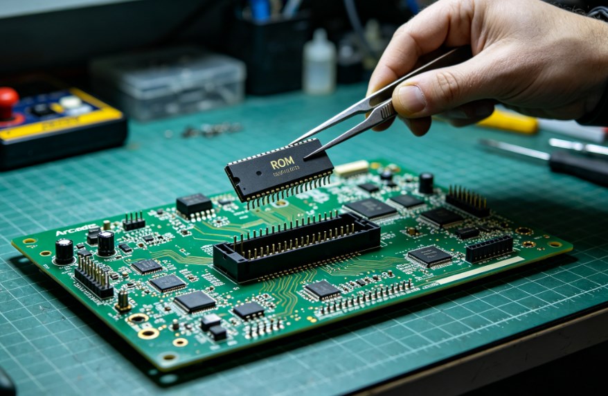
              ROM chips (Read-Only Memory) store the game’s software, and removing them may be necessary for repairs, upgrades, or replacement. The process requires care to avoid damaging the ROM chip or the PCB’s socket. Follow these steps to safely remove ROM chips:

              1. Prepare the tools: You’ll need an EPROM puller (preferred) or a small flathead screwdriver, anti-static wristband, and a clean, dry surface to place the ROM chips.

              2. Power off and disconnect: Unplug the arcade machine and remove the PCB from the cabinet. Put on the anti-static wristband to prevent static discharge.

              3. Locate the ROM chips: ROM chips are rectangular integrated circuits (ICs) with 16-40 pins, usually seated in a socket on the PCB. They are often labeled with the game’s title or a part number.

              4. Identify the notch: Each ROM chip has a small notch on one end, which indicates pin 1. The PCB’s socket will also have a notch or arrow to match the chip’s orientation note this before removing the chip to ensure correct reinstallation.

              5. Remove the chip: If using an EPROM puller, clamp the puller around the edges of the ROM chip (avoid touching the pins) and gently pull straight up. If using a screwdriver, insert the flathead between the chip and the socket (on one side) and gently twist to lift the chip slightly. Move the screwdriver to the other side and repeat until the chip is loose, then pull it straight up. Do not pry too hard this can damage the socket or the chip’s pins.

              6. Store the chip: Place the removed ROM chip on an anti-static mat or in an anti-static bag. Label the chip with the game title and its position on the PCB (e.g., “ROM 1”) to avoid confusion if you’re reinstalling it later.

                Pro tips: Remove one ROM chip at a time to avoid mixing them up. If the chip is stuck, gently rock it back and forth (without bending the pins) to loosen it. Never remove or insert ROM chips while the PCB is powered on this will fry the chip and possibly the PCB.

                Arcade PCB, https://www.bestpcbs.com/blog/2026/04/arcade-pcb/

                FAQs About Arcade PCB Board

                Q1: Why won’t my arcade PCB power on even with the correct voltage?

                A1: Common issues: loose power connections, faulty power supply, damaged power connector. Check connections, test power supply with a multimeter, clean or replace damaged connector; replace faulty voltage regulator if needed.

                Q2: How do I know if my arcade PCB’s ROM chips are bad?

                A2: Signs: game crashes, missing graphics, distorted sound, blank screen. Check ROM seating first; test with an EPROM programmer if issues persist. Replace bad ROM chips matching the game’s model and part number.

                Q3: Can I use a different power supply for my arcade PCB?

                A3: Only if it matches voltage (±tolerance), amperage (≄ requirement) and polarity. Reverse polarity will damage components; check power supply specs first.

                Q4: How often should I clean my arcade PCB?

                A4: Every 3-6 months (2-3 months in dusty areas). Clean immediately if corrosion, grease or dirt is present; power off and unplug before cleaning.

                Q5: Can I repair a broken trace on my arcade PCB?

                A5: Yes. Locate the break with a multimeter (continuity mode), clean the area, solder a 22-24 gauge copper wire across the break, and test after cooling.

                Q6: What’s the difference between a bootleg arcade PCB and an original one?

                A6: Original: official manufacture, high-quality components, clear labeling, proper soldering, reliable. Bootleg: unlicensed, cheap components, poor soldering, no branding, prone to glitches and failure.

                Q7: How do I prevent static damage to my arcade PCB?

                A7: Wear an anti-static wristband, hold PCB by edges, store in anti-static bag, work on non-conductive surfaces, avoid static-generating materials and clothing.

                You may also like

                How to Desolder a Circuit Board for Beginners?

                April 13th, 2026

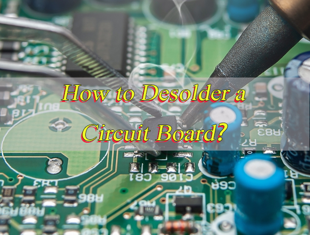
                How to desolder a circuit board without damaging its pads, components, or traces? If you’re a beginner worried about ruining your PCB, this guide gives you simple, safe step-by-step methods for desoldering common PCB components. It covers through-hole pins, chips, SMD parts, HDMI ports, and small components with straightforward, actionable steps. You don’t need fancy tools or knowledge of confusing terms, and it will help you get the job done right the first time.

                How to Desolder a Circuit Board for Beginners, https://www.bestpcbs.com/blog/2026/04/how-to-desolder-a-circuit-board/

                How to Desolder a Circuit Board for Beginners?

                For beginners, the easiest and safest way to learn how to desolder a circuit board is to use a temperature-controlled soldering iron, desoldering pump, and flux. Start with simple through-hole parts, melt the solder completely, use the desoldering pump to remove it cleanly, and lift components gently. Do not force them. This method prevents lifted pads, broken traces, and board damage while building consistent skills.


                1. Prepare your workspace with a stable mat to keep the PCB from moving during operation. Ensure there is good lighting so you can clearly see the solder joints and small components.
                2. Wear an anti-static wristband to prevent static electricity from damaging sensitive components on the PCB.
                3. Check that your temperature-controlled soldering iron is in good condition and the tip is clean with no obvious oxidation.
                4. Set your soldering iron to the correct temperature. Use 320–360°C for leaded solder and 340–380°C for lead-free solder. Do not set the temperature too high to avoid overheating the PCB.
                5. Clean the iron tip with a cleaning sponge to remove any dirt or old solder. Then apply a small amount of fresh solder to the tip to improve heat transfer.
                6. Take the flux and apply a small amount to the solder joint you want to desolder. Flux helps lower the melting temperature of the solder and makes it flow more easily.
                7. Hold the soldering iron tip against the solder joint and heat it evenly. Do not heat the joint for more than 4 seconds at a time to prevent damaging the PCB pad.
                8. Once the solder fully melts and becomes liquid, quickly use the desoldering pump to suck up all the molten solder. Press the pump’s plunger before heating, then release it immediately after the solder melts.
                9. If there is still some residual solder left on the pad or via, use solder wick to clean it. Place the solder wick on the residual solder and heat it with the soldering iron until the wick absorbs the excess solder.
                10. For multi-pin components, repeat steps 26 to 29 for each pin. Make sure all solder is removed from every pin before attempting to lift the component.
                11. After all solder is removed, use anti-static tweezers to grip the component firmly. Lift it straight up slowly to avoid damaging the PCB pads or traces.
                12. Dip a lint-free swab in 90%+ isopropyl alcohol and wipe the area where you desoldered the component. This cleans up leftover flux residue.
                13. Inspect the PCB pad carefully to check for any damage. Look for lifted pads, broken traces or residual solder that needs to be cleaned.

                How to Desolder Pins and Through-Hole Components?

                For beginners desoldering pins and through-hole components, always remove all solder from each pin before taking the component off the PCB. Pulling the component with leftover solder will easily damage PCB pads or break component pins. Removing all solder first keeps pads intact and makes component removal simple.

                1. Take flux and put a little on each pin joint of the component. Flux helps solder melt faster and flow better, so you don’t have to heat the joint as long. This keeps the PCB from getting damaged. You can also dip the tip of the desoldering pump in flux first, it will pick up more solder that way.
                2. Set your soldering iron to the right temperature for your solder (320–360°C for leaded, 340–380°C for lead-free). Hold the iron tip on one pin until the solder on the joint melts completely.
                3. Before heating the pin, press down the plunger on the desoldering pump to get it ready. As soon as the solder turns liquid, let go of the plunger to suck up all the melted solder.
                4. After using the pump, check the pin and the pad around it. If there’s any solder left on the pad or in the small hole (via), use solder wick to clean it. Put the wick on the leftover solder, then hold the iron tip on the wick until it soaks up the extra solder.
                5. Move to the next pin and do the same thing. If needed, add a little more flux, heat the pin until the solder melts, suck it up with the pump, and clean any residue with solder wick. Keep doing this for every pin on the component.
                6. Once all solder is removed from all pins, take anti-static tweezers and hold the component firmly but gently. Lift it straight up slowly. If it feels stuck, you can wiggle it just a little, but never pull hard or twist it. Pulling or twisting will tear the PCB pads.
                7. After taking the component off, if the small holes (vias) on the PCB are clogged with leftover solder, use a small drill bit or thin needle to clear them. Be very gentle so you don’t damage the hole or the pad around it.

                The following is a comparison table of desoldering methods:

                MethodBest ForSpeedPad SafetyEase for Beginners
                Desoldering PumpMost through-hole pins & connectorsFastGoodVery Easy
                Solder WickResidual solder, flat pad cleaningMediumExcellentVery Easy
                Dual-Iron HeatingLarge multi-pin partsFastModerateIntermediate

                How to Desolder a Chip from a Circuit Board Safely?

                For beginners desoldering pins and through-hole components, learning how to desolder properly is crucial: always remove all solder from each pin before taking the component off the PCB. Pulling the component with leftover solder will easily damage PCB pads or break component pins. Removing all solder first keeps pads intact and makes component removal simple.

                1. Mark the chip’s orientation with a small non-toxic marker first. Locate the small dot or notch on one corner of the chip; this is the pin 1 indicator. Draw a matching mark on the PCB next to this corner to ensure correct alignment when reinstalling the chip. Installing a chip backwards can damage both the chip and the PCB.
                2. Apply a generous amount of flux to all pin rows of the chip using a flux pen. Ensure each pin and its underlying pad are covered with a thin layer of flux. Flux lowers solder’s melting point, improves heat transfer, and prevents solder from sticking, making it easier to remove solder cleanly and protect the PCB.
                3. Use a 1.0mm or smaller fine-tip soldering iron set to 320–360°C for leaded solder or 340–380°C for lead-free solder. Start with one pin row: hold the iron tip on the first pin until the solder melts, then use a desoldering pump to suck up the molten solder. Use solder wick to remove any remaining solder on the pin or pad, and repeat this for every pin in the row.
                4. Repeat the process for the next pin rows, working slowly. For multi-pin chips like QFP or SOIC, speed up the process with drag soldering: apply extra flux to the row, heat the entire row by moving the iron back and forth, then use solder wick to absorb all molten solder at once. Continue until all pins are free of solder.
                5. If the chip is still stuck after removing visible solder, gently heat one corner’s pins for 2–3 seconds with the iron to melt hidden residual solder. Use anti-static tweezers to lift the chip slightly while heating. Never force it; if stuck, stop heating, add more flux, and try again. For stubborn chips, add a small amount of fresh solder to the corner pins to help melt old solder.
                6. After removing the chip, clean the PCB pads and chip pins (if reusing) with flux remover or 90%+ isopropyl alcohol. Use a lint-free swab to wipe each pad and pin individually to remove flux residue and leftover solder. This prepares the area for new chip installation and ensures good solder connections.

                For SOIC, QFP, or similar chips, hot air rework provides more even heating and reduces pad damage. Always keep heat moving to avoid burning the PCB or chip body.

                How to Desolder a Chip from a Circuit Board

                How to Desolder SMD Components With a Soldering Iron?

                You can easily desolder small SMD resistors, capacitors, and transistors using only a soldering iron, tweezers, and flux. The key is to heat one pad at a time, lift the component slightly, then free the other side.

                1. Set your iron to 300–330°C with a fine conical tip for precision.
                2. Add a small amount of flux to both SMD pads to reduce solder adhesion.
                3. Heat one end pad until solder melts, then use tweezers to lift that side of the component.
                4. Move the iron to the second pad, melt the remaining solder, and slide the part away completely.
                5. Clean both pads with solder wick to create a flat, smooth surface.
                6. Check for solder bridges and remove any excess with flux and wick.

                This method works perfectly for 2-pin SMD parts like resistors and capacitors. For 3–4 pin SMD transistors, alternate heating adjacent pins to release the part gradually.

                How to Desolder Circuit Board Components?

                Different types of circuit board components have unique desoldering requirements. Choosing the right technique for each component helps beginners work efficiently and avoid damaging the PCB or parts. Whether you’re working with through-hole parts, SMD components, or multi-pin devices, following component-specific steps ensures clean, safe desoldering.

                • Through-hole resistors and diodes: Use a desoldering pump to remove solder from one pin first. Gently bend the component lead slightly to separate it from the PCB pad. Then desolder the second pin completely and pull the component out. This method prevents stress on the PCB pads and component leads.
                • Through-hole capacitors: Heat and desolder both pins quickly, one after the other. Capacitors are sensitive to prolonged heat, so minimizing heat exposure protects the capacitor body from damage. Once both pins are free of solder, lift the capacitor straight up.
                • Large connectors and ports: Desolder each pin individually with a desoldering pump. Take your time to clear all solder from each pin before attempting to move the connector. Never twist or pull the connector until every pin is fully free, as this can tear PCB pads or break connector pins.
                • Small SMD components: Apply flux to both pads of the SMD part. Heat one pad with a fine-tip soldering iron until the solder melts, then use tweezers to lift that side of the component. Move the iron to the second pad, melt the remaining solder, and slide the component away. Clean both pads with solder wick afterward.
                • Integrated circuits and chips: Focus on removing solder from all pins evenly. Use a fine-tip iron and solder wick to clear each pin, or use drag soldering for multi-pin chips. Ensure no solder remains on any pin before lifting the chip with anti-static tweezers to avoid pad damage.
                How to Desolder Circuit Board Components

                How to Desolder an HDMI Port on a PCB?

                To desolder an HDMI port properly, you need to remove solder evenly from all through-hole pins and mounting tabs. Its closely spaced pins and delicate pads mean rushing or using too much force can damage the port or PCB. Follow these simple steps for safe, clean desoldering.

                1. Secure the PCB to a heat-resistant mat with double-sided tape or holders to keep it stable. Ensure the HDMI port is accessible, the board is flat, and you have good lighting to see pins clearly.
                2. Wear an anti-static wristband. Apply liquid flux to all HDMI pins and side mounting tabs with a flux pen to make solder removal easier and protect the PCB.
                3. Set your soldering iron to 320–360°C (leaded solder) or 340–380°C (lead-free). Use a 1.0mm fine tip, clean and tin it first. Heat each pin for 2–3 seconds until solder melts, then use a pre-primed desoldering pump to suck up the molten solder. Repeat for every pin.
                4. Apply extra flux to the side mounting tabs. Heat one tab for 2–3 seconds until solder melts, then gently lift it with anti-static tweezers to break the bond. Repeat for all tabs.
                5. Grip the HDMI port by its plastic housing with tweezers. Lift it straight up slowly—do not twist or pull hard. If stuck, check for leftover solder, reheat with flux, and try again.
                6. After removing the port, clean residual solder from pads with solder wick. Wipe pads with a lint-free swab dipped in 90%+ isopropyl alcohol and let it dry completely.
                7. For stubborn pins, add a little fresh solder to help melt old solder. Reheat for 2–3 seconds, suck it up with the pump, and repeat until the pin is free.

                After desoldering, check PCB pads for damage. If pads or traces are damaged, use a small jumper wire to restore connectivity before installing a new HDMI port.

                How to Desolder Small Components Without Damaging Pads?

                The most reliable way to desolder small components without pad damage is to use sufficient flux, controlled heat, and vertical lifting only. Lateral force, overheating, and prying are the main causes of lifted pads, which can break electrical connectivity and render the PCB unusable. For beginners, focusing on gentle, precise steps is key to avoiding this common issue.

                1. Use a fine soldering tip (≀1.2mm) for better precision, as small components have tiny pads that require targeted heating. Set your soldering iron to 300–330°C and limit heating to 2–3 seconds per pad. This prevents overheating the PCB substrate and lifting the delicate pads.
                2. Always apply flux before heating the solder joint. Use a flux pen for precise application, adding a thin layer to both the component pin and the PCB pad. Flux helps reduce solder adhesion, lowers the melting temperature, and minimizes the heat needed, which protects both the pad and the component.
                3. Use solder wick to remove excess solder instead of prying components off pads. Place the solder wick over the residual solder, heat it gently with the soldering iron, and let the wick absorb the excess. Prying can easily tear pads, so this method is much safer for small, delicate components.
                4. Lift components straight up with anti-static tweezers. You should avoid side-to-side pulling, as this creates lateral force that can separate the pad from the PCB. Grip the component firmly but gently, and lift slowly once all solder has been removed.
                5. For leftover solder on the pad, reheat the area lightly with the soldering iron and use solder wick to absorb it. This helps flatten the pad surface, ensuring it is smooth and ready for any future component installation. Be careful not to overheat the pad during this step.
                6. Let the PCB cool completely before inspecting the pads under magnification. Use a magnifying glass or magnifying lamp to check for any hidden damage, such as tiny lifted pads or residual solder that needs cleaning. Cooling the board prevents heat-related damage during inspection.

                A lifted pad can break electrical connectivity, making the PCB non-functional. For this reason, patience and a gentle technique are more important than speed when desoldering small components. Taking your time to follow each step reduces the risk of permanent damage.

                How to Desolder Small Components

                What Are the Essential Tools for Desoldering PCB Components?

                Having the right tools makes desoldering faster, safer, and more consistent for beginners. Below is a complete, practical toolkit for reliable PCB rework.

                Tool CategoryRecommended ToolsPurpose & Benefit
                Main HeatingTemperature-controlled soldering stationStable heat prevents overheating and pad burn
                Solder RemovalDesoldering pump, solder wick (copper braid)Fast, clean solder removal for all joint types
                Handling & PrecisionAnti-static tweezers, flux pen, magnifierAccurate placement and visibility for small parts
                Safety & CleaningAnti-static wristband, 90%+ isopropyl alcoholProtects sensitive electronics and cleans residue

                What Are Common Mistakes to Avoid When Desoldering PCBs?

                Avoiding these common mistakes will drastically improve your success rate, reduce board damage, and make desoldering feel much easier for beginners.

                • Overheating joints: Prolonged heating burns the PCB substrate, lifts pads, and damages components. Limit heating to 2–4 seconds per joint.
                • Skipping flux: Without flux, solder sticks tightly and requires more heat, greatly increasing damage risk.
                • Using excessive force: Prying, pulling, or twisting components before solder is removed is the top cause of broken pads and traces.
                • Using a dirty or worn iron tip: A dirty tip reduces heat transfer, leading to incomplete solder removal and cold joints.
                • Ignoring ESD protection: Static electricity can damage sensitive chips even if desoldering is done correctly.
                • Rushing multi-pin parts: Removing components before all solder is cleared almost always results in pad or trace damage.

                Fixing these habits immediately will turn frustrating attempts into clean, consistent results.

                FAQ About PCB Desoldering for Beginners

                Q1: What temperature is best for desoldering PCBs as a beginner?
                A1: 320–360°C works best for leaded solder. For lead-free solder, use 340–380°C. Stable, moderate heat protects pads while melting solder fully.

                Q2: Can I desolder parts without a desoldering pump or solder wick?
                A2: Yes, but it is only recommended for emergencies. Melt the solder and gently tap the board to shake off excess solder. Results are less clean and carry higher pad risk.

                Q3: How do I fix a lifted pad after desoldering?
                A3: Clean the area, attach a small jumper wire between the trace end and component pad, then secure with a small amount of solder to restore connectivity.

                Q4: Why won’t my desoldering pump remove solder properly?
                A4: Most issues come from insufficient flux, a dirty iron tip, or low temperature. Add flux, clean the tip, and slightly increase heat before trying again.

                Q5: Is SMD desoldering harder than through-hole for new learners?
                A5: SMD requires more precision but is easy to learn with practice. Start with larger 0805 or 1206 size parts before moving to tiny 0603 components.

                Q6: How do I clean flux residue after desoldering?
                A6: Wipe the area with a lint-free swab dipped in 90%+ isopropyl alcohol. Let it dry completely before powering the board.

                Q7: Can desoldered components be reused safely?
                A7: Most through-hole components can be reused if not overheated. SMD parts are reusable only if pins remain straight and undamaged.

                Q8: How do I fix solder bridges between pins after desoldering?
                A8: Apply flux to the bridge, place solder wick over it, and heat with the iron. The wick will absorb excess solder and separate the pins cleanly.

                You may also like

                Copper Plated PCB Design, Prototype & Assembly | Free DFM & Custom Solutions

                April 10th, 2026

                What makes copper plated PCB the top choice for high‑reliability electronics in medical, aerospace, and industrial applications? This guide fully explains copper plated PCB design, prototyping, assembly, quality control, and industry applications, and shows why EBest is your best partner for all copper plated PCB solutions.

                Copper Plated PCB, https://www.bestpcbs.com/blog/2026/04/copper-plated-pcb/

                Why Choose EBest as Your Copper Plated PCB Manufacturer?

                Here are reasons why choose EBest as your copper plated PCB manufacturer:

                • One-Stop Service: We handle the full production flow of copper plated PCB, from design and prototyping to mass production and assembly. Working with a single partner simplifies your workflow, cuts down coordination work, and keeps quality stable across production.
                • Certified Quality Standards: EBest holds IATF 16949, ISO 9001, ISO 13485, AS9100D, RoHS, REACH, and UL certifications. These qualifications ensure copper plated PCB fully meets strict requirements for medical, aerospace, automotive, and industrial equipment.
                • Advanced Manufacturing Technology: Our precision plating process delivers uniform coating, strong adhesion, and long-term stability for copper plated PCB. We effectively avoid common defects and support high-aspect-ratio vias, thick copper layouts, and high-frequency designs.
                • Strong Capacity & Fast Delivery: With large-scale production capacity and support for diversified board designs, we handle both prototype and mass orders smoothly. Expedited services are available for urgent copper plated PCB projects to keep your project on schedule.
                • Professional Engineering Support: Our engineering team provides free DFM analysis and targeted optimization for your copper plated PCB. This helps improve production yield, product reliability, and overall performance.
                • Proven Industry Experience: We have rich experience serving medical devices, aerospace systems, and industrial equipment. Our copper plated PCB performs reliably in demanding environments and critical applications.

                Copper Plated PCB Design: Common Pain Points & Our Solutions

                Common Pain Points in Copper Plated PCB Design

                • Uneven copper thickness leading to inconsistent conductivity.
                • High aspect ratio holes with insufficient plating coverage.
                • EMI and crosstalk in high-frequency layouts.
                • Thermal stress causing trace or via cracking.
                • Design rules unaligned with production capabilities.

                How EBest Solves Copper Plated PCB Design Challenges

                • DFM review and layer stack optimization for balanced copper distribution.
                • Controlled impedance and grounding strategies to reduce EMI.
                • Thermal relief and high‑TG material recommendations.
                • Precise trace and via sizing per IPC standards.
                • 24/7 engineering support for design adjustments.

                Trust EBest for professional copper plated PCB design that ensures performance, yield, and long‑term reliability.

                Copper Plated PCB Prototype: Challenges & Fast Solutions

                Common Prototype Problems

                • Unstable copper thickness across traces and vias.
                • Weak bonding or voids in plated through holes.
                • Board deformation caused by uneven stress.
                • Long turnaround time blocking rapid verification.

                EBest Prototype Solutions

                • Precision plating lines with real‑time thickness monitoring.
                • Strict surface pretreatment to improve bonding strength.
                • Symmetrical layer design to reduce warpage risk.
                • Quick‑turn prototyping with fast delivery for urgent projects.

                For high‑quality, on‑time copper plated PCB prototypes, EBest is your trusted partner.

                Copper Plated PCB Assembly: Reliability & Yield Improvements

                How does copper plated PCB quality affect assembly yield? Poor plating leads to weak solder joints, component shifting, tombstoning, bridging, and thermal damage, all of which reduce production efficiency and field reliability.

                Typical Copper Plated PCB Assembly Pain Points

                • Poor solderability caused by oxidation or uneven surface.
                • Tombstoning and misalignment due to unbalanced heating.
                • Solder bridging in high‑density thick copper layouts.
                • Thermal stress damaging copper layers during reflow.

                Our Assembly Optimization Solutions

                • Stable surface finishes ensuring consistent soldering.
                • Optimized stencil design and printing parameters.
                • Reflow thermal profiling customized for copper thickness.
                • Full inspection including AOI, X‑ray, and functional testing.

                For high‑yield, high‑reliability copper plated PCB assembly, choose EBest.

                What Is Copper Plated PCB & How Does It Work?

                A copper plated PCB is a printed circuit board with a reinforced copper layer applied to its surface and inside all plated through holes and vias. This plating improves electrical conductivity, current carrying capacity, heat dissipation, and structural stability, making it essential for high‑reliability electronics.

                Copper plating creates continuous conductive paths between layers, lowers resistance, reduces signal loss, and strengthens vias against cracking or failure. It is widely used in medical, aerospace, industrial, and high‑power applications where stable performance under stress is critical.

                At EBest, our copper plated PCB uses precision plating to ensure uniform thickness, strong adhesion, and long‑term durability for mission‑critical devices.

                Copper Plated PCB, https://www.bestpcbs.com/blog/2026/04/copper-plated-pcb/

                How Thick Should Copper Plating Be on a PCB?

                Copper plating thickness directly determines current capacity, thermal performance, and reliability of a copper plated PCB. The right thickness prevents overheating, voltage drop, and premature board failure.

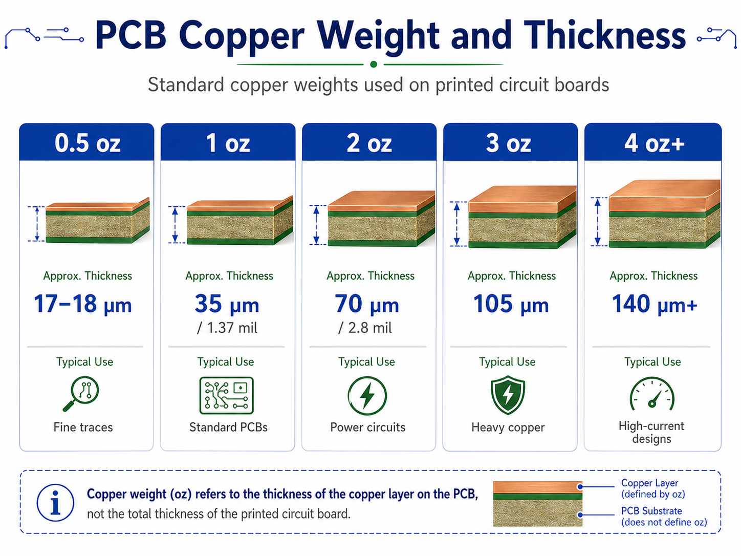
                Standard thickness ranges include 0.5–1 oz for low‑power consumer electronics, 1–3 oz for industrial and automotive use, and 3–10 oz for high‑power, aerospace, and heavy‑duty equipment.

                EBest engineers help you select the optimal copper thickness based on your current load, working environment, and industry standards to balance performance and reliability.

                Copper Plated PCB, https://www.bestpcbs.com/blog/2026/04/copper-plated-pcb/

                How to Improve Copper Plated PCBs Reliability in Medical & Aerospace?

                Medical and aerospace electronics require zero-failure performance under extreme temperatures, vibration, and long-term operation. Copper plated PCB reliability must be engineered at the material, process, and design levels to meet these strict demands.

                • Use high-TG and low-CTE base materials to minimize thermal expansion and avoid layer separation or via cracking in repeated temperature cycles.
                • Maintain strict copper plating thickness to meet IPC Class 3 standards, ensuring full, uniform coverage in high aspect ratio vias with no voids or weak points.
                • Adopt thermal relief structures and reinforced via/pad designs to reduce stress concentration and improve resistance to shock and vibration.
                • Apply enhanced surface treatment and bonding processes to maintain stable conductivity and prevent oxidation, peeling, or delamination.
                • Perform full reliability validation including thermal shock, temperature cycling, humidity testing, and mechanical vibration to ensure long-term stability.
                • Follow ISO 13485 for medical devices and AS9100D for aerospace systems to ensure full traceability, consistency, and compliance.
                • Optimize layer stack and copper distribution to balance internal stress and avoid board warping or deformation in critical applications.

                What Are Common Defects in Copper Plated PCB Manufacturing?

                Copper plated PCB defects directly affect conductivity, reliability, and assembly yield. Most issues come from uneven plating, insufficient pretreatment, poor process control, or unbalanced design.

                • Uneven copper plating thickness across traces, pads, and vias, leading to inconsistent conductivity and localized overheating.
                • Voids or incomplete plating inside through holes and vias, causing open circuits or weak, unstable electrical connections.
                • Poor adhesion between copper plating and the base material, resulting in blistering, peeling, or delamination during use.
                • Rough or nodular copper surface that reduces solderability and increases the risk of assembly defects.
                • Board warpage or twisting caused by unbalanced copper layout, asymmetric lamination, or uneven plating stress.
                • Burning or discoloration in dense or thin circuit areas due to improper current control during plating.
                • Insufficient coverage on high-aspect-ratio vias, which reduces structural strength and leads to early field failure.

                How Does Copper Plated PCBs Enhance Thermal Management?

                Effective thermal control is critical for high-power and high-reliability electronics. Copper plated PCB greatly improves heat dissipation using the high thermal conductivity of copper.

                • Copper transfers heat rapidly from heat-generating components to the entire board surface, reducing localized overheating.
                • Thick, uniform copper layers spread heat evenly, eliminate hotspots, and lower the operating temperature of key components.
                • Plated vias and copper planes create efficient heat paths to heat sinks, chassis, or external cooling systems.
                • Higher copper thickness reduces thermal resistance between layers, boosting overall cooling efficiency in high-power devices.
                • Better thermal management reduces thermal fatigue, extending service life in industrial, medical, and aerospace environments.
                • Balanced copper distribution reduces thermal stress, protecting against trace cracking, board warping, and premature failure.
                Copper Plated PCB, https://www.bestpcbs.com/blog/2026/04/copper-plated-pcb/

                FAQs About Copper Plated PCB Board

                Q1: What is the main difference between copper plated PCB and standard PCB?
                A1: Copper plated PCB has reinforced plating layers for better conductivity, higher current capacity, improved heat dissipation, and stronger structural reliability.

                Q2: Which industries use copper plated PCB most widely?
                A2: Medical devices, aerospace systems, industrial equipment, automotive electronics, power supplies, and high‑frequency communication devices.

                Q3: What copper thickness is suitable for high‑current applications?
                A3: 3 oz to 10 oz or heavier copper plating is typically recommended for high‑current designs.

                Q4: Can you produce copper plated PCB for medical equipment?
                A4: Yes, we are ISO 13485 certified and support Class I to Class III medical devices.

                Q5: Do you support aerospace‑grade copper plated PCB?
                A5: Yes, we hold AS9100D and provide high‑reliability boards for aerospace and aviation systems.

                Q6: How fast can you deliver copper plated PCB prototypes?
                A6: We offer expedited services with delivery within 24 hours for urgent orders.

                Q7: What quality standards do you follow for copper plated PCB?
                A7: We follow IPC‑A‑600, IPC‑6012, plus IATF 16949, ISO 9001, ISO 13485, AS9100D, RoHS, REACH, and UL requirements.

                Q8: Can you manufacture heavy copper plated PCB?
                A8: Yes, we support thick copper, heavy copper, and high‑power circuit designs.

                Order Copper Plated PCB From EBest Today

                EBest provides full‑service solutions for copper plated PCB and copper plated PCB board, covering design, prototyping, mass production, and assembly. If you need high‑quality, reliable, and fast‑delivery copper plated PCB, please contact us via email: sales@bestpcbs.com to place your order.

                You may also like

                Thick Copper MCPCB: High Current for Automotive Power Modules

                April 10th, 2026

                Are you facing overheating, insufficient current capacity, and early failure with automotive thick copper MCPCB in high‑power vehicle systems?This article explains how automotive thick copper PCB solves thermal and reliability challenges in automotive power modules. EBest provides certified, high‑stability automotive thick copper PCB with fast delivery, consistent quality, and full support from prototype to mass production.

                Automotive thick copper PCB, https://www.bestpcbs.com/blog/2026/04/thick-copper-mcpcb/

                Why Choose EBest for Your Automotive Thick Copper MCPCB Manufacturer?

                EBest is your trusted partner for automotive thick copper MCPCB with proven quality, fast delivery, and professional support for vehicle power systems. We focus on real engineering value and stable supply to help your project succeed.

                • Automotive-grade quality & full traceability: Built under IATF 16949 controls, with zero-defect targets and full documentation for OEM and Tier 1 compliance.
                • Extreme environment reliability: Designed for -40°C to +150°C, high vibration, and high current to avoid overheating and premature failure.
                • Fast prototype & mass production capability: 24-hour urgent prototype service + stable large‑volume delivery to keep your project on schedule.
                • High current & superior thermal performance: 3–12oz thick copper structure for efficient heat dissipation and stable high‑power operation.
                • Professional DFM & engineering support: Free design review to improve yield, lower risks, and optimize thermal and electrical performance.
                • Stable & secure supply chain: Reliable material sourcing and consistent production to eliminate delays and supply disruptions.
                • Full certification compliance: IATF 16949, ISO 9001, ISO 13485, AS9100D, RoHS, REACH, UL for global automotive standards.
                • Customizable solutions: Flexible layer stack-up, surface finish, and thickness to match your exact power module requirements.

                Our Quality Certifications for Automotive Thick Copper MCPCB

                • IATF 16949: Full automotive production process control, eliminates quality risks and ensures full traceability for vehicle applications.
                • ISO 9001:2015: Stable and repeatable manufacturing processes to keep quality consistent across every batch.
                • ISO 13485:2016: High‑reliability controls for safety‑critical automotive systems that demand zero failure.
                • AS9100D: Ensures stable performance under extreme temperature, vibration, and mechanical shock.
                • REACH & RoHS: Eco‑friendly materials that meet global automotive environmental requirements.
                • UL: Safety certification for high‑voltage and high‑current power modules in vehicles.
                Thick Copper MCPCB, https://www.bestpcbs.com/blog/2026/04/thick-copper-mcpcb/

                What Pain Points Does Automotive Thick Copper MCPCB Solve?

                High-power automotive systems often suffer from critical failures caused by poor heat dissipation, insufficient current handling, and unstable material performance. EBest’s automotive thick copper MCPCB directly resolves these pain points with targeted design and manufacturing solutions.

                Pain point 1: Overheating & thermal runaway in power modules.
                Solution 1: 3–12oz thick copper layers + high-thermal-conductivity substrates for fast heat dissipation.

                Pain point 2: Insufficient current carrying capacity.
                Solution 2: Heavy copper structure supports ultra-high current loads without trace burning or voltage drop.

                Pain point 3: Board delamination under high temperature & vibration.
                Solution 3: High-Tg materials + controlled lamination process for strong layer adhesion and stability.

                Pain point 4: Failure in harsh -40°C to +150°C environments.
                Solution 4: Automotive-grade materials engineered to withstand extreme temperatures and thermal cycling.

                Pain point 5: Poor reliability under vehicle vibration & shock.
                Solution 5: Robust mechanical structure and reinforced bonding to resist long-term vibration stress.

                Pain point 6: Non-compliance with automotive quality standards.
                Solution 6: Full IATF 16949, ISO, UL, RoHS certifications for direct OEM & Tier 1 approval.

                Pain point 7: Inconsistent quality in mass production.
                Solution 7: Automated production, full traceability, and strict testing to ensure batch-to-batch consistency.

                Pain point 8: Long lead times delaying project launch.
                Solution 8: 24-hour rapid prototyping + stable mass production to speed up development cycles.

                What Is an Automotive Thick Copper MCPCB?

                An automotive thick copper MCPCB is a heavy‑copper circuit board engineered specifically for vehicle power systems.It uses 3oz to 12oz copper layers to safely carry high current and efficiently dissipate heat. Built to withstand -40°C to +150°C, high vibration, humidity, and thermal stress, it delivers long‑term reliability. This type of PCB is essential for high‑power automotive applications where standard boards cannot perform.

                Thick Copper MCPCB, https://www.bestpcbs.com/blog/2026/04/thick-copper-mcpcb/

                Why Use Thick Copper MCPCBs in Automotive Power Modules?

                Thick copper greatly reduces electrical resistance and lowers IÂČR power loss in high‑current circuits. Superior thermal management prevents hotspots and extends the service life of power components. High mechanical strength resists vibration and thermal stress in harsh vehicle environments.

                It is widely used in EV inverters, battery management systems, on-board chargers, and high‑power distribution units.Without thick copper technology, high‑power automotive systems face overheating and reliability risks.

                How Does Thick Copper Improve Thermal Performance in Vehicles?

                Thick copper greatly boosts thermal performance in automotive power systems because copper is one of the most thermally conductive materials used in PCBs. Compared with standard thin-copper boards, automotive thick copper PCB quickly moves heat away from heat-generating components, preventing dangerous hotspots.

                In high-power vehicle applications such as EV inverters and on-board chargers, components release large amounts of heat during operation. Thick copper layers spread this heat evenly across the entire board surface instead of trapping it in small areas. This even distribution lowers peak temperatures and stabilizes the whole module.

                When combined with metal core or high-Tg substrates, thick copper forms an efficient thermal pathway that reduces overall thermal resistance dramatically. Lower thermal resistance means cooler running components, longer service life, higher reliability, and safer operation in harsh automotive environments.

                What Key Specifications Matter for Automotive Thick Copper MCPCB?

                SpecificationStandard Value
                Copper Weight3–12 oz (105–420 ÎŒm)
                Operating Temperature Range-40°C to +150°C
                High Tg Substrate≄170°C
                Current Carrying CapacityUp to 150A per module
                Withstand Voltage≄1000V
                Thermal ConductivityHigh (optimized for MCPCB)
                Surface FinishENIG / Immersion Silver
                Layer Structure1–12 layers, symmetric stack
                CertificationIATF 16949, UL, RoHS, ISO

                How to Design DFM‑Friendly Automotive Thick Copper MCPCB?

                DFM-friendly design directly improves yield, lowers cost, and enhances reliability for automotive thick copper MCPCB. These practical rules help avoid manufacturing defects and ensure stable mass production.

                • Use symmetric layer stacking to avoid warping and stress in high-temperature processes.
                • Maintain balanced copper distribution across the board to prevent uneven heating and bending.
                • Keep safe trace spacing and creepage distance for high-voltage automotive safety standards.
                • Add thermal relief structures and buffer layers to lower stress from CTE mismatch.
                • Avoid ultra-small features that thick-copper processes cannot stably produce.
                • Use compatible high-Tg materials matched with thick copper for better lamination and adhesion.
                • Reserve sufficient space for test points to support electrical and reliability verification.

                How Is Automotive Thick Copper PCB Used in Real Vehicle Systems?

                Here are automotive thick copper PCB used in real vehicle systems:

                • EV Inverters: Handles 800V high power without overheating and supports stable energy conversion.
                • Battery Management Systems (BMS): Ensures stable current paths and accurate cell monitoring.
                • On-Board Chargers (OBC): Manages high‑speed charging current safely and efficiently.
                • ADAS Power Units: Maintains consistent performance under vibration and temperature changes.
                • One of our customers reduced module temperature by 35°C and improved system efficiency by 12% using our automotive thick copper PCB.

                How to Prevent Delamination & Copper Separation?

                Delamination and copper separation are common failures in automotive thick copper PCB under high heat and thermal cycling. These proven methods effectively strengthen bonding, reduce internal stress, and ensure long-term stability.

                • Use graded-temperature lamination to reduce internal stress between layers.
                • Add thermal buffer layers to balance CTE differences and avoid material separation.
                • Select matched CTE high-Tg substrates to minimize expansion mismatch.
                • Pre-bake boards before assembly to remove moisture and prevent blistering.
                • Maintain uniform copper distribution to avoid uneven heating and warping.
                • Use strict process control and automated inspection to ensure bonding quality.
                Thick Copper MCPCB, https://www.bestpcbs.com/blog/2026/04/thick-copper-mcpcb/

                What Testing Ensures Reliability for Automotive Thick Copper PCB?

                Reliability testing is critical to validate automotive thick copper PCB performance under real vehicle conditions. These tests confirm long-term stability and meet strict automotive quality requirements.

                • Thermal cycling test (-40°C to 125°C) to verify stability under extreme temperature changes.
                • Vibration test (5G, 10–2000Hz) to simulate vehicle driving conditions and resist mechanical stress.
                • High-voltage breakdown test to ensure safety for high-power EV systems.
                • Solderability and adhesion test to confirm strong bonding during assembly.
                • Current-carrying endurance test to validate stable performance under long-term high load.
                • Thermal shock test to check material strength and avoid delamination or cracking.
                • Automated optical and electrical testing to ensure 100% qualification before shipment.

                FAQs About Automotive Thick Copper PCB

                Q1: What copper thickness do I need for automotive power modules?
                A1: For 50–100A applications, choose 3–5oz; for >100A high‑power systems, use 6–12oz automotive thick copper PCB.

                Q2: Can thick copper PCBs be made as multilayer boards?
                A2: Yes, multilayer automotive thick copper PCB is widely used; symmetric stacking prevents warping and ensures stability.

                Q3: Do you support quick‑turn prototype orders?
                A3: Yes, urgent prototypes can be shipped within 24 hours to support your fast development schedule.

                Q4: Are these boards compatible with SiC and GaN components?
                A4: Yes, our automotive thick copper PCB works excellently with high‑heat wide‑bandgap semiconductor devices.

                Q5: What is the operating temperature range for automotive use?
                A5: Our automotive thick copper MCPCB supports -40°C to +150°C, ideal for under‑hood and high‑power environments.

                Q6: Can you provide IATF 16949 compliance documents?
                A6: Yes, we provide complete PPAP and quality documentation for all automotive projects.

                Get Your Automotive Thick Copper PCB from EBest Today

                EBest provides high‑reliability automotive thick copper PCB with fast prototype delivery and exclusive mass‑production support. We offer stable quality, short lead times, and full technical backing for your automotive projects. Contact us now to place your order: sales@bestpcbs.com — EBest is your trusted partner for automotive thick copper PCB.

                You may also like

                FabricaciĂłn De PCB Costa Rica | Calidad Garantizada

                April 9th, 2026

                Are you tired of unreliable lead times, inconsistent quality, and hidden risks during fabricación de PCB that derail your prototypes and production schedules? In this guide, we break down the real challenges in diseño y fabricación de PCB, explain el proceso de fabricación de PCB in clear steps, compare top local suppliers, and show how EBest delivers stable, certified, and fast fabricación de PCB a medida with free DFM analysis and flexible support. By the end, you will know exactly how to choose a trusted PCB partner and why EBest is the top choice for reliable fabricación de PCB in Costa Rica and globally.

                FabricaciĂłn De PCB Costa Rica, https://www.bestpcbs.com/blog/2026/04/fabricacion-de-pcb-costa-rica/

                Why Choose EBest for Your FabricaciĂłn de PCB Needs?

                When you need professional and stable fabricaciĂłn de PCB, EBest Circuit is your best choice. Here are why choose us for your fabricaciĂłn de PCB needs:

                • Ultra‑fast lead time: Urgent prototype orders ship within 24 hours to keep your project on track.
                • Consistent high quality: Full process inspection and zero‑defect control for reliable end products.
                • Complete industry certifications: IATF 16949, ISO 9001, ISO 13485, AS9100D, REACH, RoHS, UL for global market access.
                • Free DFM analysis for every project: Fix design risks early and avoid costly reworks.
                • Flexible MOQ for prototypes: Support small‑batch trials with no unnecessary barriers.
                • Full customization: Expert fabricaciĂłn de PCB a medida for any layer, material, or performance requirement.
                • One‑stop service: Covering diseño y fabricaciĂłn de PCB, assembly, components, and testing.
                • Stable mass production capacity: Consistent quality between samples and volume orders.
                • Strong engineering support: In‑house technical team to solve complex design and production issues.
                • High‑precision capabilities: HDI, high‑TG, heavy copper, high‑frequency, and rigid‑flex PCBs supported.
                • Full traceability: Material and production records for medical, automotive, and aerospace projects.
                • Global logistics support: Reliable delivery to Costa Rica and worldwide destinations.

                We put your project success first with professional fabricaciĂłn de PCB solutions you can trust.

                Our Comprehensive Diseño y Fabricación de PCB Services

                EBest provides full‑cycle diseño y fabricaciĂłn de PCB for global customers.

                • PCB Design: Layout, impedance control, and schematic support.
                • PCB Prototype: Rapid small‑batch production.
                • Mass Production: Stable high‑volume manufacturing.
                • Component Sourcing: Authentic components with full traceability.
                • PCB Assembly: SMT, through‑hole, and functional testing.

                All services include customization and free DFM reports for design optimization.

                FabricaciĂłn De PCB Costa Rica, https://www.bestpcbs.com/blog/2026/04/fabricacion-de-pcb-costa-rica/

                Quality Certifications for Reliable FabricaciĂłn de PCB

                Our certifications guarantee compliant and trustworthy fabricaciĂłn de PCB.

                • IATF 16949: Automotive electronics standard.
                • ISO 9001:2015: Quality management system.
                • ISO 13485:2016: Medical device quality system.
                • AS9100D: Aerospace and high‑reliability standard.
                • REACH & RoHS: Environmental compliance.
                • UL: International safety certification.

                These certifications meet global industry and market requirements.

                Our Production Capabilities for FabricaciĂłn de PCB a Medida

                CapabilitySpecification
                Monthly Capacity260,000 ftÂČ / 28,900 mÂČ
                Board TypesFR4, metal core, ceramic, flex, rigid‑flex, RF, high‑frequency
                Layer Count1–78 layers, HDI supported
                Special FeaturesHeavy copper, high TG, ultra‑thin, impedance control, IC substrates
                Quick Turn24‑hour expedite service for urgent orders

                Common Challenges in El Proceso de FabricaciĂłn de PCB & How We Solve Them

                Engineering, design, and procurement teams frequently face costly, time‑consuming obstacles during el proceso de fabricación de PCB. We deliver clear, actionable solutions to keep your project on track.

                • Designs that fail manufacturing validation: Our dedicated engineering team provides free DFM analysis to identify and correct layout, spacing, impedance, and material conflicts before production, eliminating reworks and delays.
                • Excessively long lead times for prototype development: We offer dedicated rapid prototype lines and 24‑hour expedite services to support urgent testing, product launches, and time‑sensitive development cycles.
                • Inconsistent quality between prototypes and mass production: We use identical materials, production lines, and quality standards for both samples and mass production, ensuring stable performance and full compatibility at any volume.
                • Lack of certifications for medical, automotive, and aerospace use: Our facilities hold IATF 16949, ISO 13485, AS9100D, UL, RoHS, and REACH certifications, supporting regulated industries with full compliance and audit-ready documentation.
                • Inflexible order requirements for small-batch R&D projects: We support flexible MOQ for prototypes and pre-production runs, letting you validate designs and test markets without high upfront commitments or waste.
                • Unclear communication and slow technical support: Our in-house engineering team provides direct, timely technical support throughout design, production, and delivery, keeping you informed and resolving issues quickly.

                When you need consistent, professional fabricaciĂłn de PCB, EBest delivers proven, end-to-end solutions tailored to your needs.

                Top 10 FabricaciĂłn de PCB Manufacturers in Costa Rica

                Company NameMain Products & ServicesProduction ProcessLead Time
                EBest CircuitFull diseño y fabricaciĂłn de PCB, HDI, high-frequency, rigid-flex, fabricaciĂłn de PCB a medida, assembly1–78 layers, HDI, heavy copper, high TG, RF, MCPCB, ceramicPrototype: 2–5 days; Urgent: 24 hours; Mass: 7–10 days
                Electrónica PCB Costa RicaStandard FR4 PCB, prototypes, small-batch production1–4 layer standard FR4Prototype: 5–7 days; Mass: 10–15 days
                PCB Solutions CRSingle/double-sided PCB, low-volume assembly1–2 layer basic rigid PCBPrototype: 6–8 days; Mass: 12–18 days
                TechCircuit CRRigid PCBs for consumer electronics1–4 layer standard PCBPrototype: 5–7 days; Mass: 10–15 days
                CentroamĂ©rica PCBSimple rigid boards, local assembly1–2 layer basic PCBPrototype: 7–10 days; Mass: 15–20 days
                PCB Prototipos CRFast prototypes, basic 1–2 layer boards1–2 layer simple PCBPrototype: 3–5 days; Mass: Not supported
                Electronic Manufacturing CRThrough-hole assembly, basic rigid PCBs1–4 layer standard PCBPrototype: 6–9 days; Mass: 12–18 days
                PCB Industrial CRIndustrial control boards, standard rigid PCB1–4 layer industrial PCBPrototype: 5–8 days; Mass: 10–16 days
                PCB MĂ©dico CRBasic medical PCBs, simple rigid boards1–4 layer medical grade PCBPrototype: 7–10 days; Mass: 14–20 days
                PCB Auto CRBasic automotive boards, standard rigid PCB1–4 layer automotive PCBPrototype: 6–9 days; Mass: 12–18 days

                How Does El Proceso de FabricaciĂłn de PCB Work Step by Step?

                El proceso de fabricaciĂłn de PCB follows a strict, repeatable engineering workflow to ensure reliability and consistency for every custom board. Below is the complete, easy-to-understand production flow.

                1. Receive design files: Gerber data, BOM, drill files, and stack-up details.
                2. Perform free DFM analysis to check for design errors, spacing, impedance, and manufacturability.
                3. Confirm materials and specifications: Copper thickness, substrate type, surface finish, and layer count.
                4. Laminate core and prepreg materials under high temperature and pressure.
                5. Image circuit patterns onto the inner layers using dry film and exposure.
                6. Etch to remove excess copper and form the circuit pattern.
                7. Optical inspection (AOI) to detect defects in inner layers.
                8. Layer stacking and lamination for multilayer PCBs.
                9. CNC drilling for vias and through-holes.
                10. Electroless copper plating and electroplating to build conductive paths.
                11. Outer layer imaging, etching, and tin plating.
                12. Solder mask application for insulation and protection.
                13. Surface finish treatment: ENIG, HASL, immersion silver, or other required finishes.
                14. Silkscreen printing for labels, logos, and component indicators.
                15. Electrical testing (ET) to check open/short circuits.
                16. Final visual inspection and quality verification.
                17. Packaging, labeling, and shipment according to customer requirements.
                FabricaciĂłn De PCB Costa Rica, https://www.bestpcbs.com/blog/2026/04/fabricacion-de-pcb-costa-rica/

                Industry Applications for High‑Performance PCB Solutions

                We deliver targeted fabricación de PCB and fabricación de PCB a medida for four high‑demand industries, with fully customized designs, certified quality, and optimized performance for real‑world use.

                Automotive Electronics

                We provide fabricaciĂłn de PCB a medida including heavy copper PCBs and metal core PCBs (MCPCB) for electric vehicle controllers, battery management systems (BMS), and automotive sensors.

                All boards are built under IATF 16949 standards, with stable performance in high‑temperature and vibration environments. Custom layer counts, materials, and thermal designs are fully supported to meet strict automotive requirements.

                Medical Devices

                Our fabricación de PCB a medida delivers rigid‑flex PCBs, ultra‑thin PCBs, and high‑precision boards for patient monitors, diagnostic equipment, and portable medical devices.

                Certified to ISO 13485, these boards offer reliable signal transmission, long‑term stability, and full traceability.Custom specifications ensure compatibility with strict medical regulatory and safety demands.

                Industrial Control & Automation

                We offer fabricaciĂłn de PCB a medida with high TG, multilayer, and heavy copper structures for PLCs, industrial drives, robotics, and automation control systems.

                These PCBs resist high temperatures, electrical interference, and long‑term continuous operation.Custom designs improve stability and extend service life in harsh industrial environments.

                Communications & Servers

                Our fabricación de PCB a medida provides high‑speed, impedance‑controlled, and high‑frequency PCBs for 5G equipment, data center servers, routers, and communication base stations.

                These boards ensure stable signal transmission, low loss, and reliable performance for high‑speed data processing. Full customization supports complex stack‑up, impedance control, and high‑density layout requirements.

                All industry solutions include free DFM analysis and full engineering support to bring your custom PCB designs.

                How to Select the Best Partner for Diseño y Fabricación de PCB?

                Choosing a reliable provider for diseño y fabricación de PCB directly affects product quality, lead time, and project success. Use these key criteria to evaluate and select your ideal partner.

                • Verify industry‑relevant certifications: Check for IATF 16949 (automotive), ISO 13485 (medical), AS9100D (aerospace), ISO 9001, RoHS, REACH, and UL to ensure compliance and quality stability.
                • Confirm comprehensive technical and manufacturing capabilities: Ensure the supplier supports HDI, high‑TG, heavy copper, rigid‑flex, high‑frequency, and fabricaciĂłn de PCB a medida to match your design requirements.
                • Check for professional DFM and engineering support: A qualified partner must provide free DFM analysis to optimize designs, reduce risks, and prevent costly reworks during production.
                • Evaluate lead time and quick‑turn services: Reliable suppliers offer fast prototype turnaround and 24‑hour expedite services to support urgent development and product launches.
                • Review quality control and testing systems: Confirm full process inspection, AOI, electrical testing, and traceability systems to ensure consistent quality between prototypes and mass production.
                • Check one‑stop service coverage: Prefer suppliers offering full diseño y fabricaciĂłn de PCB, component sourcing, assembly, and testing to simplify management and reduce coordination risks.
                • Evaluate MOQ flexibility for prototypes and small batches: A customer‑focused manufacturer supports flexible MOQ for R&D and pre‑production trials without unnecessary restrictions.
                • Review real customer cases and industry experience: Choose partners with successful applications in your target industry (automotive, medical, industrial, communications) for better technical matching.
                • Check communication and technical support efficiency: Direct engineering support and responsive service help resolve issues quickly and keep projects on schedule.
                • Confirm stable supply chain and material traceability: Ensure authentic raw materials, full batch traceability, and stable supply to avoid production delays or quality risks.
                • Evaluate global logistics and after‑sales support: Reliable delivery, packaging, and after‑sales service ensure smooth receipt and support for your fabricaciĂłn de PCB projects.
                FabricaciĂłn De PCB Costa Rica, https://www.bestpcbs.com/blog/2026/04/fabricacion-de-pcb-costa-rica/

                FAQ: Preguntas Frecuentes sobre FabricaciĂłn de PCB en Costa Rica

                Q1: What is the typical lead time for fabricaciĂłn de PCB?
                A1: Standard prototypes: 3–5 days; urgent orders: 24 hours.

                Q2: Do you offer fabricaciĂłn de PCB a medida?
                A2: Yes, we fully support custom layers, materials, thickness, impedance, and special performance requirements.

                Q3: Is free DFM analysis included?
                A3: Yes, free DFM is provided for all orders to optimize design and avoid production risks.

                Q4: Can you produce HDI and high‑frequency PCBs?
                A4: Yes, HDI, high‑TG, heavy copper, RF, and high‑frequency boards are all available.

                Q5: Do you provide PCB assembly services?
                A5: Yes, we offer one‑stop diseño y fabricaciĂłn de PCB + assembly + testing.

                Contact EBest for Your FabricaciĂłn de PCB Project

                EBest provides professional fabricación de PCB, diseño y fabricación de PCB, and fabricación de PCB a medida with certified quality and fast delivery.We support customization and include free DFM reports for every project. Contact us now: sales@bestpcbs.com to get a free quote for your project!

                You may also like

                Top PCB Manufacturer in Cambodia: Custom ISO‑Certified PCB Solutions for Global Buyers

                April 1st, 2026

                When you search for a professional, reliable, and certified PCB manufacturer in Cambodia, you need a partner that delivers consistent quality, on‑time delivery, full regulatory compliance, and end‑to‑end manufacturing support. Established in 2006, EBest Circuit (Best Technology) is a trusted PCB manufacturer in Cambodia with over 20 years of experience serving global buyers in automotive, medical, aerospace, industrial, consumer electronics, and communications markets. We specialize in custom PCB manufacturing, rapid prototyping, mass production, and turnkey PCB assembly, helping engineering, procurement, and production teams reduce risks, accelerate product launches, and stabilize supply chains.

                PCB Manufacturer in Cambodia, https://www.bestpcbs.com/blog/2026/04/pcb-manufacturer-in-cambodia/

                Why Choose EBest as Your Trusted PCB Manufacturer in Cambodia?

                When you partner with EBest, you gain more than a supplier, you get a dedicated manufacturing partner focused on your success. We prioritize your lead times, quality, compliance, and total project efficiency.

                • On-time delivery guaranteed: Expedited orders ship in 24 hours; mass production strictly follows committed schedules to keep your project on track.
                • Stable, repeatable quality: Full-process inspection and automated production minimize defects and ensure consistency in every batch.
                • Complete global certifications: IATF 16949, ISO 9001, ISO 13485, AS9100D, REACH, RoHS, UL, fully compliant for automotive, medical, aerospace, and industrial markets.
                • Customization & free support: Custom PCB design & manufacturing with free DFM analysis to optimize your design, lower failure rates, and avoid production delays.
                • Flexible MOQ & service: Low minimum order quantity for prototypes; personalized support for small-batch R&D and large-scale mass production.
                • Full component & assembly support: One-stop service eliminates coordination hassle and shortens your overall supply cycle.

                Our Full-Service PCB Solutions as a Leading PCB Manufacturer in Cambodia

                As a premier PCB manufacturer in Cambodia, EBest provides end-to-end support from design to final delivery.

                • PCB Design: Professional engineering support for schematic review, layout optimization, impedance control, high‑speed design, and manufacturability improvement.
                • PCB Prototype: Rapid small‑batch prototyping to verify design performance, form, fit, and function before mass production. Ideal for R&D, testing, and product validation.
                • Mass Production: Stable high‑volume manufacturing with automated production lines, strict process control, and consistent quality for large‑scale market deployment.
                • Component Sourcing: Global reliable component supply chain with 100% genuine parts, full traceability, and alternative component support to avoid supply shortages.
                • PCB Assembly: Complete turnkey PCBA services including SMT, DIP, mixed assembly, potting, conformal coating, and functional testing for finished electronic products.
                 PCB Manufacturer in Cambodia, https://www.bestpcbs.com/blog/2026/04/pcb-manufacturer-in-cambodia/

                Our Authoritative Quality Certifications for Cambodia PCB Manufacturing Orders

                Certifications are not just badges, they are your guarantee of compliance, safety, and reliability. EBest holds industry-leading certifications:

                • IATF 16949 – Automotive Electronics Quality Management System
                • ISO 9001:2015 – International Quality Management System
                • ISO 13485:2016 – Medical Device Quality Management System
                • AS9100D – Aerospace Quality Management System
                • REACH – EU Chemical Substance Compliance
                • RoHS – Hazardous Substance Restriction Compliance
                • UL – Safety Certification for Global Market Access

                These certifications let you enter global markets with confidence and meet strict customer audit requirements.

                PCB Manufacturing Capacity & Advanced Process Capabilities

                ParameterDetailed Specification
                Monthly Production Capacity260,000 ftÂČ (28,900 mÂČ)
                Unique Board Types1,000+ different board versions
                Layer Count1–30 layers
                Base MaterialsFR4, Metal Core (MCPCB), Ceramic, Flex, Rigid‑Flex, High Frequency, High TG
                Minimum Track Width / Space3 mil (0.075 mm)
                Minimum Drill Hole Size0.15 mm
                Surface FinishesHASL, Lead‑Free HASL, ENIG, Immersion Silver, Immersion Tin, OSP
                Board Thickness Range0.2 mm – 6.0 mm
                Copper Weight0.5 oz – 6 oz (Heavy Copper supported)
                Prototype Lead Time24 hours – 5 days
                Mass Production Lead Time7 – 15 days
                Special CapabilitiesHDI, High‑TG, Impedance Control, High Speed, Heavy Copper, Ultra‑Thin, Busbar, IC Substrate, RF Microwave

                Which Industries in Cambodia Has EBest Served?

                EBest provides professional custom PCB and PCB assembly solutions for high‑growth industries that demand strict quality, reliability, and compliance. We focus on four core high‑demand sectors:

                Automotive Electronics PCB Solutions

                • Applications: Automotive lighting, engine sensors, body control modules, battery management systems (BMS), in‑vehicle infotainment.
                • Key Products: Metal Core PCBs, heavy copper PCBs, high‑TG PCBs.
                • Advantages: High temperature resistance, vibration resistance, long‑term stability, IATF 16949 certified.

                Industrial Control & Automation PCB Solutions

                • Applications: PLC controllers, servo drives, industrial sensors, robotics, automation equipment.
                • Key Products: Multilayer PCBs, heavy copper PCBs, impedance control PCBs, high‑speed PCBs.
                • Advantages: 24/7 stable operation, strong anti‑interference, high reliability for harsh industrial environments.

                Medical Electronics PCB Solutions

                • Applications: Diagnostic equipment, patient monitors, therapeutic devices, portable medical instruments.
                • Key Products: ISO 13485 certified PCBs, ultra‑thin PCBs, HDI PCBs.
                • Advantages: High reliability, full material traceability, strict cleanliness, medical regulatory compliance.

                Consumer Electronics PCB Solutions

                • Applications: Smartphones, wearables, tablets, smart home devices, portable electronics.
                • Key Products: HDI PCBs, ultra‑thin PCBs, rigid‑flex PCBs.
                • Advantages: High‑density layout, compact size, lightweight, fast prototyping for rapid product development.

                How EBest Solves Your Most Critical PCB Sourcing Challenges?

                Many engineering and procurement teams face consistent challenges when working with a PCB manufacturer in Cambodia, including delayed deliveries, unstable quality, insufficient certifications, weak technical support, unexpected production failures, and high redesign costs. EBest eliminates these pain points with structured, reliable solutions:

                • We deliver predictable, guaranteed lead times so your project stays on schedule.
                • Our full inspection system reduces failure rates and minimizes after‑sales issues.
                • Complete international certifications ensure full regulatory compliance.
                • Free DFM analysis identifies design risks early and lowers total production cost.
                • 20+ years of manufacturing experience enables us to handle complex, high‑precision boards.
                • Customized manufacturing supports your unique industry, application, and performance needs.
                • Integrated one‑stop service reduces supply chain complexity and coordination risk.

                When you partner with EBest, you gain long‑term stability, efficiency, and complete peace of mind for every project.

                Top 10 PCB Manufacturers in Cambodia in 2026

                Company NameCertificationsMain Products & ServicesProcess CapabilityLead Time
                EBest CircuitISO 9001, ISO 13485, IATF 16949, AS9100D, RoHS, ULFR4, HDI, MCPCB, Ceramic, Flex/Rigid-Flex; Prototype & Mass Production; Full PCB Assembly1–30 layers, 0.15 mm min hole, heavy copper, high frequency, impedance control, RFPrototype: 24h–5d; Mass: 7–15d
                Cambodian PCB TechISO 9001, RoHSSingle/double-sided, multilayer FR4 PCB; small-batch SMT assembly1–8 layers, standard DFM supportPrototype: 5–7d; Mass: 12–20d
                Mekong PCB ManufacturingISO 9001Standard rigid PCBs, quick prototypes, basic assembly1–6 layers, standard materialsPrototype: 4–6d; Mass: 10–18d
                SEA Circuit SolutionsISO 9001, RoHSMultilayer PCB, LED MCPCB, industrial control boards1–12 layers, metal core supportedPrototype: 5–7d; Mass: 12–20d
                Angkor PCB AssemblyISO 9001PCB fabrication, low-volume assembly, component sourcing1–8 layers, basic SMTPrototype: 5–8d; Mass: 14–22d
                Phnom Penh PCB FactoryRoHSSingle/double-sided PCB, consumer electronics1–4 layers, standard finishPrototype: 4–6d; Mass: 10–18d
                Indochina PCB Co., Ltd.ISO 9001Multilayer PCB, prototype service, quick turnaround1–10 layers, standard DFMPrototype: 4–7d; Mass: 12–20d
                Royal PCB ManufacturingISO 9001, RoHSFR4 PCB, MCPCB for lighting1–8 layers, thermal managementPrototype: 5–7d; Mass: 12–20d
                Golden PCB CambodiaRoHSBasic rigid PCB, consumer electronics, small batch1–4 layers, standard materialsPrototype: 5–8d; Mass: 14–22d
                Advance PCB TechISO 9001High-TG PCB, heavy copper, industrial & automotive1–12 layers, high temperature resistantPrototype: 5–7d; Mass: 12–20d

                How to Select a Reliable PCB Manufacturer in Cambodia?

                Choosing a reliable PCB manufacturer in Cambodia is critical for product quality and supply chain security. Use these professional, practical criteria to evaluate partners:

                • Verify complete, valid, and industry‑matched certifications (ISO 9001, IATF 16949, ISO 13485, AS9100D, UL, RoHS).
                • Confirm real process capabilities, including layer count, minimum hole size, impedance control, HDI, high frequency, and heavy copper.
                • Evaluate actual on‑time delivery performance, not just advertised lead time.
                • Check professional technical support, especially free DFM analysis and custom design capabilities.
                • Review full quality control systems and testing procedures.
                • Assess production scale, equipment level, and ability to support both prototypes and mass production.
                • Confirm one‑stop service capability to reduce supply chain complexity.

                EBest meets and exceeds all these standards, making us the most trusted choice for global buyers.

                PCB Manufacturer in Cambodia, https://www.bestpcbs.com/blog/2026/04/pcb-manufacturer-in-cambodia/

                How Fast Can I Get PCB Prototypes & Mass Production in Cambodia?

                Lead time directly affects your R&D progress and market launch. As a leading PCB manufacturer in Cambodia, EBest maintains industry‑leading turnaround while upholding strict quality standards.

                • Standard PCB Prototype: 3–5 days.
                • Expedited Emergency Prototype: 24 hours.
                • Standard Multilayer Mass Production: 7–15 days.
                • Complex HDI / High‑Frequency / Rigid‑Flex: 10–20 days.

                We balance speed, quality, and reliability to support your most aggressive project schedules.

                PCB Mass Production in Cambodia, https://www.bestpcbs.com/blog/2026/04/pcb-manufacturer-in-cambodia/

                FAQs About PCB Manufacturer in Cambodia

                Q1: Do you provide free DFM analysis for PCB designs?
                A1: Yes, EBest offers free DFM reports to optimize your design, avoid production risks, improve yield, and reduce manufacturing costs.

                Q2: Can you support fully custom PCB manufacturing?
                A2: Yes, we provide full custom PCB solutions including layer count, base material, surface finish, impedance control, HDI, high frequency, heavy copper, and rigid‑flex designs.

                Q3: What international certifications do you hold?
                A3: We hold IATF 16949, ISO 9001:2015, ISO 13485:2016, AS9100D, REACH, RoHS, and UL certifications.

                Q4: What is your minimum order quantity (MOQ) for prototypes?
                A4: We support low MOQ for prototype projects to accommodate R&D, testing, and startup development.

                Q5: How fast is your expedited PCB prototype service?
                A5: Our emergency expedited service supports shipping within 24 hours for urgent and critical projects.

                Q6: Do you offer full turnkey PCB assembly (PCBA) services?
                A6: Yes, we provide one‑stop PCB assembly including component sourcing, SMT, DIP, mixed assembly, conformal coating, and functional testing.

                Q7: Can you produce high‑frequency, HDI, and heavy copper PCBs?
                A7: Yes, we specialize in advanced PCB types including high‑frequency, HDI, heavy copper, rigid‑flex, high‑TG, and impedance‑controlled boards.

                Q8: Is full material traceability available for medical and automotive projects?
                A8: Yes, full material traceability is standard for medical, automotive, aerospace, and other high‑reliability applications.

                You may also like

                Custom PCB Manufacturer in Hong Kong, Rapid Prototyping Service

                March 30th, 2026

                Finding a reliable PCB manufacturer in Hong Kong can be challenging, especially when you need high-quality products, fast lead times, and customized solutions that meet industry standards. EBest Circuit, a leading PCB manufacturer in Hong Kong with over 20 years of experience, offers one-stop PCB solutions including design, prototyping, mass production, component sourcing, and assembly. We address common manufacturing challenges, deliver certified quality, and ensure timely delivery, making us the ideal partner for all your PCB needs in Hong Kong.

                PCB Manufacturer in Hong Kong, https://www.bestpcbs.com/blog/2026/03/pcb-manufacturer-in-hong-kong/

                Who is the Largest PCB Manufacturer in Hong Kong?

                Headquartered in Hong Kong, Kingboard Holdings Limited is the region’s largest manufacturer of printed circuit boards (PCBs). Established in 1988, the company operates over 60 manufacturing facilities across mainland China, Hong Kong, and Thailand, and has evolved into a global leader in the production of laminates and PCBs.

                Listed on the Stock Exchange of Hong Kong since 1993, Kingboard Holdings has also earned a place on Forbes’ list of the “Global 2000” companies, a testament to its profound market influence and robust financial strength. The company’s operational capabilities encompass a range of advanced technological products, including High-Density Interconnect (HDI) boards, specialized laminates tailored for the telecommunications and automotive sectors, and multi-layer PCBs featuring up to 50 layers.

                Furthermore, the company has obtained numerous international certifications, such as ISO 9001:2015 and ISO 14001:2015, as well as IPC standard certifications, thereby ensuring the highest standards of product quality and sustainable development. Driven by an unwavering commitment to technological innovation and a global strategic footprint, Kingboard Holdings serves a diverse spectrum of industries, ranging from consumer electronics to industrial applications—further solidifying its leadership position within Hong Kong’s PCB sector.

                Top 10 PCB Manufacturer in Hong Kong

                Company NameMain BusinessCore AdvantagePCB Process CapabilityLead Time
                EBest Circuit Co., LimitedPCB Design, Prototype, Mass Production, Component Sourcing, PCB Assembly20+ years experience, one-stop solutions, 24-hour expedited service, strict quality controlFR4/metal/ceramic/flexible PCB fabrication, HDI/impedance control, 28,900 ㎡ monthly capacity, 1000+ board types monthly24h for urgent orders; 3-7 days for prototypes; 10-15 days for mass production
                Estec GroupMulti-layer PCB, HDI, Flex and Rigid-Flex PCB ManufacturingHolistic quality management, IPC-A-600 compliance, advanced HDI technologyMulti-layer PCB (up to 24 layers), HDI with blind/buried vias, flex-rigid PCB lamination, precision etching4-8 days for prototypes; 12-20 days for mass production
                AetPCBHigh-precision PCB, Multi-layer PCB, HDI PCB ManufacturingTight tolerance control, 6-layer HDI PCB at 0.45mm thickness, ISO certificationHigh-precision etching (3mil line/space), 6-layer HDI fabrication, multi-layer PCB (up to 16 layers), flying probe testing5-7 days for prototypes; 15-22 days for mass production
                HT Circuits Ltd.Single-sided, Double-sided, Multi-layer PCB ManufacturingHigh production capacity (300,000 ㎡ monthly for single-sided), flexible order fulfillmentSingle/double-sided PCB mass fabrication, multi-layer PCB (up to 12 layers), lead-free soldering, automatic optical inspection (AOI)3-5 days for prototypes; 8-14 days for mass production
                AKM MeadvilleHDI PCB, High-volume PCB, MSAP Technology PCB ManufacturingISO/IATF certified, high-volume production, SIP pro technologyMSAP process for HDI, high-volume PCB fabrication, impedance control, laser drilling, automated assembly line6-9 days for prototypes; 14-20 days for mass production
                South-ElectronicPCB Prototyping, Multi-layer PCB, Flexible/HDI PCB, PCBA4,200 ㎡ facility, 8 advanced production lines, 99.2% yield ratePrototype to mass production integration, flexible PCB lamination, HDI fabrication, SMT placement (01005 packages)3 days for small batch prototypes; 7 days for large batch prototypes; 10-18 days for mass production
                OurPCB Hong KongPCB Manufacturing, PCB Assembly, Wire Harness ManufacturingOne-stop service, 50-layer PCB capability, ISO/UL certifiedMulti-layer PCB (up to 50 layers), HDI, rigid-flex PCB, IC substrate fabrication, RoHS-compliant processes2-6 days for prototypes; 10-16 days for mass production
                Leadsintec TechnologyPCB Manufacturing, PCBA, Enclosure SolutionsInternational compliance support, engineering expertise, global logisticsCustom PCB fabrication, impedance control, high-frequency PCB processing, precision drilling and etching4-7 days for prototypes; 12-18 days for mass production
                Hong Kong PCB Tech Ltd.Flexible PCB, Rigid-Flex PCB, Medical PCB ManufacturingMedical grade certification, flexible design expertise, high precisionFlexible/rigid-flex PCB lamination, medical-grade PCB fabrication, cleanroom processing, strict quality inspection7-10 days for prototypes; 18-25 days for mass production
                HK Electronics Circuit Co.Standard FR4 PCB, Metal-based PCB, RF PCB ManufacturingCost-effective solutions, fast turnaround, reliable logisticsFR4 PCB fabrication, metal-based (MCPCB) processing, RF PCB impedance control, batch production optimization3-6 days for prototypes; 10-15 days for mass production

                What Are Common Challenges of PCB Manufacturer in Hong Kong?

                When working with a Hong Kong PCB manufacturer, what key pain points and difficulties do we frequently encounter? Here are common challenges of PCB manufacturing in Hong Kong:

                • How to maintain consistent impedance control (50Ω/75Ω/100Ω) for high-speed designs, avoiding signal integrity issues that degrade performance?
                • Why do HDI/flexible PCB prototypes frequently miss deadlines, creating gaps between engineering timelines and manufacturer turnaround?
                • How to resolve design-spec mismatches (e.g., 3mil line width/space) that cause rework, delays, and increased costs?
                • How to mitigate component shortages or supply chain delays that disrupt PCBA and force last-minute redesigns?
                • How to sustain high yield rates (≄99%) for complex 16-layer boards without inflating production costs?
                • How to streamline compliance alignment (ISO 13485, IATF 16949) for medical/automotive orders, avoiding certification bottlenecks?
                • How to offset rising material costs (CCL, copper) that squeeze profit margins in low-margin segments?

                Why Choose EBest for PCB Manufacturer in Hong Kong

                Here are reasons why choose EBest for PCB manufacturer in Hong Kong:

                • Cost Optimization: Leverage bulk component sourcing and process automation to offset 20–30% material cost hikes, maintaining competitive pricing without sacrificing quality.
                • Design-Process Alignment: Pre-manufacturing DFM checks resolve 95% of spec mismatches upfront, cutting rework by 40% and accelerating time-to-market.
                • Stable Supply Chain: 2,000+ global supplier partnerships reduce component lead-time risk by 35%, ensuring consistent BOM availability.
                • Compliance Expertise: ISO 9001:2015, IATF 16949, ISO 13485, and AS9100D certifications eliminate export barriers for medical, automotive, and aerospace orders.
                • Predictable Lead Time: 24h urgent prototype support and 3–7 days standard turnaround, with 99% on-time delivery for Hong Kong orders.
                • Technical Agility: 20+ years of expertise in HDI, flexible, and high-speed designs, with continuous R&D to match AI/automotive industry trends.
                • One-Stop Efficiency: Integrate PCB fabrication, component sourcing, and PCBA under one vendor, reducing coordination costs by 25% and streamlining communication.
                Why Choose EBest for PCB Manufacturer in Hong Kong, https://www.bestpcbs.com/blog/2026/03/pcb-manufacturer-in-hong-kong/

                What Customization Options Can We Offer for Hong Kong PCB Manufacturing Orders?

                Below are customization options we offer for Hong Kong PCB manufacturing orders:

                • Board Type: FR4, metal-core (MCPCB), ceramic, single/double-sided, multi-layer (up to 50 layers), flexible, rigid-flex, high-frequency, and impedance-controlled designs.
                • Specifications: High TG (T g ≄180°C), heavy copper (up to 20oz), extra-thin (0.2mm), and IC substrate solutions for high-density applications.
                • Size & Thickness: Custom dimensions and thicknesses to fit compact designs, including ultra-thin flexible boards for medical wearables.
                • Surface Finish: HASL (lead-free), ENIG, immersion silver, OSP, and gold plating to balance performance and cost.
                • Design Support: DFM optimization to improve yield, reduce material waste, and lower production costs by up to 15%.
                • Volume Flexibility: From 1-piece prototypes to mass production (28,900 ㎡ monthly capacity), with no minimum order quantity for prototyping.
                What Customization Options Can We Offer for Hong Kong PCB Manufacturing Orders, https://www.bestpcbs.com/blog/2026/03/pcb-manufacturer-in-hong-kong/

                What Quality Certifications Do We Hold for Our Hong Kong PCB Orders?

                Here are our quality certifications for Hong Kong PCB manufacturing orders:

                • ISO 9001:2015: Global quality management system for consistent product reliability.
                • IATF 16949: Automotive-specific certification for high-reliability vehicle electronics.
                • ISO 13485:2016: Medical-grade compliance for sterile, biocompatible device PCBs.
                • AS9100D: Aerospace certification for mission-critical, high-durability applications.
                • UL: Safety certification for electrical product compliance in North American markets.
                • RoHS/REACH: Hazardous substance restrictions for EU and global export readiness.
                • IPC-A-610: Class 3 quality standards for high-precision, long-life electronic assemblies.

                Our Printed Circuit Board Manufacturing Capabilities

                ItemCapabilities
                Layer Count1 – 32 Layers
                Max Board Dimension2424″ (610610mm)
                Min Board Thickness0.15mm
                Max Board Thickness6.0mm – 8.0mm
                Copper ThicknessOuter Layer: 1oz~30oz, Inner Layer: 0.5oz~30oz
                Min Line Width/Line SpaceNormal: 4/4mil (0.10mm); HDI: 3/3mil (0.076mm)
                Min Hole DiameterNormal: 8mil (0.20mm); HDI: 4mil (0.10mm)
                Min Punch Hole Dia0.1″ (2.5mm)
                Min Hole Spacing12mil (0.3mm)
                Min PAD Ring(Single)3mil (0.075mm)
                PTH Wall ThicknessNormal: 0.59mil (15um); HDI: 0.48mil (12um)
                Min Solder PAD DiaNormal: 14mil (0.35mm); HDI: 10mil (0.25mm)
                Min Soldermask BridgeNormal: 8mil (0.2mm); HDI: 6mil (0.15mm)
                Min BAG PAD Margin5mil (0.125mm)
                PTH/NPTH Dia TolerancePTH: ±3mil (0.075mm); NPTH: ±2mil (0.05mm)
                Hole Position Deviation±2mil (0.05mm)
                Outline ToleranceCNC: ±6mil (0.15mm); Die Punch: ±4mil (0.1mm); Precision Die: ±2mil (0.05mm)
                Impedance ControlledValue>50ohm: ±10%; Value≀50ohm: ±5ohm
                Max Aspect Ratio0.334027778
                Surface TreatmentENIG, Flash Gold, Hard Gold Finger, Gold Plating(50mil), Gold finger, Selected Gold plating, ENEPIG, ENIPIG; HAL, HASL(LF), OSP, Silver Immersion, Tin Immersion
                Soldermask ColorGreen/White/Black/Yellow/Blue/Red

                Our Typical Lead Time for PCB Prototyping Orders for Hong Kong

                LayersNormal ServiceFastest Service
                17 Days24 H
                28 Days24 H
                410 Days48 H
                610 Days72 H
                812 Days72 H
                ≄10TBDTBD

                Case Study: Medical PCBs We Produced for Hong Kong Clients

                Project Background:

                A Hong Kong medical device firm supplying Western Europe needed flexible PCBs for gastroscope catheters. The boards required repeated bending without signal loss, strict ISO 13485 compliance, and a 7-day prototype delivery to meet their product launch timeline.

                Project Requirements:

                • Bending Durability: ≄10,000 cycles with no signal degradation.
                • Form Factor: 0.3mm thickness to fit narrow catheter spaces.
                • Compliance: ISO 13485:2016 certification for medical-grade production.
                • Speed: 7-day prototype delivery; 15-day mass production lead time.

                Project Challenges:

                • Designing flexible circuits that withstand repeated bending while maintaining signal integrity.
                • Aligning manufacturing processes with ISO 13485 documentation and traceability requirements.
                • Meeting the tight 7-day prototype window without compromising quality.

                Our Solutions

                • Material Optimization: Selected high-flex PI substrates with reinforced copper traces to resist fatigue.
                • Design Iteration: Collaborated on DFM to reduce thickness while maintaining structural integrity, ensuring 10,000+ bending cycles.
                • Compliance Alignment: Implemented ISO 13485-aligned traceability and inspection protocols for batch consistency.
                • Priority Scheduling: Dedicated production line for the order to meet the 7-day prototype deadline.

                Output Results

                • Delivered 50 ISO 13485-certified prototypes in 7 days, passing all quality and performance tests.
                • Achieved 99.5% yield in mass production, exceeding the client’s 99% target.
                • The final PCBs were integrated into gastroscope devices and launched successfully in Western Europe, with zero field failures to date.
                Medical PCBs We Produced for Hong Kong Clients, https://www.bestpcbs.com/blog/2026/03/pcb-manufacturer-in-hong-kong/

                FAQs About PCB Manufacturing in Hong Kong

                Q1: What file format do I need to provide for PCB manufacturing orders in Hong Kong?
                A1: We require PCB design files in Gerber RS-274X format (preferred), .pcb/.ddb (Protel, specify program version), or .brd (Eagle) format. Providing clear design files ensures accurate production and avoids delays.

                Q2: Is there a minimum order quantity (MOQ) for PCB prototyping in Hong Kong?
                A2: No, we have no MOQ requirement for PCB prototyping. We can handle small-batch orders (even 1 piece) to support your product development and testing needs, with the same fast lead times and quality standards.

                Q3: How can I ensure my PCB order meets international compliance standards for export from Hong Kong?
                A3: We hold all key certifications (IATF 16949, ISO 13485:2016, REACH, RoHS, etc.) to meet international standards. Our team will verify your compliance requirements upfront and provide certification documentation with your order to facilitate export.

                Q4: What is the smallest trace width and spacing you can manufacture for Hong Kong PCB orders?
                A4: We can produce trace widths and spacing as small as 3 mils. Our controlled etching process ensures accurate dimensions, even for tight-tolerance designs, which is ideal for high-density PCBs.

                Q5: How quickly will I receive a quotation for my Hong Kong PCB manufacturing order?
                A5: We guarantee a response to all quotation requests within 24 hours. Simply provide your design files and requirements, and our team will deliver a detailed, transparent quotation with no hidden fee.

                You may also like

                LED Downlight Aluminum PCB | High Thermal MCPCB for Recessed Lighting

                March 26th, 2026

                Why Choose EBest for Your LED Downlight Aluminum PCB?

                EBest is your first choice for high-performance LED Downlight Aluminum PCB, with core parameters designed to meet the strict demands of LED downlight applications. Our products feature thermal conductivity ranging from 1.0 to 4.0 W/m·K, copper thickness of 1oz-4oz, and operating temperature range of -50℃ to 100℃, ensuring stable performance in all scenarios.

                We offer customizable sizes, precise dimensional tolerance of ±0.01mm, and compatibility with SMD, BGA, and QFN components. For a reliable, long-lasting LED Downlight Aluminum PCB that boosts your product’s lifespan and efficiency, place your order with EBest today.

                LED Downlight Aluminum PCB | High Thermal MCPCB for Recessed Lighting

                Why Choose Us for LED Downlight Aluminum PCB?

                • Quality: Our LED Downlight Aluminum PCB undergoes 100% full inspection before delivery, with strict quality control throughout the production process, complying with global industry standards.
                • Delivery: With a monthly production capacity of 260,000 square feet, we offer expedited service—urgent LED Downlight Aluminum PCB orders can be shipped within 24 hours.
                • Service: We provide one-stop solutions, from custom design and component sourcing to assembly, with 24/7 technical support for all your LED Downlight Aluminum PCB needs.
                • Supply Chain: Our stable, integrated supply chain ensures a consistent raw material supply, avoiding delays and ensuring steady production of your LED Downlight Aluminum PCB.

                What Are the Key Advantages of LED Downlight Aluminum PCB Over FR-4 PCB?

                LED Downlight Aluminum PCB outperforms FR-4 PCB primarily in heat dissipation, which is critical for LED downlight longevity. An aluminum PCB’s thermal conductivity is 3-8 times higher than that of FR-4, preventing LED overheating and light decay.

                FeatureLED Downlight Aluminum PCBFR-4 PCB
                Thermal Conductivity (W/m·K)1.0-4.00.3-0.4
                Operating Temperature Range-50℃ to 100℃-40℃ to 85℃
                LED Lifespan ImpactExtends lifespan to over 100,000 hoursShortens lifespan due to poor heat dissipation
                Mechanical StrengthHigh hardness, strong load-bearing capacityGood toughness, easy to process but less durable

                How to Design LED Downlight Aluminum PCB for Optimal Heat Dissipation?

                Optimal heat dissipation for a LED Downlight Aluminum PCB starts with three key design steps: expand heat pads, add sufficient thermal vias, and use appropriate copper thickness.

                Key Design Tips for Heat Dissipation

                • 1. Enlarge heat pads: Extend LED pad areas to increase heat transfer, avoiding minimal pad sizes that trap heat.
                • 2. Add thermal vias: Use 0.3mm vias spaced 1.5mm apart, with plugging and copper cladding to form a 3D heat dissipation channel.
                • 3. Choose proper copper thickness: Use 2oz (70ÎŒm) copper for LEDs over 1W to enhance heat conduction efficiency.
                LED Downlight Aluminum PCB | High Thermal MCPCB for Recessed Lighting

                What Are the Most Commons with LED Downlight Aluminum PCB, and How Do We Solve Them?

                Many users face issues like poor heat dissipation, unstable performance, and delivery delays with LED Downlight Aluminum PCB. EBest addresses these with targeted, proven solutions.

                • How to Fix Poor Heat Dissipation in LED Downlight Aluminum PCB?

                Solution: We use high-quality aluminum substrates and optimize layout, adding thermal vias and enlarged heat pads to reduce junction temperature by 20-30℃, extending lifespan significantly.

                • How to Ensure Consistent Quality for LED Downlight Aluminum PCB?

                Solution: Real-time production monitoring, from raw material inspection to final testing, ensures 100% compliance with industry standards.

                • How to Avoid Long Delivery Times for LED Downlight Aluminum PCB?

                Solution: Our large production capacity and expedited service deliver standard orders in 3-5 days and urgent orders within 24 hours.

                • How to Simplify Customization for LED Downlight Aluminum PCB?

                Solution: Our R&D team provides personalized design support, tailoring size, copper thickness, and thermal parameters to your needs.

                What Industries Rely on LED Downlight Aluminum PCB? 4 Real-World Cases

                LED Downlight Aluminum PCB is widely used in industries that demand efficient, reliable lighting solutions. Below are four key industries and our successful cases.

                • 1. Residential Lighting

                Case: We supplied LED Downlight Aluminum PCB for a global residential lighting brand, reducing LED light decay by 40% and extending the product’s lifespan to 100,000 hours, meeting household durability needs.

                • 2. Commercial Lighting (Malls & Retail Stores)

                Case: For a large shopping mall chain, our LED Downlight Aluminum PCB with enhanced heat dissipation supported 24/7 operation, reducing annual maintenance costs by 35%.

                • 3. Office Lighting

                Case: We customized LED Downlight Aluminum PCB for an office building project, ensuring uniform brightness and low energy consumption, cutting the client’s lighting energy costs by 25%.

                • 4. Industrial Lighting (Factories & Warehouses)

                Case: Our LED Downlight Aluminum PCB with high-temperature resistance (-50℃ to 100℃) was used in a manufacturing plant, withstanding harsh industrial environments and reducing downtime by 50%.

                How to Choose the Right Thickness for LED Downlight Aluminum PCB?

                The right thickness of a LED Downlight Aluminum PCB depends on LED power, installation space, and heat dissipation needs. We recommend matching the thickness to your specific application for optimal performance.

                Thickness Selection Guide

                • 1. 1oz (35ÎŒm) copper: Suitable for low-power LED downlights (≀1W), ideal for small, compact designs.
                • 2. 2oz (70ÎŒm) copper: The most common choice for medium-power downlights (1-5W), balancing heat dissipation and cost-effectiveness.
                • 3. 3-4oz (105-140ÎŒm) copper: For high-power downlights (>5W), providing maximum heat conduction and stability.
                LED Downlight Aluminum PCB | High Thermal MCPCB for Recessed Lighting

                What Are the Key Technical Specifications of High-Quality LED Downlight Aluminum PCB?

                A high-quality LED Downlight Aluminum PCB must meet strict technical standards to ensure performance and reliability. Below are the core specifications you should prioritize.

                ‱ Thermal Conductivity: 1.0-4.0 W/m·K (higher is better for heat dissipation)

                ‱ Copper Thickness: 1oz-4oz (customizable based on power needs)

                ‱ Dimensional Tolerance: ±0.01mm (ensures precise fit with LED components)

                ‱ Operating Temperature: -50℃ to 100℃ (adapts to various environments)

                ‱ Insulation Resistance: ≄10^12Ω (prevents short circuits and ensures safety)

                How Does LED Downlight Aluminum PCB Improve LED Downlight Lifespan?

                LED Downlight Aluminum PCB directly extends LED downlight lifespan by solving the core issue: heat buildup. LEDs fail prematurely when their junction temperature exceeds 85℃, and aluminum PCB efficiently dissipates heat to keep temperatures in check.

                By conducting heat away from LED chips quickly, LED Downlight Aluminum PCB reduces thermal stress on components, slowing aging and light decay. This extends the downlight’s lifespan from 50,000 hours (with FR-4 PCB) to over 100,000 hours.

                What Services and Certifications Does EBest Offer for LED Downlight Aluminum PCB?

                EBest provides comprehensive services for LED Downlight Aluminum PCB, supported by global quality certifications to ensure reliability and compliance. Below are our service and certification details in table form.

                Service/Certification TypeDetails
                Core ServicesPCB Fabrication, Component Sourcing, BGA Assembly, Through-Hole Assembly, Flex/Ceramic PCB Assembly, Prototype & Quick Turn Service, Full Turnkey Solutions
                Value-Added ServicesInjection Molding, CNC Machining, Sheet Metal, Component Sourcing (SMD, BGA, QFN, QFP)
                Quality CertificationsIATF 16949, ISO 9001:2015, ISO 13485:2016, AS9100D, REACH, RoHS, UL

                Can LED Downlight Aluminum PCB Be Customized for Specific Applications?

                Yes, LED Downlight Aluminum PCB can be fully customized to meet your specific application needs. EBest offers flexible customization options to match your design requirements.

                We customize size, shape, copper thickness, thermal conductivity, and component compatibility. Whether you need a compact design for residential downlights or a high-power solution for industrial use, we tailor the LED Downlight Aluminum PCB to your exact specifications.

                LED Downlight Aluminum PCB | High Thermal MCPCB for Recessed Lighting

                What Is the Difference Between LED Downlight Aluminum PCB and Copper PCB?

                While both aluminum and copper PCBs offer excellent heat dissipation, they differ in performance, cost, and application. Choose based on your LED downlight’s power and budget.

                FeatureLED Downlight Aluminum PCBCopper PCB
                Thermal Conductivity (W/m·K)1.0-4.0300-400
                Application1-10W LED downlights (residential, commercial, office)≄50W high-power downlights (industrial, large-scale lighting)
                Processing DifficultyEasy to process, suitable for mass productionDifficult to process, higher production complexity

                FAQ: Common Questions About LED Downlight Aluminum PCB (Answered)

                1. How long does LED Downlight Aluminum PCB last?

                LED Downlight Aluminum PCB has a lifespan of over 100,000 hours when used with proper heat dissipation. This aligns with the lifespan of high-quality LEDs, ensuring long-term reliability without frequent replacement.

                2. Can LED Downlight Aluminum PCB work in high-temperature environments?

                Yes, our LED Downlight Aluminum PCB operates reliably in temperatures ranging from -50℃ to 100℃. It is suitable for both indoor and outdoor LED downlights, including industrial environments with high heat.

                3. How to test the quality of LED Downlight Aluminum PCB?

                Test quality by checking thermal conductivity (using a thermal tester), insulation resistance (with a megohmmeter), and dimensional accuracy (with a caliper). EBest provides a full test report for every batch of LED Downlight Aluminum PCB.

                4. Do you offer prototype service for LED Downlight Aluminum PCB?

                Yes, we offer prototype service for LED Downlight Aluminum PCB, with quick turnaround times to help you test and validate your design before mass production. Prototypes can be shipped within 24-48 hours.

                5. How to ensure LED Downlight Aluminum PCB is compatible with my LED components?

                Our engineering team reviews your LED component specifications (size, pin layout, power) and designs the LED Downlight Aluminum PCB to ensure perfect compatibility. We also offer sample testing to confirm fit and performance.

                6. What is the lead time for LED Downlight Aluminum PCB orders?

                Standard orders take 3-5 days, while urgent orders (for prototypes or small batches) can be shipped within 24 hours. Our large production capacity ensures we meet even tight deadlines.

                Is There a Better Alternative to LED Downlight Aluminum PCB for High-Power Downlights?

                For high-power LED downlights (>5W), the only alternative to LED Downlight Aluminum PCB is copper PCB, which offers higher thermal conductivity (300-400 W/m·K) but is more complex and costly to produce.

                Aluminum PCB remains the most cost-effective and practical choice for 1-10W downlights, balancing heat dissipation, performance, and production efficiency. EBest offers both aluminum and copper PCB options to meet your needs.

                LED Downlight Aluminum PCB | High Thermal MCPCB for Recessed Lighting

                How to Maintain LED Downlight Aluminum PCB for Long-Term Performance?

                Maintaining LED Downlight Aluminum PCB is simple and ensures long-term performance. Follow these easy steps to keep your PCB in top condition.

                1. Keep the PCB clean: Remove dust and debris regularly to avoid blocking heat dissipation channels.

                2. Avoid overvoltage: Use a stable power supply to prevent damage to PCB components and LED chips.

                3. Inspect regularly: Check for signs of corrosion or damage, especially in outdoor or harsh environments.

                We provide high-quality LED Downlight Aluminum PCB with customizable solutions, strict quality control, and fast delivery. Whether you need prototypes, small batches, or mass production, place your order with EBest today. For inquiries and orders, please contact us at sales@bestpcbs.com

                You may also like

                PCB Potting: Guide to Materials, Process, Cost & Protection Methods

                March 19th, 2026

                PCB potting is one of the most reliable ways to protect printed circuit boards in demanding working conditions, and it has become a staple process for industrial, automotive, outdoor, and mission-critical electronic devices. Proper potting turns a fragile circuit board into a durable, long-lasting component that stands up to moisture, vibration, and chemical exposure. Too many teams overlook PCB protection until failures happen, but a small investment in quality potting avoids costly downtime, replacements, and customer complaints down the line.

                In this complete guide, we’ll break down every detail you need to know about PCB potting. We’ll start with the core definition, move into its standout benefits, compare it to other common protection methods, walk through the full process, and answer the most frequently asked questions from engineers and procurement teams. Whether you’re researching PCB potting services for a bulk order, choosing the right PCB potting material for your project, or troubleshooting common issues like air bubbles, this guide has practical, field-tested advice you can use right away.

                PCB Potting, https://www.bestpcbs.com/blog/2026/03/pcb-potting/

                What is PCB Potting?

                PCB potting is a way to protect a circuit board by covering it completely with a liquid material that later hardens. After the PCB is assembled, it is placed in a case. Then a potting compound, such as epoxy or silicone, is poured over it. The liquid flows around all components and fills empty spaces. Once it cures, it forms a solid layer that seals the whole board.

                This means the PCB is no longer exposed to air, moisture, dust, or vibration. Everything inside is protected. Compared with coating, potting covers the entire board, not just the surface. It gives stronger protection, but it also makes repair difficult.

                In simple terms, PCB potting turns a normal circuit board into a sealed and durable module that can work reliably in harsh environments.

                What are Advantages of Potting PCB?

                PCB potting offers multiple benefits. These are not only mechanical but also electrical.

                • Strong Environmental Protection: it blocks moisture and dust. This is critical for outdoor and humid environments.
                • Improved Mechanical Strength: Next, it holds components firmly. Vibration and shock are reduced significantly.
                • Electrical Insulation: Potting materials act as insulators. They prevent short circuits and leakage paths.
                • Chemical Resistance: Many pcb potting compounds resist oils, fuels, and solvents. This is useful in automotive and industrial systems.
                • Enhanced Reliability: Because components are sealed, failure rates drop. Long-term stability improves.
                • Tamper Resistance: Also, potting protects intellectual property. Components are hidden and difficult to access.
                • Thermal Support (Limited): Some pcb potting materials can conduct heat. This helps distribute thermal load.

                What are Disadvantages of PCB Potting?

                Although potting is effective, it has trade-offs. These should be considered early.

                • Difficult Rework: Once cured, removal is hard. Repair becomes time-consuming.
                • Added Weight: Potting increases total mass. This matters in aerospace and portable devices.
                • Cost Increase: Material and processing costs are higher than coating.
                • Thermal Trapping Risk: If wrong material is used, heat may be trapped. This can affect performance.
                • Design Constraints: Component placement must allow proper flow of resin.
                What are Disadvantages of PCB Potting, https://www.bestpcbs.com/blog/2026/03/pcb-potting/

                However, with proper design and material selection, most issues can be controlled.

                What is the Difference between Potting and Conformal Coating PCB?

                ParameterPCB PottingConformal Coating PCB
                Protection MethodFull encapsulation of PCB and componentsThin film coating on PCB surface
                Coverage Level100% sealed, including gaps and cavitiesSurface-only coverage, follows contours
                Typical Thickness2 mm to 50 mm (or more)25 ÎŒm to 100 ÎŒm
                Primary FunctionMaximum environmental and mechanical protectionBasic protection against moisture and contamination
                Moisture ResistanceExcellent, waterproof sealingGood, but not fully waterproof
                Dust & Contaminant ProtectionComplete isolationPartial protection
                Mechanical ProtectionStrong shock and vibration resistanceMinimal mechanical support
                Electrical InsulationHigh insulation, prevents arcing and leakageModerate insulation
                Thermal BehaviorDepends on material (can dissipate or trap heat)Minimal impact on heat dissipation
                Rework & RepairVery difficult, often destructiveEasy to remove and repair
                Weight ImpactAdds significant weightNegligible weight increase
                Material TypesEpoxy, silicone, polyurethaneAcrylic, silicone, urethane, parylene
                Processing MethodPouring, casting, vacuum pottingSpraying, dipping, brushing
                Curing TimeMinutes to hours (sometimes heat-assisted)Fast curing, often minutes
                CostHigher (material + labor)Lower
                Design ComplexityRequires enclosure and flow designMinimal design impact
                Inspection DifficultyHard to inspect internal componentsEasy visual inspection
                IP Protection (Anti-tamper)Very high (components hidden)Low (components visible)
                Typical ApplicationsAutomotive modules, power supplies, outdoor electronics, industrial controlsConsumer electronics, telecom boards, indoor devices
                Reliability in Harsh EnvironmentsExcellent (extreme conditions)Moderate (controlled environments)

                What Materials are Used for PCB Potting?

                Material TypeCharacteristicsAdvantagesLimitationsTypical Applications
                Epoxy ResinRigid after curing, strong adhesion, high hardnessExcellent mechanical strength, strong chemical resistance, high insulationLow flexibility, can create stress under thermal cycling, difficult potting removalPower supplies, industrial control boards, automotive electronics
                SiliconeSoft, elastic, wide temperature tolerance (-50°C to 200°C)High flexibility, handles vibration well, excellent thermal stabilityHigher cost, lower mechanical strength than epoxyLED drivers, automotive modules, outdoor electronics
                PolyurethaneSemi-rigid to flexible, moisture resistantBalanced performance, good water resistance, cost-effectiveModerate thermal resistance, limited high-temp performanceConsumer electronics, sensors, general pcb protection potting
                Thermally Conductive ResinFilled with ceramic/metal particles for heat transferImproves heat dissipation, reduces hot spots, enhances reliabilityHigher cost, increased viscosity, more complex processingPower electronics, LED lighting, battery management systems
                Low-Viscosity ResinFlows easily, penetrates small gapsReduces air bubbles, ideal for dense assembliesMay require controlled curing, lower mechanical strength in some casesFine-pitch PCBs, high-density assemblies
                Flame-Retardant Potting CompoundMeets fire safety standards (UL94 V-0)Improved safety, compliance with regulationsSlightly higher cost, may affect curing propertiesAutomotive, industrial, power modules
                UV-Curable ResinCures under UV light, rapid processingFast production speed, energy efficientLimited penetration depth, not suitable for thick pottingSmall electronics, selective encapsulation

                How to Pot a PCB?

                The PCB potting process is straightforward when done correctly, and following a structured step-by-step flow ensures a flawless, bubble-free result every time.

                Step 1: Prepare the PCB and workspace. First, thoroughly clean the assembled PCB to remove dust, grease, flux residue, and moisture. Any debris left on the board will compromise adhesion and create weak spots. Set up a clean, dust-free workspace with stable temperature and humidity, as environmental conditions affect curing and material flow.

                Step 2: Secure the PCB in a PCB pot or enclosure. Place the cleaned PCB into a custom or standard enclosure that fits snugly, making sure the board is centered and level. Seal any gaps in the enclosure to prevent potting material from leaking out during the pouring stage. This enclosure will become part of the final assembly for most projects.

                Step 3: Mix the PCB potting compound properly. Follow the manufacturer’s ratio to mix two-part potting materials (like epoxy or silicone) slowly and evenly. Avoid mixing too quickly, as this traps air and causes bubbles later. Let the mixed compound rest for a few minutes to release any trapped air before application.

                Step 4: Dispense or pour the potting material. Slowly pour the mixed compound over the PCB, starting from one corner to ensure even coverage. For complex boards, use a syringe or automated dispenser to reach tight gaps between components. Fill the enclosure just enough to fully cover all components, don’t overfill, as this wastes material and adds unnecessary bulk.

                Step 5: Cure the potting compound. Place the potted PCB in a controlled environment to cure, following the material’s recommended time and temperature. Some compounds cure at room temperature, while others need gentle heat to speed up the process. Don’t move or disturb the board during curing, as this can cause shifting or uneven coverage.

                Step 6: Inspect and test the final assembly. Once fully cured, inspect the potted PCB for smooth coverage, gaps, or defects. Run functional tests to confirm the board works properly after potting. Professional PCB potting services include strict quality checks at this stage to ensure every board meets performance standards.

                How to Pot a PCB, https://www.bestpcbs.com/blog/2026/03/pcb-potting/

                How to Prevent Air Bubbles When Potting a PCB?

                Air bubbles are the most common issue in PCB potting, but they’re completely avoidable with a few simple, proven techniques. Bubbles can weaken the protective barrier and create weak spots, so taking steps to prevent them is well worth the extra effort.

                First, mix the potting compound slowly and gently. Rapid stirring whips air into the liquid, which turns into bubbles as it cures. Mix in a smooth, circular motion, and scrape the sides and bottom of the mixing container to ensure full blending without aeration.

                Second, use a vacuum degassing chamber for high-precision projects. Placing the mixed compound in a vacuum chamber removes trapped air before you pour it over the PCB. This is a standard step in professional PCB potting services and is highly recommended for complex boards with small components.

                Third, pour the compound slowly and at a low angle. Pouring too fast or from a height introduces air into the material. Pour close to the PCB surface, and let the compound flow naturally over the board instead of splashing onto it.

                Fourth, preheat the PCB slightly before potting. Warming the board to a low, safe temperature helps the potting compound flow more smoothly and releases any air trapped in component gaps. Just be careful not to overheat sensitive electronic parts during this step.

                Finally, let the poured compound settle for 5-10 minutes before curing. This gives any remaining small bubbles time to rise to the surface and pop on their own. Following these steps will give you a perfectly smooth, bubble-free potted PCB every single time.

                How to Remove Potting Compound from PCB?

                PCB potting removal is necessary when you need to repair, rework, or replace components on a potted PCB. While it takes more care than removing a thin conformal coating, it is fully achievable with the right tools and careful steps. The process differs for flexible silicone and rigid epoxy, so we’ve broken down clear, safe steps for both common potting materials to avoid damaging your board.

                Removing Flexible PCB Potting Silicone: Silicone is softer and more pliable, making removal simpler than rigid epoxy, follow these steps for safe, damage-free peeling and cleanup.

                1. Prep safely and gather tools: Put on safety goggles and nitrile gloves to protect against debris and mild heat. Grab a non-conductive plastic spudger, low-heat heat gun, and soft plastic scraper to avoid scratching PCB traces.
                2. Loosen the silicone surface: Gently score the top layer of cured silicone with the plastic spudger; don’t press hard enough to touch the PCB or components. This breaks the surface tension and makes the material easier to peel.
                3. Softensilicone with low heat: Hold a heat gun 6-8 inches away from the silicone, set to low heat only. High heat will warp the PCB or burn sensitive components, so keep the heat moving constantly.
                4. Peel and scrape carefully: Once the silicone softens and becomes pliable, slowly peel off large chunks with your gloved hand. Use the plastic scraper to remove leftover small bits from components and the board surface.
                5. Final cleanup check: Wipe the board with a lint-free, static-free cloth to remove any silicone residue. Inspect for leftover material before moving on to repairs.

                Removing Rigid PCB Potting Epoxy: Epoxy bonds tightly to the PCB substrate and components, so this process requires patience and gentle mechanical action, never rush to avoid costly damage.

                1. Prep safely and select tools: Wear safety goggles, gloves, and a dust mask to avoid epoxy dust. Prepare a low-heat heat gun, small fine-grit grinding tool, PCB-safe epoxy solvent (if needed), and non-conductive probes.
                2. Softens the epoxy lightly: Apply low, consistent heat to the epoxy surface to slightly soften the outer layer; do not overheat, as this can damage solder joints and internal components.
                3. Chip away epoxy gradually: Use the small grinding tool or non-conductive probe to chip away the epoxy slowly, working in small sections. Focus only on the potting material, not the PCB or component leads.
                4. Use PCB-safe solvent (optional): For stubborn, tight epoxy spots, apply a small amount of specialized epoxy solvent designed for circuit boards. Test the solvent on a tiny, hidden area first to ensure it won’t harm the board substrate.
                5. Clean and inspect thoroughly: Brush away epoxy dust with a static-free brush, and wipe the board clean. Check for scratches or damaged traces before starting any repair work on the PCB.

                Critical Safety & Best Practices for Potting Removal

                • Always work slowly and gently, hasty scraping or grinding is the top cause of PCB damage during removal.
                • Never use sharp metal tools directly on the PCB surface, as they will scratch traces and break delicate components.
                • If you lack experience or are working with high-value PCBs, trust professional PCB potting services for safe removal and rework to protect your assembly.

                How Expensive is Potting a PCB?

                The cost of PCB potting varies by key factors but is more affordable than many teams expect, especially with long-term savings from fewer failures. Main cost drivers include material type, project volume, and labor.

                Basic epoxy compounds are the cheapest, while specialty materials like high-temp silicone or thermal conductive resins cost more. Larger PCBs or thicker potting layers use more material, slightly raising costs.

                Small custom batches have higher per-unit costs due to setup time, while mass production lowers per-unit costs through streamlined processes and bulk pricing.

                Professional services add minimal labor costs for expert mixing, pouring, curing, and quality checks. Standard industrial PCB potting averages a few dollars per unit for bulk orders and slightly more for small custom runs.

                This one-time cost extends PCB lifespan by years, offering high returns. Most teams find potting costs insignificant compared to replacing failed unprotected boards in the field.

                How Expensive is Potting a PCB, https://www.bestpcbs.com/blog/2026/03/pcb-potting/

                Will PCB Potting Epoxy Help with Heat Sink?

                Yes, when you choose the right type of epoxy. Standard potting epoxy offers basic thermal stability, but thermally conductive PCB potting epoxy is specifically designed to work with heat sinks and improve heat dissipation.

                Thermally conductive epoxy potting compounds fill gaps between components and heat sinks, eliminating air pockets that trap heat. This creates a continuous thermal path that pulls heat away from hot components like processors and power modules, transferring it to the heat sink or enclosure for efficient cooling. This is a game-changer for high-power PCBs that run hot during operation.

                Even standard epoxy helps with heat management by preventing overheating from environmental factors, but thermally conductive formulas are the best choice for PCBs paired with heat sinks. They don’t interfere with heat sink function, instead, they enhance it, ensuring your PCB stays at a safe operating temperature even under heavy load. Always mention heat sink needs to your PCB potting services provider to select the right thermal-grade compound.

                FAQs About PCB Potting Services

                Q1: What industries use PCB potting services the most?
                A1: PCB potting services are widely used in industrial automation, automotive, outdoor lighting, medical devices, aerospace, and marine electronics. Any industry that needs durable, reliable PCBs in harsh conditions relies on professional potting.

                Q2: How long does PCB potting take to complete?
                A2: Standard room-temperature potting takes 24-48 hours from start to finish, including curing. Heat-cured materials can be ready in a few hours, making them ideal for fast-turnaround production runs. Professional services often offer expedited options for urgent orders.

                Q3: Can PCB potting be done on flexible PCBs?
                A3: Yes, flexible PCBs can be potted with flexible silicone or resin compounds. These materials move with the flexible substrate without cracking, providing reliable protection without restricting the board’s flexibility.

                Q4: Is PCB potting waterproof?
                A4: Properly done PCB potting is fully waterproof and can even withstand prolonged water submersion, depending on the material used. It meets high IP ratings for water and dust resistance, making it perfect for outdoor and underwater devices.

                Q5: Do I need professional PCB potting services, or can I do it in-house?
                A5: Simple small-batch potting can be done in-house with basic tools, but professional PCB potting services ensure consistent quality, bubble-free results, and compliance with industry standards. For mass production or high-stakes projects, professional services save time and reduce waste.

                You may also like

                PCB Assembly Companies in Hungary | High Quality & Fast Turnaround

                March 12th, 2026

                Struggling with inconsistent quality or delayed deliveries from PCB assembly companies in Hungary? When you need PCB assembly in Hungary that’s precise and trustworthy, EBest is your top choice among PCB assembly companies in Hungary. We focus on solving your core pain points, delivering consistent results that align with your industry’s strict standards, whether for small batches or large-scale production.

                PCB Assembly Companies in Hungary, https://www.bestpcbs.com/blog/2026/03/pcb-assembly-companies-in-hungary/

                What Pain Points Do Clients Face with PCB Assembly Companies in Hungary?

                • Worried about unstable component supply for PCB assembly in Hungary? EBest maintains a stable supply chain for all electronic components including SMD, BGA, QFN and QFP to prevent production delays.
                • Struggling with poor assembly quality and high defect rates from PCB assembly companies in Hungary? We use A+ grade materials, automatic assembly equipment and 100% full inspection before delivery to guarantee zero defects.
                • Need urgent PCB assembly in Hungary but facing long lead times? EBest provides expedite service with urgent boards available for shipment within 24 hours and a standard lead time of 1 to 5 days.
                • Can’t find PCB assembly companies in Hungary that offer custom substrates or materials? We deliver customizable PCB prototypes and low-volume production to meet your unique requirements.
                • Tired of complicated communication and multiple contacts for PCB assembly in Hungary? EBest’s one-stop solution allows you to work with a single team for all your assembly needs to save time and effort.

                Why Choose EBest Among PCB Assembly Companies in Hungary?

                When choosing PCB assembly companies in Hungary, EBest is your best bet, we cut your costs, save your time, and guarantee long-term reliability, unlike other vendors. Our 19+ years of experience (founded in 2006) and one-stop PCB assembly services in Hungary eliminate the frustration of coordinating multiple suppliers, letting you focus on your core business instead of vendor management.

                Our one-stop service covers every step from component sourcing (solving industry-wide material shortage issues) and PCB fabrication to assembly, testing, and final delivery, no extra contacts, no communication delays, just a seamless experience that saves you valuable time and resources.

                Need to meet tight deadlines? Our reliable expedite service for PCB assembly in Hungary ships urgent orders within 24 hours, with a standard lead time of 1 to 5 days, so you never miss a project milestone or lose market opportunities due to delays.

                We stand behind our work with a 5-year warranty on all PCB assembly services in Hungary, covering material and craftsmanship defects. This means you avoid costly reworks and replacements, getting peace of mind and long-term value from every order.

                With a monthly capacity of 260,000 square feet and over 1,000 different boards completed monthly, we seamlessly handle your small-batch prototypes and large-volume production, no need to switch suppliers as your needs grow, ensuring consistent quality and delivery.

                What PCB Assembly Services in Hungary Does EBest Provide?

                Core Assembly Services:

                  • High-Precision BGA Assembly: Supports 0.25mm minimum pitch for complex devices, ensuring signal integrity and reliability.
                  • Through-Hole Assembly: Industrial-grade durability for robust components, ideal for high-stress applications.
                  • Flex PCB Assembly: Compact, lightweight design for space-constrained products, enabling flexible form factors.
                  • Ceramic PCB Assembly: High thermal conductivity and stability for aerospace/medical applications, withstanding extreme heat and reliability demands.

                  Prototype & Quick Turn Services

                    • Prototype PCB Assembly: Rapid design validation to accelerate iteration and reduce trial costs.
                    • 24-Hour Expedite Service: Urgent order fulfillment within 24 hours, meeting tight deadlines without compromising quality.
                    • Full Turnkey Solution: End-to-end management from design review, component sourcing, assembly to delivery, minimizing client workload.

                    Value-Added Services

                      • Component Sourcing: Stable global supply chain for A-grade components (SMD/BGA/QFN/QFP), eliminating shortages and delays with competitive pricing.
                      • Injection Molding: Integrated mold design, pad printing, and final assembly for seamless production.
                      • CNC Machining: Tight-tolerance (±0.01mm) precision machining with anodizing options and cost efficiency.
                      • Sheet Metal Services: Optimized material usage and flexible finishing to reduce waste and enhance durability.

                      What Quality Certifications Do EBest’s PCB Assembly in Hungary Have?

                      As a trusted PCB assembly company in Hungary, EBest holds international quality certifications to guarantee reliable services for your projects:

                      • IATF 16949: Meets strict automotive industry quality standards, ensuring reliable performance for your automotive projects.
                      • ISO 9001:2015: Implements a rigorous quality management system to deliver consistent, high-standard assembly work.
                      • ISO 13485:2016: Complies with medical industry requirements, making us qualified to handle your medical device assembly needs.
                      • AS9100D: Adheres to aerospace quality standards, ideal for high-reliability aerospace component assembly.
                      • REACH: Meets EU chemical regulations, ensuring our assembly processes and products are safe and compliant.
                      • RoHS: Restricts harmful substances, delivering eco-friendly, compliant products for your projects.
                      • UL: Guarantees electrical and fire safety, ensuring your assembled PCBs meet global safety standards.
                      What Quality Certifications Do EBest's PCB Assembly in Hungary Have, https://www.bestpcbs.com/blog/2026/03/pcb-assembly-companies-in-hungary/

                      How Does EBest Ensure PCB Assembly Quality in Hungary?

                      The following are EBest’s methods for ensuring PCB assembly quality in Hungary:

                      • Adhere to Strict International Standards: We follow IPC-A-610 and IPC-A-600 standards which are aligned with our global quality certifications to ensure every assembly meets industry reliability benchmarks. These standards also govern critical details like copper thickness tolerances to maintain consistent performance.
                      • Use High-Quality Materials and Advanced Equipment: We exclusively use A+ grade materials with no inferior substitutes and advanced SMT equipment including solder paste printers, precision placement machines and reflow ovens to establish a solid foundation for consistent quality.
                      • Employ Dual Inspection Technology: AOI (Automatic Optical Inspection) and X-Ray detection work together to eliminate defects. AOI identifies surface issues such as component offset while X-Ray detects hidden flaws in BGA and QFN connections including solder voids and internal cracks.
                      • Implement Full-Process Quality Control: We conduct strict inspections at every production stage starting with substrate checks to prevent bending oxidation and other physical defects and continuing through post-assembly testing to ensure no flaws slip through.
                      • Conduct 100% Pre-Delivery Inspection: Every batch of assembled PCBs undergoes comprehensive inspection before shipment. This step guarantees zero defective products reach you and helps you avoid costly reworks and project delays.
                      • Perform Additional Reliability Testing: We supplement core inspections with ion pollution testing to assess electromigration risks ensuring our PCBs meet the highest standards for long-term performance in various industry applications.
                      How Does EBest Ensure PCB Assembly Quality in Hungary, https://www.bestpcbs.com/blog/2026/03/pcb-assembly-companies-in-hungary/

                      How Does EBest Ensure On-Time Delivery for PCB Assembly Orders in Hungary?

                      EBest’s methods for ensuring on-time delivery for PCB assembly orders in Hungary are as follows:

                      • Optimize Production Scheduling: We use intelligent scheduling software to allocate equipment and personnel efficiently, ensuring smooth production flow and on-time order completion.
                      • Maintain Sufficient Material Stock: Our stable global supply chain, built on strict supplier management and proactive inventory planning, ensures key components are always in stock to avoid delays from material shortages.
                      • Implement Real-Time Production Monitoring: We track every order’s production progress in real time, allowing us to identify and resolve potential issues promptly before they impact delivery timelines.
                      • Offer Flexible Expedite Service: For urgent orders, we prioritize production resources and streamline workflows to ensure shipment within 24 hours, helping you meet even the tightest deadlines.
                      • Streamline Post-Assembly Processes: We optimize testing and packaging workflows by removing unnecessary steps, ensuring orders are fully prepared and ready for shipment as quickly as possible.
                      • Establish Dedicated Logistics Partnerships: We cooperate with reliable logistics providers to ensure finished PCBs are delivered to your location timely, safely and without unnecessary delays.
                      How Does EBest Ensure On-Time Delivery for PCB Assembly Orders in Hungary, https://www.bestpcbs.com/blog/2026/03/pcb-assembly-companies-in-hungary/

                      What Are EBest’s Production Capabilities for PCB Assembly in Hungary?

                      ItemCapabilities
                      Placer Speed13,200,000 chips/day
                      Bare Board Size0.2 x 0.2 inches – 20 x 20 inches; 22 x 47.5 inches
                      Minimum SMD Component01005 (0.4mm x 0.2mm)
                      Minimum BGA Pitch0.25mm
                      Maximum Component Size50mm x 150mm
                      Assembly TypeSMT (Surface Mount Technology), THT (Through-Hole Technology), Mixed Assembly
                      Component Package TypesReels, Cut Tape, Tube, Tray, Loose Parts
                      Lead Time1 – 5 days (depending on project complexity and volume)

                      FAQ About PCB Assembly Companies in Hungary

                      Q1: Do PCB assembly companies in Hungary offer custom substrate services?
                      A1: Yes, EBest offers custom PCB prototypes and low-volume production with special substrates or materials, meeting your unique needs.

                      Q2: How long is the lead time for PCB assembly in Hungary?
                      A2: EBest’s lead time for PCB assembly in Hungary is 1-5 days; urgent orders can be shipped within 24 hours with our expedite service.

                      Q3: Does EBest provide component sourcing for PCB assembly in Hungary?
                      A3: Yes, our dedicated purchasing team provides stable component supply (SMD, BGA, QFN, QFP) for PCB assembly in Hungary.

                      Q4: Is EBest qualified for medical PCB assembly in Hungary?
                      A4: Yes, we hold ISO 13485:2016 certification, complying with medical industry standards for PCB assembly in Hungary.

                      Q5: Can EBest handle high-volume PCB assembly in Hungary?
                      A5: Yes, our monthly capacity is 260,000 square feet, completing over 1,000 different boards to meet high-volume demands.

                      You may also like