Are you struggling with maintaining, testing or wiring your arcade PCB? Clear, actionable steps for every critical arcade PCB task are available here. These easy-to-follow tips align with industry best practices to ensure reliability and safety, covering identification, power, testing, cleaning and usage. Let’s start with the basics.

What is an Arcade PCB?
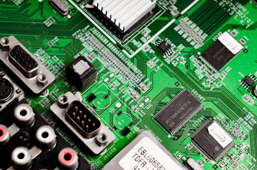
An arcade PCB (Printed Circuit Board) is the core component of any arcade machine, acting as its “brain” and “heart.” It contains all essential parts for game operation, including CPU, RAM, graphics and audio chips, ROM chips (for game software), voltage regulators, and connectors for controls, displays, and power.
Unlike standard PCBs, arcade PCBs are custom-made for specific games, with circuitry tailored to each game’s unique gameplay, graphics, and sound. Without a functional PCB, an arcade cabinet is non-operational, as all game logic, visuals, and audio depend on it.
Arcade PCBs come in different form factors, single-board (classic games) and multi-board (complex modern arcades), and vary by era, with older 8-bit/16-bit models having simpler components than modern ones with multi-core processors. Regardless of type, their core purpose is to turn electronic signals into an interactive arcade gaming experience.
How to Identify Arcade PCB?
Identifying an arcade PCB is straightforward once you know what to look for start with the most visible features, then move to component details. The first step is to check for labels or silk-screened text on the board itself; most manufacturers print the game title, model number, or manufacturer name directly on the PCB (usually near the edge or center). If no label exists, focus on the components and form factor.
Use this table to compare key identifying features of common arcade PCB types, making it easy to distinguish between models:
| PCB Type | Key Identifying Features | Common Examples |
| Single-Board Classic | Small to medium size (6-12 inches), 8-16 ROM chips, silk-screened game title, edge connector for power/controls | Pac-Man, Space Invaders, Donkey Kong |
| Multi-Board System | Multiple connected PCBs (CPU, graphics, sound), larger size, more components, separate power connectors for each board | Street Fighter II, Mortal Kombat, Tekken |
| Modern Arcade PCB | Slim design, fewer physical components (integrated chips), USB or HDMI connectors, compatibility with modern displays | Newer fighting games, racing arcades, retro console ports |
| Bootleg PCB | No brand labeling, mismatched components, poor soldering, generic silk-screen text | Unlicensed copies of classic games |
Additional tips: Count the IC chips (integrated circuits) with 8 or more pins this can help narrow down the game type. Check for a notch or arrow on the PCB, which indicates the orientation of components like ROM chips. If you’re still unsure, take clear photos of the board (both sides) and compare the component layout to known arcade PCB databases or repair guides.
How Much Voltage Does Arcade PCB Need?
Most arcade PCBs require three primary DC voltages to operate, with +5V being the most critical. The exact voltage requirements vary slightly by PCB model, but the standard ranges are consistent across most arcade machines. You must match the voltage supply to the PCB’s specifications too much voltage will fry components, while too little will cause the game to malfunction or not start at all.
Here’s the breakdown of standard arcade PCB voltage requirements, organized by importance:
- +5V DC: This is the primary voltage for the PCB’s core components (CPU, RAM, ROM chips, logic circuits). 90% of arcade PCBs use +5V as their main power source, with a tolerance of ±0.2V (so 4.8V to 5.2V is acceptable). A stable +5V supply is non-negotiable fluctuations will cause game crashes, glitches, or permanent component damage.
- +12V DC: Used for audio amplifiers, coin door lights, LED strips, and some auxiliary components. Most PCBs draw minimal current from +12V, but it’s still required for full functionality (especially sound). The tolerance here is ±0.5V (11.5V to 12.5V).
- -5V DC: Less common in modern arcade PCBs, but essential for sound circuits in older games (1980s and early 1990s). If your PCB has a dedicated sound chip (e.g., YM2612), it may require -5V with a tolerance of ±0.2V (-5.2V to -4.8V). Newer PCBs often omit -5V, as their sound circuits are powered by +5V or +12V.
Amperage is just as important as voltage. Most arcade PCBs require a power supply that can deliver 2-5 amps (A) at +5V, 1-2A at +12V, and 0.5A or less at -5V (if needed). Always check the PCB’s silk-screen or the game manual for exact amperage requirements using a power supply with insufficient amperage will cause voltage drops and system failures.
How to Check Arcade PCB Voltage?
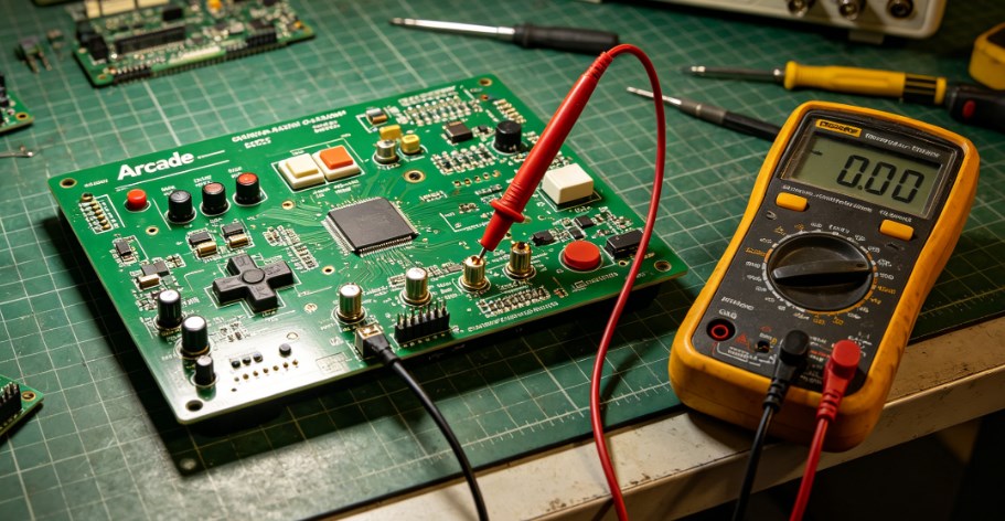
Checking arcade PCB voltage is a simple process that requires a digital multimeter no advanced tools needed. The goal is to verify that the PCB is receiving stable, correct voltage from the power supply, which helps diagnose issues like game crashes, no power, or glitches. Follow these steps exactly to avoid damaging the PCB or multimeter:
1. Prepare the tools: Get a digital multimeter, and set it to DC voltage mode (look for the “V⎓” symbol). Set the range to 20V (this covers all standard arcade voltages, so you won’t need to adjust it). Ensure the multimeter’s batteries are working test it by touching the two probes together; it should read 0V.
2. Power off the arcade machine: Unplug the power cord from the wall outlet to avoid electric shock. Wait 30 seconds to allow capacitors to discharge this prevents residual voltage from interfering with the test.
3. Locate the power connector on the PCB: The power connector is usually a small plastic block with pins labeled “+5V,” “+12V,” “-5V,” and “GND” (ground). If the labels are missing, refer to the PCB’s silk-screen or game manual to identify the pins.
4. Power on the machine: Plug the power cord back in and turn on the arcade machine. Do not touch any components on the PCB while it’s powered on static electricity or accidental contact can damage sensitive chips.
5. Test the voltage: Hold the multimeter’s black probe (negative) firmly against the GND pin. Use the red probe (positive) to touch the +5V pin first. The multimeter should read between 4.8V and 5.2V. Repeat for the +12V pin (11.5V to 12.5V) and -5V pin (-4.8V to -5.2V, if present).
6. Interpret the results: If the voltage is within the acceptable range, the power supply is working correctly. If it’s too high or too low, the power supply is faulty and needs to be replaced. If the voltage fluctuates (e.g., jumps from 4.5V to 5.5V), the power supply is unstable and should be replaced immediately to prevent PCB damage.
Pro tip: Test the voltage at both the power supply connector and the PCB’s power pins. If the voltage is correct at the power supply but incorrect at the PCB, there’s a loose wire or damaged connector that needs to be fixed.
How to Hook Up Arcade PCB?
Hooking up an arcade PCB is a step-by-step process that requires connecting power, controls (joysticks, buttons), display, and sound. The key is to match the PCB’s connectors to the corresponding components in the arcade cabinet misconnections will cause malfunctions or damage. Follow these steps for a safe, successful setup:
1. Prepare the cabinet: Ensure the arcade cabinet is powered off and unplugged. Remove the back panel to access the interior. Clear any dust or debris from the cabinet to avoid short circuits.
2. Mount the PCB: Use screws to secure the PCB to the cabinet’s mounting bracket. Ensure the PCB is level and not touching any metal components (this prevents short circuits). Use standoffs if needed to elevate the PCB slightly.
3. Connect the power supply: Plug the power supply’s connector into the PCB’s power port. Match the pins carefully most power connectors are keyed (have a notch) to prevent reverse insertion, but double-check the labels (+5V, +12V, -5V, GND) to be sure. Do not force the connector if it doesn’t fit, it’s oriented incorrectly.
4. Connect controls: The PCB has a dedicated connector for joysticks and buttons (often called a “control harness”). Plug the control harness into the PCB’s control port. Each button and joystick direction is wired to a specific pin refer to the PCB’s manual to ensure the harness is connected correctly. Test the controls by pressing buttons and moving the joystick; if they don’t respond, check the wiring.
5. Connect the display: Most arcade PCBs use a VGA, HDMI, or RGB connector for the display. Plug the display cable into the PCB’s display port and the other end into the arcade’s monitor. Ensure the display is set to the correct resolution (most classic PCBs use 4:3 aspect ratio).
6. Connect sound: Plug the speaker wires into the PCB’s audio port (labeled “AUDIO OUT” or “SPEAKER”). If the PCB has separate left and right audio channels, connect each wire to the corresponding speaker.
7. Test the setup: Plug in the power cord and turn on the arcade machine. The game should boot up, and all controls, display, and sound should work. If there’s no power, check the power supply and connections. If the game boots but controls don’t work, recheck the control harness.
Pro tip: Take photos of the original PCB’s connections before removing it (if replacing an old PCB). This makes it easy to match the wiring to the new PCB.
How to Connect Speakers to Arcade PCB?
Connecting speakers to an arcade PCB is simple, but you must match the speaker’s impedance (ohms) to the PCB’s audio output to avoid damaging the sound chip. Most arcade PCBs work with 8-ohm or 4-ohm speakers check the PCB’s silk-screen or manual for the exact impedance requirement. Follow these steps to connect speakers correctly:
1. Gather the tools: You’ll need speakers (matching the PCB’s impedance), speaker wire (18-22 gauge), wire strippers, and electrical tape (or heat shrink tubing).
2. Prepare the speaker wire: Cut two lengths of speaker wire (long enough to reach from the PCB to the speakers). Strip 1/4 inch of insulation from each end of the wire to expose the copper strands. Twist the strands together to prevent fraying.
3. Locate the PCB’s audio port: The audio port is usually labeled “AUDIO OUT,” “SPEAKER,” “LEFT,” or “RIGHT.” Most PCBs have two terminals (positive and negative) for each speaker look for “+” and “-” labels.
4. Connect the wire to the PCB: Attach one end of the speaker wire to the PCB’s positive terminal (+) and the other end to the negative terminal (-). Use electrical tape to secure the wires to the terminals this prevents them from coming loose.
5. Connect the wire to the speaker: Attach the other end of the wire to the speaker’s positive and negative terminals (match “+” to “+” and “-” to “-”). Again, secure the wires with electrical tape or heat shrink tubing.
6. Test the sound: Turn on the arcade machine and play a game. The sound should be clear and free of distortion. If there’s no sound, check the wire connections (ensure they’re secure and matched correctly) or test the speakers with another device to confirm they’re working.
Note: If the PCB has a built-in audio amplifier, you can connect speakers directly. If not, you’ll need an external amplifier between the PCB and speakers connect the PCB’s audio output to the amplifier, then the amplifier to the speakers.
How to Test Arcade PCB?
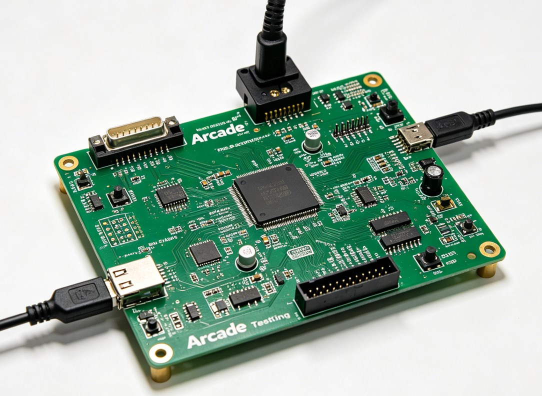
Testing an arcade PCB ensures it’s functional before installing it in a cabinet, saving you time and frustration. The test covers power, graphics, sound, and controls, and requires a few basic tools: a power supply (matching the PCB’s voltage), a display (monitor or TV), speakers, and a control harness (joystick and buttons). Follow these steps to test the PCB thoroughly:
1. Set up the test bench: Place the PCB on a non-conductive surface (e.g., a wooden table) to prevent short circuits. Connect the power supply to the PCB’s power port ensure the voltage and amperage match the PCB’s requirements.
2. Connect the display: Plug the display cable into the PCB’s display port and turn on the display. Set the display to the correct input (e.g., VGA, HDMI).
3. Connect speakers: Attach speakers to the PCB’s audio port (as outlined in the previous section).
4. Connect controls: Plug the control harness (joystick and buttons) into the PCB’s control port.
5. Power on the PCB: Turn on the power supply. The PCB should power up within 2-3 seconds, and the display should show the game’s title screen or boot sequence.
6. Test graphics: Check for clear, distortion-free visuals. Look for glitches, missing sprites, or color issues these indicate a faulty graphics chip or ROM.
7. Test sound: Play the game and listen for clear audio. Check for static, distortion, or missing sound effects this could mean a faulty sound chip or speaker connection.
8. Test controls: Press all buttons and move the joystick in all directions. Ensure each input is registered in the game (e.g., the character moves when the joystick is pushed, buttons trigger actions).
9. Test stability: Let the game run for 10-15 minutes. If it crashes, freezes, or resets, there’s a problem with the power supply, overheating, or a faulty component (e.g., a bad ROM chip).
If the PCB fails any test: Check the power supply voltage (as outlined earlier), inspect for loose components or damaged traces, and test the ROM chips (see the next section). For more complex issues, use a multimeter to check for continuity in the PCB’s traces.
How to Use an Arcade PCB?
Using an arcade PCB is simple once it’s properly hooked up, but there are a few key steps to ensure optimal performance and longevity. Whether you’re using a classic or modern PCB, follow these guidelines to get the most out of your arcade machine:
1. Power on correctly: Always turn on the arcade machine’s power supply first, then the display. This prevents voltage spikes from damaging the PCB’s components. When turning off, reverse the order: turn off the display first, then the power supply.
2. Monitor temperature: Arcade PCBs generate heat during operation, especially older models. Ensure the cabinet has proper ventilation (e.g., fans, vents) to prevent overheating. Avoid placing the cabinet in direct sunlight or near heat sources (e.g., radiators).
3. Handle with care: Never touch the PCB’s components while it’s powered on. If you need to adjust connections or inspect the board, turn off the power and unplug the machine first. Use an anti-static wristband to prevent static discharge, which can destroy sensitive chips.
4. Load games correctly: For PCBs with removable ROM chips, ensure the chips are seated properly (see the next section) before powering on. If the game doesn’t load, check the ROM chips for damage or misalignment.
5. Perform regular checks: Every 1-2 months, power off the machine, unplug it, and inspect the PCB for dust, loose components, or corrosion. Clean the PCB (as outlined below) to prevent dust buildup, which can cause short circuits.
6. Troubleshoot minor issues: If the game glitches or freezes, power off the machine, wait 30 seconds, then power it back on. This often resolves temporary issues caused by voltage fluctuations or overheating. If the problem persists, check the power supply and connections.
Pro tip: For vintage PCBs, avoid leaving the machine on for extended periods (e.g., 8+ hours) to reduce wear on components. Modern PCBs are more durable but still benefit from occasional breaks to prevent overheating.
How to Clean Arcade PCB?
Cleaning an arcade PCB is critical for preventing malfunctions dust, dirt, and corrosion can cause short circuits, poor connections, and component failure. The process is simple but requires care to avoid damaging sensitive components. Use only the right tools and cleaning solutions to ensure safety and effectiveness:
1. Prepare the tools: You’ll need high-purity isopropyl alcohol (IPA, 90% or higher) or anhydrous ethanol (99% or higher), anti-static wristband, soft-bristled brush (e.g., an old toothbrush), lint-free cloths (or coffee filters), and a small container for the cleaning solution. Avoid low-purity alcohol as it contains too much water and can cause corrosion.
2. Power off and disconnect: Unplug the arcade machine and remove the PCB from the cabinet. Put on the anti-static wristband to prevent static discharge. Place the PCB on a non-conductive surface.
3. Remove loose dust: Use the soft-bristled brush to gently sweep away loose dust and debris from the PCB’s surface and components. Be careful not to bend any pins or damage small components (e.g., capacitors).
4. Clean with alcohol: Pour a small amount of IPA or ethanol into the container. Dip the lint-free cloth or a cotton swab into the solution (don’t soak it just dampen it). Gently wipe the PCB’s surface, focusing on areas with visible dirt, grease, or corrosion. For hard-to-reach areas (e.g., between components), use a cotton swab.
5. Clean connectors and pins: Use a cotton swab dampened with alcohol to clean the PCB’s edge connector and component pins. This removes oxidation and dirt that can cause poor connections.
6. Dry the PCB: Allow the PCB to air dry in a well-ventilated area for at least 30 minutes (or overnight for best results). Do not use a hair dryer or heat source this can damage components. Ensure the PCB is completely dry before reconnecting it to the power supply.
7. Reassemble: Once dry, reattach the PCB to the cabinet and reconnect all cables. Power on the machine to confirm it’s working correctly.
Note: Avoid using water, harsh chemicals, or abrasive materials (e.g., paper towels) as these can damage the PCB’s solder mask and components. For heavy corrosion, use a specialized electronic cleaner (ensure it’s compatible with PCBs) and a small brush to gently remove the corrosion.
How to Remove ROM Chips from Arcade PCB?
ROM chips (Read-Only Memory) store the game’s software, and removing them may be necessary for repairs, upgrades, or replacement. The process requires care to avoid damaging the ROM chip or the PCB’s socket. Follow these steps to safely remove ROM chips:
1. Prepare the tools: You’ll need an EPROM puller (preferred) or a small flathead screwdriver, anti-static wristband, and a clean, dry surface to place the ROM chips.
2. Power off and disconnect: Unplug the arcade machine and remove the PCB from the cabinet. Put on the anti-static wristband to prevent static discharge.
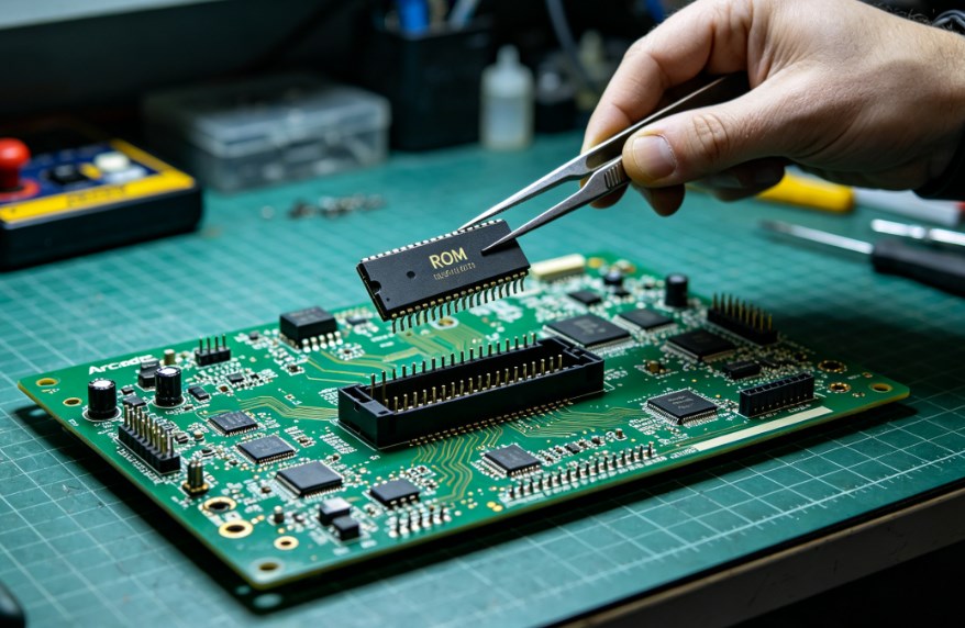
3. Locate the ROM chips: ROM chips are rectangular integrated circuits (ICs) with 16-40 pins, usually seated in a socket on the PCB. They are often labeled with the game’s title or a part number.
4. Identify the notch: Each ROM chip has a small notch on one end, which indicates pin 1. The PCB’s socket will also have a notch or arrow to match the chip’s orientation note this before removing the chip to ensure correct reinstallation.
5. Remove the chip: If using an EPROM puller, clamp the puller around the edges of the ROM chip (avoid touching the pins) and gently pull straight up. If using a screwdriver, insert the flathead between the chip and the socket (on one side) and gently twist to lift the chip slightly. Move the screwdriver to the other side and repeat until the chip is loose, then pull it straight up. Do not pry too hard this can damage the socket or the chip’s pins.
6. Store the chip: Place the removed ROM chip on an anti-static mat or in an anti-static bag. Label the chip with the game title and its position on the PCB (e.g., “ROM 1”) to avoid confusion if you’re reinstalling it later.
Pro tips: Remove one ROM chip at a time to avoid mixing them up. If the chip is stuck, gently rock it back and forth (without bending the pins) to loosen it. Never remove or insert ROM chips while the PCB is powered on this will fry the chip and possibly the PCB.
FAQs About Arcade PCB Board
Q1: Why won’t my arcade PCB power on even with the correct voltage?
A1: Common issues: loose power connections, faulty power supply, damaged power connector. Check connections, test power supply with a multimeter, clean or replace damaged connector; replace faulty voltage regulator if needed.
Q2: How do I know if my arcade PCB’s ROM chips are bad?
A2: Signs: game crashes, missing graphics, distorted sound, blank screen. Check ROM seating first; test with an EPROM programmer if issues persist. Replace bad ROM chips matching the game’s model and part number.
Q3: Can I use a different power supply for my arcade PCB?
A3: Only if it matches voltage (±tolerance), amperage (≥ requirement) and polarity. Reverse polarity will damage components; check power supply specs first.
Q4: How often should I clean my arcade PCB?
A4: Every 3-6 months (2-3 months in dusty areas). Clean immediately if corrosion, grease or dirt is present; power off and unplug before cleaning.
Q5: Can I repair a broken trace on my arcade PCB?
A5: Yes. Locate the break with a multimeter (continuity mode), clean the area, solder a 22-24 gauge copper wire across the break, and test after cooling.
Q6: What’s the difference between a bootleg arcade PCB and an original one?
A6: Original: official manufacture, high-quality components, clear labeling, proper soldering, reliable. Bootleg: unlicensed, cheap components, poor soldering, no branding, prone to glitches and failure.
Q7: How do I prevent static damage to my arcade PCB?
A7: Wear an anti-static wristband, hold PCB by edges, store in anti-static bag, work on non-conductive surfaces, avoid static-generating materials and clothing.