The symbol of light emitting diode is one of the first schematic symbols engineers, buyers, and technicians need to understand when reading a circuit diagram. It looks similar to a standard diode symbol, but it includes two small arrows pointing outward to show light emission. This small difference matters because an LED is not only a one-way current device; it is also an optical component with color, brightness, wavelength, viewing angle, current rating, and heat limits.
For PCB and PCBA projects, LED selection is rarely about choosing “a small light.” The LED must match the circuit voltage, current, polarity marking, soldering process, enclosure design, and visual requirement. A wrong LED footprint, reversed polarity, excessive current, or poor heat path can cause dim light, early failure, color mismatch, or PCB assembly rework.
What Is the Symbol for LED?
The LED symbol is a diode symbol with two arrows pointing away from it. The diode part shows that current flows in one direction. The outward arrows show that the device emits light when forward biased.
In most circuit diagrams, the LED has two terminals:
| LED Terminal | Meaning | Polarity |
|---|---|---|
| Anode | Positive side | Connects to positive voltage through a current-limiting path |
| Cathode | Negative side | Usually connects toward ground or the lower voltage side |
The cathode side is often shown with a vertical line in the symbol. The anode is the opposite side. Conventional current flows from anode to cathode when the LED is forward biased.
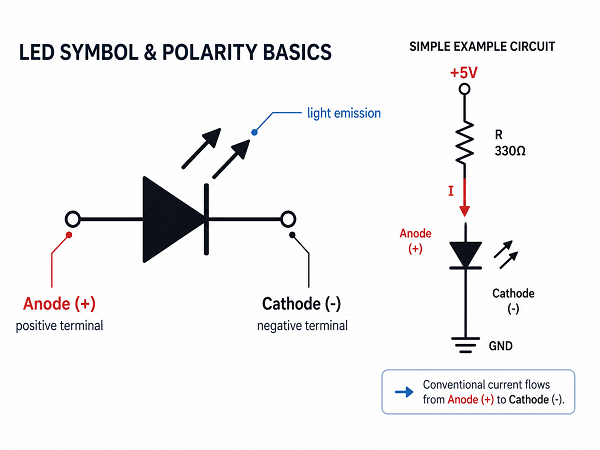
A simple LED circuit usually includes a resistor in series with the LED. The resistor limits current and protects the LED. Without current control, even a small LED can be damaged by excessive current.
For example, if a red LED has a forward voltage of about 2.0V and runs at 10mA from a 5V supply, the resistor value is approximately:
R = (5V − 2V) / 0.01A = 300Ω
A nearby standard value such as 330Ω is commonly used. For production designs, always check the LED datasheet because forward voltage and luminous intensity vary by part number, color, bin, and operating current.
What Is the Difference Between LED Symbol and Diode Symbol?
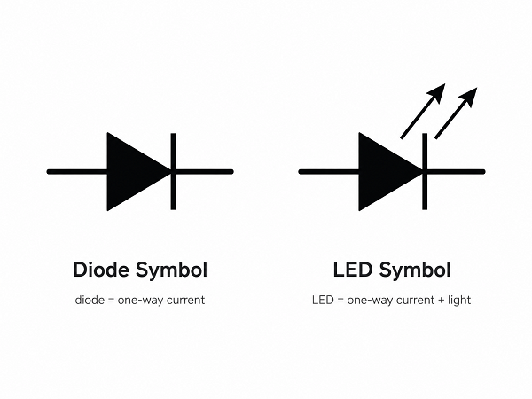
The LED symbol is based on the normal diode symbol. The key difference is the two arrows pointing outward.
| Item | Diode Symbol | LED Symbol |
|---|---|---|
| Main function | Allows current in one direction | Allows current in one direction and emits light |
| Symbol feature | Diode symbol only | Diode symbol plus outward arrows |
| Circuit concern | Rectification, protection, switching | Polarity, current, brightness, color, heat, optical position |
| Typical PCB issue | Wrong diode orientation or rating | Wrong polarity, wrong color, wrong footprint, poor light alignment |
A standard diode may be selected mainly for voltage, current, switching speed, and package. An LED also needs optical and mechanical review. In a PCB project, the LED position must align with the enclosure window, light pipe, lens, button area, or display panel. A correct schematic symbol does not guarantee a correct mechanical result.
What Does a Light-Emitting Diode Look Like?
A light-emitting diode can look very different depending on package type and application.
| LED Type | What It Looks Like | Common PCB Use |
|---|---|---|
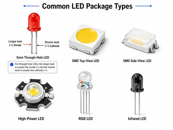
| 3mm / 5mm through-hole LED | Round epoxy lens with two leads | Panels, prototypes, equipment indicators |
| SMD top-view LED | Small rectangular package emitting upward | Consumer electronics, control boards |
| SMD side-view LED | Thin package emitting from the side | Edge lighting, buttons, display panels |
| High-power LED | Larger package, often with thermal pad | Lighting, automotive, industrial illumination |
| RGB LED | Multi-chip LED in one package | Color indicators, displays, decorative lighting |
| Infrared LED | Often clear or dark lens | Sensors, remote control, optical communication |
| UV LED | Specialty package, often with thermal concerns | Curing, inspection, sterilization-related equipment |
For through-hole LEDs, the longer lead is usually the anode, and the shorter lead is usually the cathode. The flat side of the epoxy body often marks the cathode. For SMD LEDs, do not rely on appearance alone. The polarity mark must be checked against the datasheet and PCB footprint.
In assembled products, the LED may not be visible as a bare component. It may sit under a plastic lens, silicone light guide, membrane overlay, or enclosure window. That means PCB placement tolerance, LED height, viewing angle, and light leakage control can become part of the engineering review.
How to Identify Anode and Cathode in the LED Symbol?
In the LED symbol, the anode is the positive side, and the cathode is the negative side. The cathode is usually the side with the vertical bar. The anode is on the opposite side.
A practical way to remember it:
| Identification Method | Anode | Cathode |
|---|---|---|
| Schematic symbol | Side without vertical bar | Side with vertical bar |
| Through-hole LED lead | Usually longer lead | Usually shorter lead |
| Through-hole LED body | Round side | Flat edge often marks cathode |
| PCB silkscreen | May be marked “A” or “+” | May be marked “K,” “C,” line, or bar |
| Datasheet | Pin named A | Pin named K or C |
For PCB manufacturing and assembly, polarity must be controlled in three places: schematic, footprint, and assembly drawing. If these three documents disagree, the assembler may mount the LED incorrectly even if the BOM is correct.
For SMD LEDs, never assume that the package marking follows one universal rule. Some LED manufacturers mark the cathode, while others mark the anode. Before production, compare the datasheet polarity diagram with the PCB silkscreen and pick-and-place file.
What Is the Function of the Light-Emitting Diode?
The light-emitting diode function is to convert electrical energy into light when current flows through it in the forward direction. In real products, LEDs serve several functions:
- Power-on indication
- Charging or battery status display
- Fault warning
- Signal transmission
- Backlighting
- Machine vision illumination
- Optical sensing
- Automotive lighting
- Medical and industrial equipment indication
- UV curing or inspection
The electrical function and visual function should be considered together. A small status LED on a control board may only need 2–10mA. A high-power lighting LED may need constant-current driving, metal-core PCB, ceramic substrate, heat sink, thermal interface material, and optical lens design.
How Does a Light Emitting Diode Work?
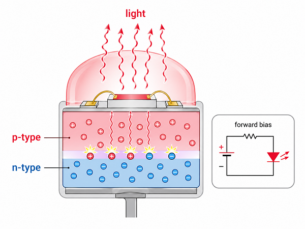
A light emitting diode works through electron-hole recombination inside a semiconductor junction. When the LED is forward biased, electrons and holes recombine and release energy as photons. The semiconductor material determines the emitted wavelength, which is why different LED materials produce different colors.
The LED does not behave like a resistor. Once the forward voltage is reached, current can rise quickly. That is why LEDs normally need one of the following current control methods:
| Current Control Method | Best For | Notes |
|---|---|---|
| Series resistor | Simple indicators, low-cost circuits | Easy, but current changes with supply voltage |
| Constant-current driver | Lighting, stable brightness | Better control, higher cost |
| PWM dimming | Brightness control | Common in displays and backlighting |
| Linear LED driver | Low-noise applications | Generates heat in the driver |
| Switching LED driver | High-efficiency lighting | Requires careful layout and EMI control |
Forward voltage varies by LED color and current. Typical values are:
| LED Color | Typical Forward Voltage |
|---|---|
| Red | 1.8–2.2V |
| Yellow / Amber | 1.9–2.2V |
| Green | 2.0–3.2V |
| Blue | 2.8–3.4V |
| White | 2.8–3.5V |
| UV | 3.0–4.0V, depending on type |
These are reference ranges, not substitute values for a datasheet. For PCB layout, the designer also needs the LED current, power dissipation, solder pad size, thermal pad design, and spacing from heat-sensitive parts.
LED Light Wavelength Chart
LED color is strongly related to wavelength. Visible LEDs usually emit light within a specific wavelength range, while white LEDs are commonly made by using a blue LED chip with phosphor conversion.
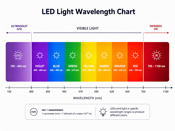
The following chart gives practical reference ranges:
| LED Color | Typical Wavelength Range | Common Use |
|---|---|---|
| Ultraviolet LED | Below 400 nm | Curing, inspection, sensing |
| Violet | 380–450 nm | Specialty lighting, optical devices |
| Blue | 450–495 nm | Indicators, displays, white LED base chips |
| Green | 495–570 nm | Status indicators, panels, traffic signals |
| Yellow | 570–590 nm | Warning lights, equipment panels |
| Orange / Amber | 590–620 nm | Automotive indicators, industrial alarms |
| Red | 620–750 nm | Power indicators, alarms, optical signals |
| Infrared LED | Above 700 nm | Remote control, sensors, night vision |
Wavelength is not the same as color name. Two green LEDs from different suppliers may look different if their dominant wavelength and brightness bins are not controlled. This matters in products with multiple indicators, front panels, medical devices, consumer electronics, and automotive lighting.
Main Types of LED Symbols and LED Connections
LED symbols can appear in several forms depending on circuit function. The base symbol remains a diode with outward arrows, but the connection style changes.
| LED Connection Type | Symbol / Circuit Meaning | Design Note |
|---|---|---|
| Single LED | One LED used as an indicator | Needs current limiting |
| LED with resistor | LED and resistor in series | Common for low-current indicators |
| LED array | Multiple LEDs connected in series, parallel, or matrix | Current balance must be reviewed |
| RGB LED | Red, green, and blue LED chips in one package | Can be common anode or common cathode |
| Bi-color LED | Two LED chips in one package | Polarity may control color |
| Optocoupler LED | LED inside an optocoupler package | Used for signal isolation |
| Photointerrupter LED | LED paired with optical sensor | Alignment matters |
| LED matrix | Rows and columns of LEDs | Requires scanning and driver control |
Series LED connections are common when using a higher supply voltage. Parallel LED connections are simple but can create uneven current sharing if each LED does not have its own resistor or current control path.
For RGB LEDs, the common pin must be confirmed. A common-anode RGB LED connects the shared pin to positive voltage. A common-cathode RGB LED connects the shared pin to ground. Using the wrong type can require circuit redesign.
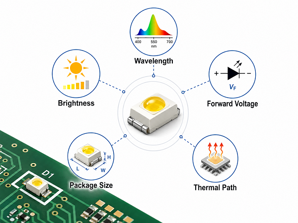
How to Choose the Right LED for a Circuit or PCB Project?
LED selection should begin with the product requirement, not only the LED package. The right part must fit the electrical design, optical target, mechanical structure, soldering process, and purchasing plan.
Use this checklist before confirming the BOM:
| Selection Factor | What to Confirm | Why It Matters |
|---|---|---|
| Color / wavelength | Color name, dominant wavelength, bin | Prevents visible color mismatch |
| Brightness | Luminous intensity or luminous flux | Controls visibility and power use |
| Forward current | Rated current and test current | Affects resistor, driver, and heat |
| Forward voltage | Typical and maximum values | Needed for circuit calculation |
| Package size | 0603, 0805, 1206, PLCC, high-power, etc. | Must match footprint and assembly capability |
| Viewing angle | Narrow, medium, wide | Affects panel visibility |
| Polarity marking | Datasheet pin map and package mark | Prevents reversed assembly |
| Thermal path | Copper area, thermal pad, MCPCB, ceramic PCB if needed | Important for high-power LEDs |
| Soldering profile | Reflow, wave soldering, hand soldering limits | Prevents heat damage |
| Availability | Brand, alternative part, lifecycle | Reduces supply risk |
For simple indicator LEDs, FR4 PCB is usually enough. For high-brightness LED modules, automotive lighting, UV LEDs, or compact high-power designs, thermal design becomes a purchasing factor. Aluminum PCB, copper-base PCB, or ceramic PCB may be considered when heat density exceeds what standard FR4 can handle.
How to Test LED Polarity?
LED polarity can be tested before assembly, during inspection, or after PCBA production. The method depends on component type and access to the terminals.
| Test Method | How It Works | Suitable For |
|---|---|---|
| Multimeter diode mode | The LED may glow slightly when forward biased | Loose LEDs, simple checks |
| Low-voltage supply with resistor | Apply safe current through a resistor | Through-hole and SMD LEDs |
| Datasheet verification | Compare package mark and pin map | SMD LEDs and production BOM review |
| PCB continuity and polarity check | Confirm anode and cathode pads from schematic | Pre-assembly inspection |
| Functional test | Power the board under controlled conditions | Finished PCBA |
When using a power supply, always include a current-limiting resistor or current limit setting. Do not connect an unknown LED directly across a battery or power supply. Some LEDs fail instantly under excessive current.
For production, polarity testing should not rely only on manual visual inspection. Pick-and-place orientation, first article inspection, AOI settings, and functional test points should match the LED polarity requirement. This is especially important for dense SMD boards, RGB LEDs, side-view LEDs, and assemblies using similar-looking components with different orientations.
What Common Failures Happen When LEDs Are Used Incorrectly?
Most LED failures come from wrong current, wrong polarity, poor thermal path, unsuitable soldering, or mismatched optical requirements.
| Failure Mode | Likely Cause | Practical Prevention |
|---|---|---|
| LED does not light | Reversed polarity, open circuit, wrong footprint | Check symbol, PCB pad, datasheet, and assembly orientation |
| LED burns out | No current limiting or excessive current | Use resistor or LED driver with current control |
| LED is too dim | Low current, wrong resistor, low-efficiency LED, wrong wavelength | Verify current, brightness bin, and optical target |
| Color looks wrong | Wrong wavelength bin or supplier change | Specify wavelength/bin requirement |
| Brightness varies between units | Loose binning or current tolerance | Use tighter LED bin and stable current control |
| Early lumen decay | Excess heat or overdrive current | Improve thermal path and reduce current stress |
| Solder joint damage | Incorrect reflow profile or weak pad design | Follow reflow limits and proper footprint design |
| Intermittent lighting | Cracked solder joint, vibration, weak pad | Review pad size, solder fillet, and mechanical support |
| ESD damage | Poor handling or no protection | Use ESD controls and protective circuit where needed |
| Light leakage | Poor LED position or enclosure gap | Align LED with lens, light pipe, or overlay |
A small indicator LED may look like a low-risk component, but it can still cause customer complaints if the color, brightness, or panel alignment is wrong. For high-power LEDs, electrical and thermal margins are more critical because excess junction temperature shortens service life.
FAQs
What is the meaning of light emitting diode?
A light emitting diode is a semiconductor device that emits light when current flows through it in the forward direction. It is directional, so anode and cathode orientation must be correct.
Which side of an LED is positive and negative?
The anode is positive, and the cathode is negative. In the schematic symbol, the cathode is usually the side with the vertical line. On a physical LED, polarity must be checked using the datasheet, package mark, or lead shape.
Does an LED need a resistor?
A basic LED indicator usually needs a series resistor to limit current. High-power or precision lighting designs often use a constant-current driver instead of only a resistor.
What happens if an LED is connected backward?
A normal LED will not light when reverse biased. If the reverse voltage is too high, the LED may be damaged. Some circuits include reverse protection for this reason.
Is LED color decided by voltage?
LED color is mainly decided by semiconductor material and wavelength, not simply by supply voltage. However, different LED colors usually have different forward voltage ranges.
Can I replace one LED with another LED of the same size?
Not always. The package may fit, but the forward voltage, current rating, brightness, wavelength, viewing angle, polarity mark, and thermal behavior may be different.
What information should I provide for an LED PCB or PCBA quotation?
Provide Gerber files, BOM, LED datasheet, assembly drawing, polarity notes, operating current, voltage input, product application, quantity, test requirements, and any brightness or color matching requirement.
Is FR4 PCB suitable for LED products?
FR4 is suitable for many low-power LED indicators and control boards. For high-power LED lighting, UV LED modules, compact thermal designs, or automotive lighting, aluminum PCB, copper-base PCB, or ceramic PCB may be more suitable.
Understanding the symbol of light emitting diode helps engineers and buyers read schematics, confirm LED polarity, prevent assembly mistakes, and choose suitable LEDs for real PCB or PCBA projects. The LED symbol tells only part of the story. A reliable design also needs the right wavelength, current control, package, footprint, thermal path, and inspection method. For LED PCB fabrication, prototype assembly, or production review, EBest Circuit (Best Technology) can help check manufacturability, polarity marking, substrate selection, and quotation details. For project support, contact sales@bestpcbs.com.