PCB manufacturing PCB manufacturing
Home > Blog

circuit card assembly

Which Circuit Card Assembly Testing Methods Fit Your Manufacturing Needs?
Wednesday, May 6th, 2026

If your manufacturing line relies on consistent, reliable circuit card assemblies, how do you ensure each unit meets the standards your operations demand? How do you leverage circuit card assembly testing to choose the right approach and avoid costly rework, delays, and product failures?

Circuit card assembly testing is essential for consistent production, and navigating its many methods, equipment and requirements can be overwhelming. This guide helps you choose the right testing methods for your manufacturing needs, detect defects early, and maintain high-quality output.

Circuit Card Assembly Testing, https://www.bestpcbs.com/blog/2026/05/circuit-card-assembly-testing-2/

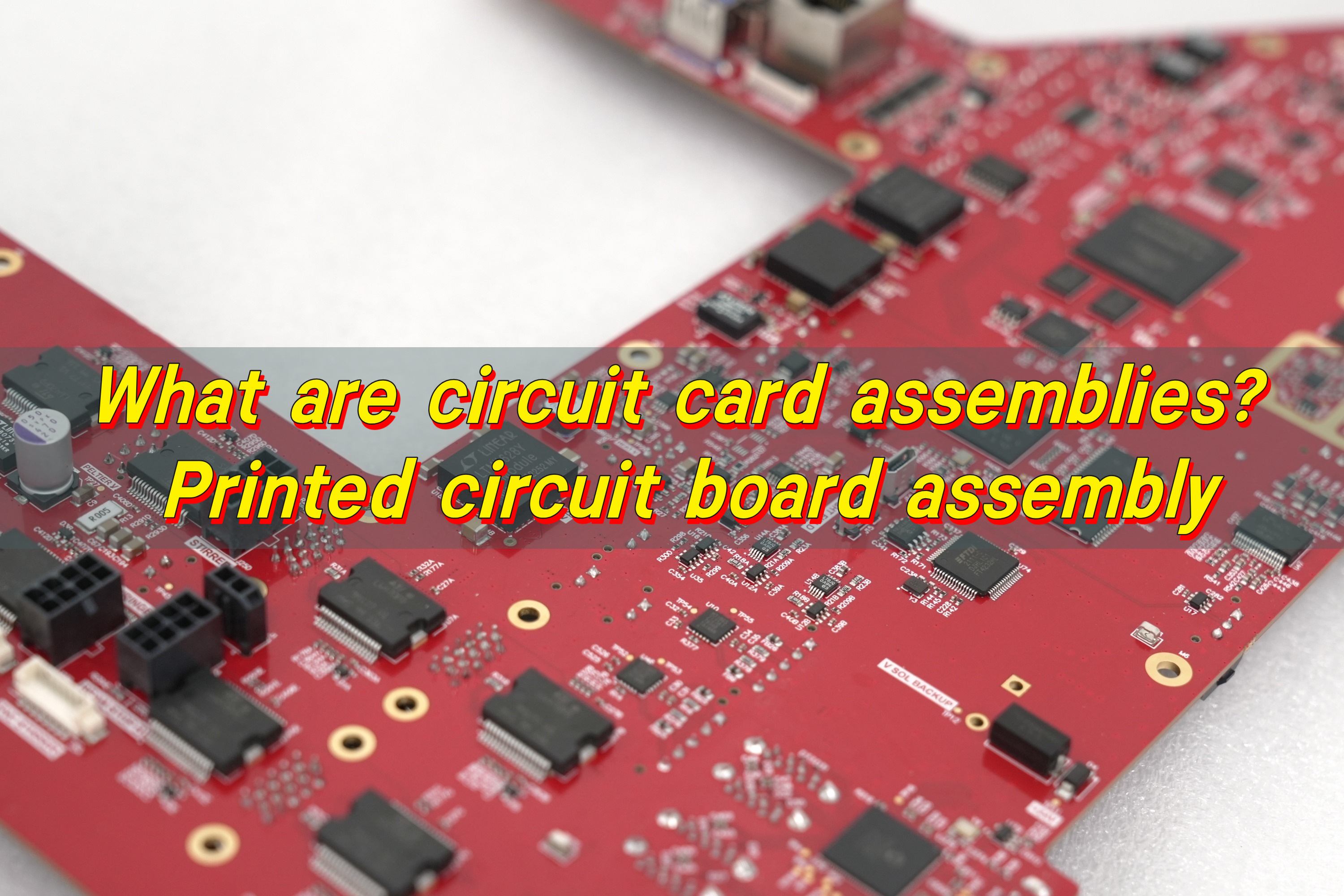
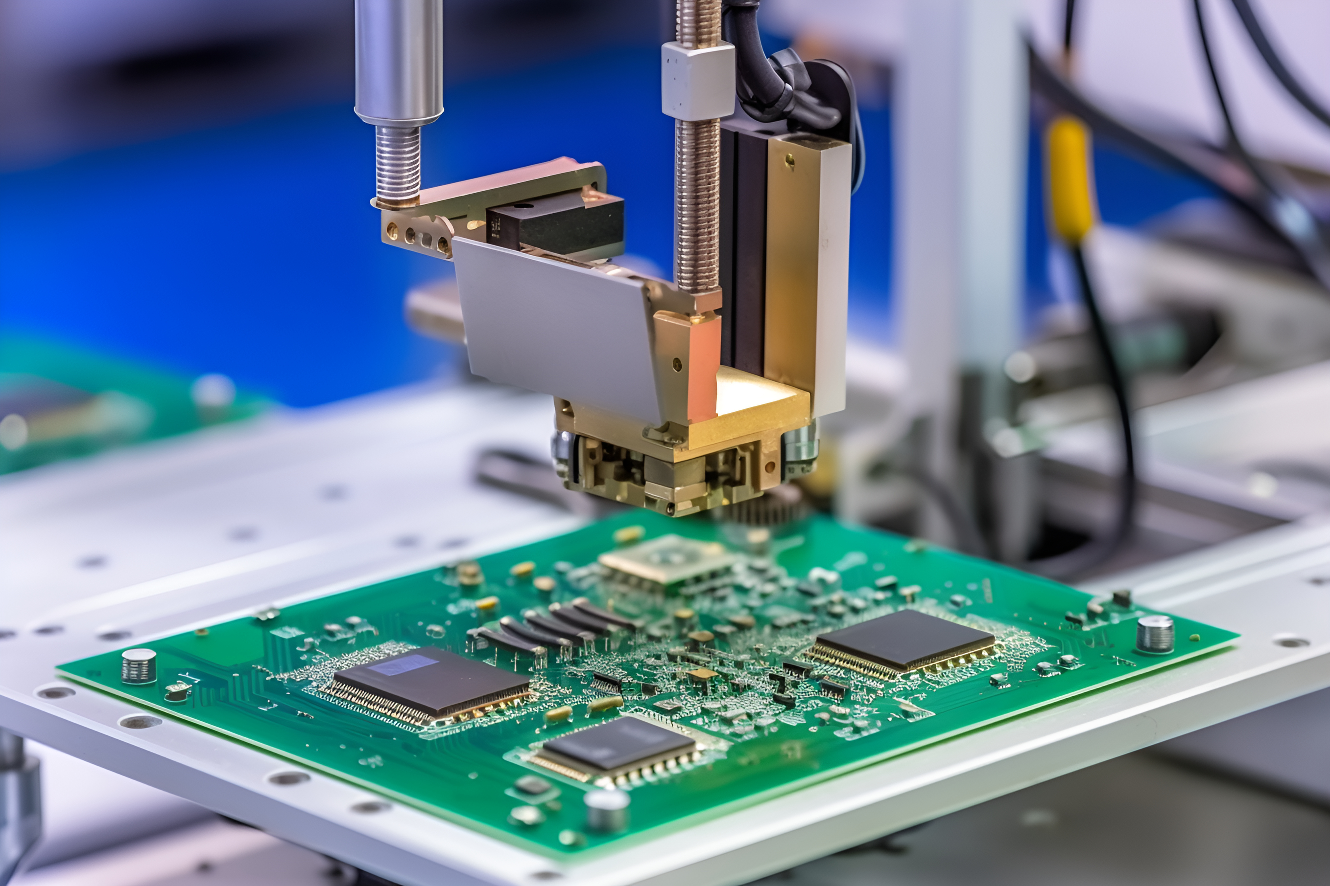
What Is Circuit Card Assembly Testing and How Does It Work?

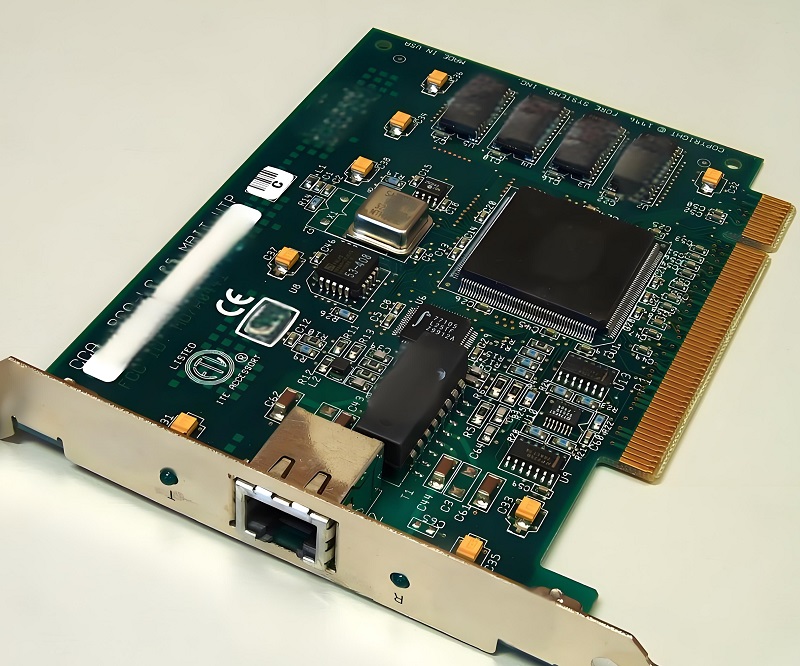
Circuit card assembly testing is a straightforward process designed to confirm that assembled circuit boards work as they should. It ensures each board meets the design requirements set for it and is free of any defects that could affect its performance or how long it lasts. Without this testing, even small issues can lead to bigger problems down the line, from product failures to wasted time and money.

At its core, this testing checks two key things: the physical condition of the assembly and its electrical functionality. It verifies that every component, from resistors and capacitors to solder joints and connections, is in the right place and working properly. This dual check helps catch both obvious surface issues and hidden problems that might not be visible to the naked eye.

The process itself is simple: controlled inputs are applied to the circuit card, and the outputs are measured and compared to predefined standards. Depending on the needs of the production run, testing methods can vary; some are automated for fast, high-volume testing, while others are more flexible for small batches or prototypes. The end goal is always the same: to catch issues early and ensure consistent, reliable quality.

Why Is Circuit Card Assembly Testing Critical for Product Quality and Reliability?

Circuit card assembly testing is critical for product quality and reliability. It safeguards electronic product performance and longevity, catches defects early to avoid faulty units, reduce rework costs and delays, ensures design compliance, and enhances long-term reliability while protecting brand trust.

  • Prevents Defective Products from Reaching Customers Unchecked defects in circuit card assemblies can lead to product failures, customer complaints, and reputational damage. Testing ensures only fully functional units leave the manufacturing line, protecting brand trust and reducing returns.
  • Reduces Rework and Production Costs Catching defects early in the manufacturing process is far less expensive than fixing them after assembly or after delivery. Testing eliminates the need for costly rework, scrap, and replacement parts, improving overall production efficiency.
  • Ensures Compliance with Design Specifications Circuit card assemblies must meet strict design requirements to work with other system components. Testing verifies that each assembly aligns with electrical, mechanical, and performance standards, preventing compatibility issues.
  • Enhances Long-Term Reliability Defects like poor solder joints or component misalignment may not cause immediate failure but can lead to premature breakdowns in the field. Testing identifies these hidden issues, ensuring assemblies perform consistently over their intended lifespan.
  • Minimizes Production Delays Unplanned rework or product recalls due to untested defects can halt production lines and delay deliveries. Consistent testing streamlines the manufacturing process, keeping operations on schedule and meeting customer deadlines.

What Are the Main Types of Circuit Card Assembly Testing Methods Available?

Choosing the right circuit card assembly testing method depends on factors like production volume, assembly complexity, and testing goals. Each method has unique strengths, designed to address specific testing needs from fast, automated checks for high-volume runs to flexible, fixtureless options for prototypes and complex assemblies. Below is a breakdown of the most common methods, their key features, and ideal use cases.

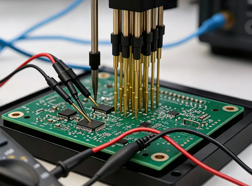
  • In-Circuit Testing (ICT) A popular method for high-volume production, ICT uses a bed-of-nails fixture to test individual components and connections on the circuit card assembly. It checks for component values, solder shorts, open circuits, and incorrect part placements. This method delivers fast, accurate results for mass-produced units.
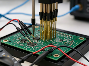
  • Flying Probe Testing A flexible, fixtureless method ideal for low-volume production, prototypes, or complex assemblies. Flying probe testers use movable probes to access test points, eliminating the need for custom fixtures. This approach works well for quick turnaround and design iterations.
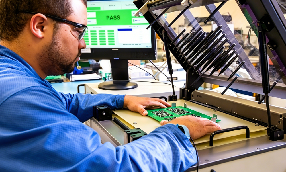
  • Functional Testing Verifies that the entire circuit card assembly operates as intended in real-world conditions. It applies inputs similar to those the assembly will encounter in use and measures outputs to ensure performance meets design standards. This type of testing is critical for validating end-to-end functionality.
  • Automated Optical Inspection (AOI) Uses high-resolution cameras and image analysis to check the physical appearance of the circuit card assembly. It detects surface defects like missing components, misaligned parts, solder bridging, and poor solder joints. AOI is often used as a first-pass test in production.
  • X-Ray Inspection Used for hidden defects that are invisible to the naked eye or AOI. Examples include internal solder joints in ball grid arrays (BGAs) or quad flat packages (QFPs). X-ray testing penetrates the assembly to check for voids, cold solder joints, and component misalignment.
Circuit Card Assembly Testing, https://www.bestpcbs.com/blog/2026/05/circuit-card-assembly-testing-2/

How Do Flying Probe Testing and In-Circuit Testing Differ in Circuit Card Assembly Testing?

FeatureFlying Probe TestingIn-Circuit Testing
Fixture RequirementNo custom fixture needed; uses movable probes to access test pointsRequires a custom bed-of-nails fixture tailored to the specific circuit card assembly
Production Volume SuitabilityIdeal for low-volume production, prototypes, and design iterationsOptimized for high-volume production, where fixture costs are offset by fast testing speeds
Testing SpeedSlower than ICT, as probes move to each test point individuallyFast, with simultaneous testing of multiple points via the bed-of-nails fixture
Complexity HandlingExcels with complex assemblies, fine-pitch components, and tight test point spacingMay struggle with very complex assemblies or limited test point access
CostLower upfront costs (no fixture), but higher per-unit testing costs for high volumesHigher upfront costs (fixture design and fabrication), but lower per-unit costs for high volumes
Turnaround TimeFast setup with no fixture, ideal for quick prototyping and small batchesLonger setup time due to fixture design and installation, better for consistent high-volume runs

What Common Defects Can Circuit Card Assembly Testing Detect?

Circuit card assembly testing plays a vital role in identifying a range of common defects that can arise during manufacturing, from visible surface issues to hidden flaws that may cause premature failure. These defects, which can stem from soldering mishaps, component placement errors, or material issues, can compromise the assembly’s functionality if left undetected. Below is a detailed breakdown of the most frequent defects and how testing methods uncover them.

  • Open Circuits: Breaks in the circuit path that prevent electrical current from flowing. These are often caused by poor solder joints, broken traces, or component lead issues. Continuity tests in ICT, flying probe testing, or functional testing can detect them.
  • Solder Shorts: Unintended electrical connections between two or more circuit points. These are typically caused by excess solder or solder bridging. AOI and X-ray testing are effective for identifying surface and hidden solder shorts.
  • Missing Components: Components that are not placed on the circuit card assembly during manufacturing. AOI and visual inspection (manual or automated) quickly detect missing resistors, capacitors, integrated circuits, and other parts.
  • Misplaced Components: Components placed in the wrong location or orientation, which can render the assembly nonfunctional. AOI and ICT verify component placement against design specifications.
  • Incorrect Component Values: Components with values that do not match the design. An example is a 1k resistor instead of a 10k resistor. ICT and functional testing measure component values to ensure accuracy.
  • Cold Solder Joints: Solder joints that do not form a proper bond with the component lead and circuit pad. These can lead to intermittent connections or complete failure. X-ray testing and functional testing can detect these hidden defects.
  • Component Damage: Physical damage to components such as cracked chips or bent leads. It also includes damage from electrostatic discharge (ESD) during manufacturing. AOI and visual inspection identify visible damage, while functional testing uncovers performance issues from hidden damage.

When Should You Perform Circuit Card Assembly Testing in the Manufacturing Process?

Circuit card assembly testing must be timed strategically throughout the manufacturing process to maximize effectiveness and minimize costs. The right testing timing ensures defects are caught early, rework is reduced, and final products meet quality standards. Below is a breakdown of key stages to perform testing, aligned with production workflows to keep operations efficient and reliable.

  • After Component Placement and Soldering: The first critical testing point is immediately after components are placed and soldered. This step catches surface-level defects like missing components, misplacement, and solder shorts early. It prevents additional assembly steps from increasing rework costs.
  • After Rework or Repair: Any time a circuit card assembly is reworked or repaired, testing is essential. It ensures the repair was successful and no new defects were introduced. This prevents faulty repaired units from moving forward in production.
  • Before Final Assembly: Testing before the circuit card assembly is integrated into the final product ensures it functions correctly with other system components. This step avoids costly disassembly if the assembly is defective.
  • Before Shipping: A final test before shipping confirms that the circuit card assembly meets all performance and quality standards. This is the last line of defense against defective products reaching customers.
  • During Prototype Development: Testing during prototype development helps validate the design. It identifies potential issues and allows for adjustments before mass production. This reduces the risk of costly design changes later in the process.

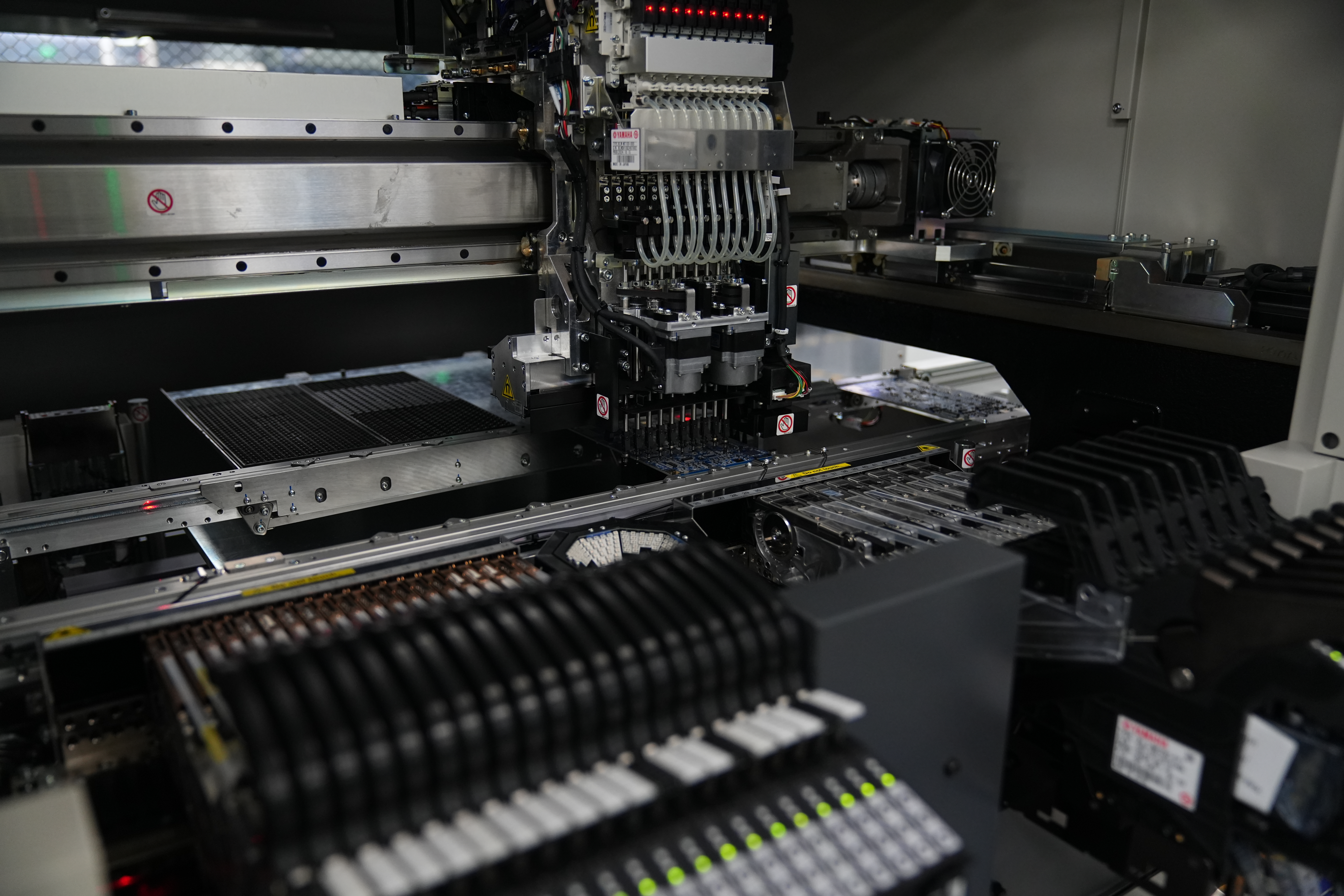
What Equipment Is Needed for Effective Circuit Card Assembly Testing?

Effective circuit card assembly testing relies on the right tools and equipment, tailored to your testing methods and production needs. The right equipment ensures accurate, efficient defect detection, whether for high-volume automated testing or flexible low-volume checks. Below is a breakdown of essential equipment and its role in reliable testing processes.

  • In-Circuit Test Fixtures: Custom bed-of-nails fixtures designed to match the test points of the specific circuit card assembly. These fixtures connect the assembly to the ICT machine for fast, automated testing.
  • Flying Probe Testers: Automated machines with movable probes that access test points without a custom fixture. They include high-precision motors and sensors to ensure accurate probe placement.
  • AOI Machines: High-resolution cameras, lighting systems, and image analysis software to detect physical defects. Advanced models include 3D capabilities for better detection of solder joint issues.
  • X-Ray Inspection Systems: X-ray sources and detectors to visualize internal components and solder joints. These systems are essential for testing BGAs, QFPs, and other components with hidden connections.
  • Functional Test Benches: Custom setups that simulate real-world operating conditions for the circuit card assembly. They include signal generators, power supplies, and measurement tools to verify performance.
  • Continuity Testers: Handheld or automated tools to check for open circuits and short circuits. These are useful for quick spot checks and manual testing of small batches.

How to Choose the Right Circuit Card Assembly Testing Service for Your Project?

Selecting the right service for circuit card assembly testing is key to ensuring accurate results, timely turnaround, and alignment with your project goals. With varying service capabilities and expertise, it’s critical to focus on factors that match your assembly type and production needs. Below are key considerations to guide your service selection process.

  • Verify Experience with Your Assembly Type: Look for services with a track record of testing similar circuit card assemblies. This includes experience with the same complexity, component types, and industry applications. It ensures they understand the unique challenges of your project.
  • Check Equipment Capabilities: Ensure the service has the right equipment for your testing needs. This could be ICT for high volume, flying probe testing for prototypes, or X-ray testing for complex components. Outdated equipment may miss defects or slow down testing.
  • Review Quality Control Processes: Ask about the service’s quality control measures. This includes test protocols, defect reporting, and rework procedures. A reliable service will have clear processes to ensure accurate, consistent results.
  • Evaluate Turnaround Time: Match the service’s turnaround time to your production schedule. For high-volume production, choose a service with fast automated testing. For prototypes, prioritize flexibility and quick setup.
  • Compare Pricing Structures: Understand how the service prices its testing. This includes upfront costs, per-unit fees, and any additional charges for rework or rush orders. Choose a service that fits your budget without compromising quality.
  • Check Compliance with Industry Standards: Ensure the service follows relevant industry standards for circuit card assembly testing. This guarantees the results are reliable and meet regulatory requirements.
circuit card assembly testing, https://www.bestpcbs.com/blog/2026/05/circuit-card-assembly-testing-2/

What Are the Cost Factors of Circuit Card Assembly Testing?

Understanding the cost factors of circuit card assembly testing helps you budget effectively and optimize spending without compromising quality. Costs vary based on equipment, volume, complexity, and other key variables. Below is a breakdown of the main factors that influence testing costs and how they impact your production budget.

  • Equipment Costs: Purchasing or leasing testing equipment such as ICT machines or flying probe testers is a significant upfront expense. For small to mid-sized operations, outsourcing testing may be more cost-effective than buying equipment.
  • Fixture Costs: Custom bed-of-nails fixtures for ICT can be expensive, especially for complex circuit card assemblies. Fixture costs are a one-time expense but can add up for multiple assembly designs.
  • Labor Costs: Manual testing or operating automated equipment requires trained personnel, adding to labor expenses. Automated testing reduces labor costs for high-volume production but requires initial training.
  • Testing Volume: Per-unit testing costs decrease with higher volumes. Fixed costs such as equipment and fixtures are spread across more units. Low-volume testing often has higher per-unit costs due to setup time and equipment idle time.
  • Complexity of the Assembly: More complex circuit card assemblies require more advanced testing methods. Examples include those with fine-pitch components, BGAs, or multiple layers. These assemblies increase testing costs.
  • Rework and Retesting Costs: Defects found during testing require rework and retesting, adding to overall costs. Early defect detection reduces these expenses by minimizing rework.

Why Do Some Circuit Card Assemblies Fail Even After Testing?

Even with thorough circuit card assembly testing, some assemblies may still fail in the field; often due to hidden issues or oversights in the testing process. Identifying these root causes helps improve testing protocols and reduce future failures. Below are the most common reasons assemblies fail after testing and how to address them.

  • Intermittent Defects: Some defects only appear under specific conditions. These include temperature changes, vibration, or varying voltage that are not simulated during testing. These intermittent issues can go undetected until the assembly is in use.
  • Inadequate Testing Coverage: Testing may not cover all possible failure points. This is especially true if the test protocol is incomplete or does not align with the assembly’s design requirements. It leaves hidden defects unaddressed.
  • Component Degradation: Components may degrade during storage or transportation after testing, leading to failure. This is common with sensitive components like capacitors or integrated circuits that are susceptible to environmental factors.
  • Human Error: Mistakes during testing can lead to faulty units being approved. Examples include incorrect test settings, misalignment of probes, or misinterpretation of results. Proper training and quality control reduce this risk.
  • Design Flaws: Testing verifies that the assembly meets design specifications, but it cannot fix inherent design flaws. If the design is flawed, the assembly may fail even if it passes all tests.
  • Post-Testing Damage: The circuit card assembly may be damaged during handling, packaging, or shipping after testing. This leads to failure. Proper handling and packaging protocols are essential to prevent this.

How Can You Optimize Circuit Card Assembly Testing for High-Volume Production?

Optimizing circuit card assembly testing for high-volume production balances speed, accuracy, and cost-efficiency; this is critical for meeting large-scale production demands. The right strategies streamline testing workflows, reduce bottlenecks, and maintain consistent quality. Below are actionable steps to optimize testing for high-volume manufacturing.

  • Use Automated Testing Methods: ICT and automated functional testing are designed for high-volume production. They reduce testing time and improve consistency. These methods eliminate human error and handle large batches efficiently.
  • Integrate Testing into the Production Line: Embed testing stations directly into the manufacturing line. This catches defects early and avoids bottlenecks. It streamlines the process and reduces the time between assembly and testing.
  • Optimize Test Protocols: Review and refine test protocols to focus on critical failure points. This reduces testing time without compromising quality. Remove redundant tests that do not add value.
  • Implement Predictive Maintenance for Testing Equipment: Regular maintenance of testing equipment ensures it operates at peak efficiency. It reduces downtime and prevents false test results. Predictive maintenance identifies potential equipment issues before they cause delays.
  • Train Personnel on Automated Systems: Ensure staff are trained to operate and maintain automated testing equipment. This reduces errors and maximizes productivity. Well-trained personnel can also troubleshoot issues quickly.
  • Use Data Analytics to Identify Trends: Collect and analyze testing data to identify recurring defects, bottlenecks, or equipment issues. This allows for proactive adjustments to the manufacturing or testing process, reducing failures and improving efficiency.
Circuit Card Assembly Testing, https://www.bestpcbs.com/blog/2026/05/circuit-card-assembly-testing-2/

What Industry Standards Should Circuit Card Assembly Testing Comply With?

Circuit card assembly testing must comply with industry standards to ensure reliability, safety, and compatibility, especially for regulated sectors. These standards set criteria for testing protocols, defect acceptability, and equipment use. Below is a breakdown of key standards and their role in ensuring high-quality testing results.

  • IPC-A-610: The industry standard for acceptability of electronic assemblies, including circuit card assemblies. It provides criteria for evaluating solder joints, component placement, and overall assembly quality.
  • IPC-7095: Focuses on the design and assembly of ball grid array (BGA) components. It includes testing requirements for BGAs and other area array packages.
  • ISO 9001: A quality management system standard that includes requirements for testing and quality control in manufacturing. Compliance ensures consistent testing processes and reliable results.
  • IEC 61169: Covers the testing of electronic components and assemblies. It includes methods for verifying electrical performance and reliability.
  • MIL-STD-810: A military standard that outlines environmental testing requirements for circuit card assemblies used in harsh conditions. Examples include temperature, vibration, and humidity. Compliance is critical for aerospace and defense applications.
  • UL 94: A safety standard for flammability of plastic materials used in circuit card assemblies. Testing ensures the assembly meets fire safety requirements for consumer and industrial products.

FAQs About Circuit Card Assembly Testing

Q1: Can circuit card assembly testing be skipped for low-volume production?

A1: No, circuit card assembly testing should not be skipped for low-volume production. Even small batches can contain defects that lead to product failure, customer complaints, or costly rework. Flying probe testing is a cost-effective option for low-volume runs, providing flexibility without the need for custom fixtures.

Q2: How long does circuit card assembly testing take for high-volume production?

A2: The time required for circuit card assembly testing depends on the method and assembly complexity. ICT can test a single assembly in seconds, making it ideal for high-volume production. For complex assemblies with multiple test points, testing may take a few minutes per unit, but automated systems can handle hundreds or thousands of units per hour.

Q3: Is X-ray testing necessary for all circuit card assemblies?

A3: X-ray testing is not necessary for all circuit card assemblies. It is most critical for assemblies with hidden components such as BGAs or QFPs where solder joints cannot be inspected visually or with AOI. Simple assemblies with through-hole components may not require X-ray testing.

Q4: Can circuit card assembly testing detect electrostatic discharge (ESD) damage?

A4: Yes, circuit card assembly testing can detect ESD damage. Functional testing will uncover performance issues caused by ESD, while AOI may identify visible damage to components. Some testing methods also include ESD simulation to verify the assembly’s resistance to electrostatic discharge.

Q5: How often should testing equipment be calibrated for circuit card assembly testing?

A5: Testing equipment should be calibrated regularly to ensure accurate results. The frequency depends on the equipment type and manufacturer recommendations, but most equipment requires calibration every 6 to 12 months. High-volume production may require more frequent calibration to maintain consistency.

You may also like

What Are Circuit Card Assemblies? Printed Circuit Board Assembly
Monday, December 15th, 2025

Circuit card assemblies sit at the core of modern electronics. A circuit card assembly is a printed circuit board that has been fully populated with electronic components and soldered into place. Once assembled, it becomes a working unit capable of controlling power, processing signals, and enabling communication within an electronic device.

What Are Circuit Card Assemblies? Printed Circuit Board Assembly

What Is a Circuit Card Assembly?

A circuit card assembly, often shortened to CCA, is a printed circuit board that has electronic components mounted and connected to it. These components are not loose. They are fixed, soldered, and electrically linked according to a design.

The circuit card assembly definition focuses on function. It is not just a board with copper paths. It is a working electronic unit. Once assembled, it can process signals, control power, or manage data.

Many people use the term printed circuit board assembly in the same way. In daily use, they often mean the same thing. Still, some industries prefer “circuit card assembly” because it highlights the complete, functional state.

A bare board cannot do anything alone. A circuit card assembly can. This is why CCAs are central to electronics manufacturing.

What Are the Main Components of a Circuit Card Assembly?

A circuit card assembly is a system. Every part plays a role. Each component adds a specific function, and together they create reliable operation.

  • The Printed Circuit Board: The printed circuit board is the foundation. It is usually made from fiberglass material like FR-4. Copper layers form electrical paths on the surface or inside the board. The board provides structure. It also controls signal flow.
  • Passive Components: Passive parts include resistors, capacitors, and inductors. These components shape current and voltage. They store energy, limit flow, or filter noise.
  • Active Components: Active components bring intelligence. These include microcontrollers, processors, and integrated circuits. They process signals. They make decisions. They control outputs.
  • Connectors and Interfaces: Connectors link the assembly to other systems. They allow power input, data transfer, or mechanical connection.
  • Solder Materials: solder joints connect everything. The quality of solder paste, reflow profile, and inspection determines long-term stability. A strong joint survives vibration and heat.

Each component matters. Together, they turn a simple board into a reliable circuit card assembly.

What Are the Different Types of CCA Assembly?

Different products need different assembly styles. Choosing the right type affects cost, size, and performance.

Through-Hole Assembly

Through-hole assembly uses components with long leads. These leads pass through holes in the board and are soldered on the opposite side.

This method offers strong mechanical bonds. It works well for large components and connectors. However, it takes more space. It also increases labor.

Surface Mount Assembly

Surface mount technology places components directly onto the board surface. No holes are needed for most parts.

This approach allows higher density. Boards can be smaller and lighter. Most modern printed circuit board assembly manufacturers focus on this method. It suits automation and high-volume production.

Mixed Technology Assembly

Some assemblies combine both methods. Sensitive or heavy parts may use through-hole, while smaller parts use surface mount.

Prototype Printed Circuit Board Assembly

Prototype assembly focuses on early design stages. Volumes are low. Speed matters more than cost. This type supports testing and refinement. Many printed circuit board assembly services specialize in fast prototype builds.

What Are Circuit Card Assemblies? Printed Circuit Board Assembly

Each type serves a purpose. The best choice depends on product goals, budget, and lifecycle.

How Does a Circuit Card Work?

A circuit card assembly works by guiding electrical signals along designed paths. These paths connect components in a precise sequence.

Power enters through a connector or contact. It flows through regulators and filters. These parts stabilize voltage.

Signals then move into active components. Processors read inputs. Logic circuits decide actions. Outputs leave the board through connectors, displays, or motors. Signal integrity matters. Layout matters.

Even small design choices affect performance. Trace width, spacing, and grounding all play roles. A circuit card does not act alone. It interacts with firmware, mechanical housing, and external systems.

What Does a Circuit Card Assembly Do?

A circuit card assembly acts as the control center of an electronic device. It manages power, data, and interaction.

In some products, it handles simple switching. In others, it runs complex software. Its job is to turn input into output. Buttons become actions. Sensors become data. Signals become results.

A well-built assembly delivers stable performance. It handles heat. It resists vibration. It lasts for years.

What Are Circuit Card Assemblies? Printed Circuit Board Assembly

What Are Circuit Card Assemblies Used For?

Circuit card assemblies appear almost everywhere. If a device uses electricity, it likely includes one.

  • Consumer Electronics: Phones, laptops, and wearables rely on compact assemblies. Surface mount printed circuit assembly manufacturing supports this demand.
  • Industrial Equipment: Factories use assemblies for control systems and automation. These environments demand durability.
  • Medical Devices: Medical equipment depends on accuracy and safety. Circuit card assemblies control imaging, monitoring, and diagnostics. Quality standards are strict. Traceability matters.
  • Automotive Systems: Vehicles contain dozens of assemblies. They manage engines, safety systems, and infotainment. Temperature resistance and long life are critical.
  • Communication Systems: Routers, base stations, and networking gear rely on high-speed assemblies. Signal integrity and layout design play major roles.

What Is the Difference Between Circuit Card Assembly and PCB Assembly?

This question comes up often. The terms are closely related, yet they emphasize different stages.

A printed circuit board is the bare board. It has copper traces and holes, but no components.

  • A printed circuit board assembly includes components mounted and soldered. It is functional.
  • A circuit card assembly usually refers to the same assembled board. The term highlights readiness for use.

In many industries, people use these terms interchangeably. Still, “circuit card assembly” often appears in defense, aerospace, and industrial sectors.

What Are the Applications of Circuit Board Assemblies?

Circuit board assemblies support modern life. Their applications keep expanding as technology evolves.

  • They power smart homes.
  • They control renewable energy systems.
  • They drive automation.
  • They support innovation.

As demand grows, so does the need for skilled manufacturers. Printed circuit board assembly manufacturers now offer advanced inspection, testing, and box build options. Box build printed circuit board assembly services go even further. They deliver complete systems, not just boards.

What Are Circuit Card Assemblies? Printed Circuit Board Assembly

In global markets, China printed circuit board assembly plays a key role. Scale, experience, and supply chain strength support competitive production. With long-term manufacturing experience and a mature supply chain, BEST Technology combines regional strengths with consistent quality control, supporting both high-mix projects and volume production.

Conclusion:

A circuit card assembly is a fully populated and functional electronic board. It combines a printed circuit board with mounted components to create real performance. From consumer electronics to industrial systems, these assemblies power modern life.

For professional printed circuit board assembly services and reliable manufacturing support, contact our team at sales@bestpcbs.com

You may also like

List Of Circuit Card Assembly Manufacturers
Thursday, April 3rd, 2025

Circuit card assembly manufacturers are essential in the electronics industry, ensuring the efficient production of high-quality circuit boards for various applications. Whether you’re developing consumer electronics, medical devices, or industrial equipment, choosing the proper circuit card assembly manufacturer impacts product reliability and performance. With many options available, understanding the selection process, pricing factors, and quality standards is critical.

EBest Circuit (Best Technology) is one of the best circuit card assembly manufacturers in China. It specializes in high-quality custom circuit card assembly. EBest Circuit (Best Technology) has advanced circuit card assembly equipment, and its manufacturing process has been continuously optimized to shorten the circuit card assembly cost and delivery time for our customers further. If you have any projects related to circuit card assembly, just feel free to contact EBest Circuit (Best Technology) at sales@bestpcbs.com, we will wholeheartedly provide you with professional support.

List Of Circuit Card Assembly Manufacturers

What Is a Circuit Card Assembly?

Circuit card assembly manufacturers produce assembled circuit boards used in electronic devices. A circuit card assembly (CCA) consists of a printed circuit board (PCB) populated with electronic components such as resistors, capacitors, and integrated circuits. These components are mounted using surface-mount or through-hole technology. CCAs are essential in various industries, including aerospace, medical, and telecommunications.

List of Circuit Card Assembly Manufacturers

Choosing the proper circuit card assembly manufacturer is essential for product quality and reliability. Several circuit card assembly manufacturers provide custom and standard solutions for different industries. Below is the list of circuit card assembly manufacturers:

  • EBest Circuit (Best Technology) – Offers high-quality PCBs and CCAs with strict quality control.
  • Jabil – Provides large-scale assembly with advanced manufacturing techniques.
  • Sanmina – Specializes in high-reliability assemblies for demanding applications.
  • Benchmark Electronics – Known for innovative and flexible manufacturing solutions.
  • Celestica – Delivers precision-engineered CCAs for various industries.

Each manufacturer has different strengths. The right choice depends on quality standards, customization options, and industry expertise.

What Factors Affect Pricing Among Circuit Card Assembly Manufacturers?

Pricing varies based on multiple factors. Understanding these helps in selecting a cost-effective option.

  • Material Costs – High-quality materials like gold-plated contacts or high-frequency laminates increase costs.
  • Component Sourcing – Availability and sourcing location impact expenses. Custom components may raise prices.
  • Production Volume – Large-scale production often reduces unit costs through economies of scale.
  • Manufacturing Complexity – Multi-layer designs and fine-pitch components require advanced processes, increasing costs.
  • Testing and Quality Control – Comprehensive testing ensures reliability but adds to the overall cost.

Comparing quotes and evaluating the cost breakdown helps in making an informed decision.

Circuit Card Assembly Manufacturers

What Are the Key Considerations in the Circuit Card Assembly Process?

Manufacturers follow a structured process to ensure high-quality CCAs. Key considerations include:

  • Design for Manufacturability (DFM) – Optimizing designs for efficient production minimizes defects.
  • Component Placement – Precise placement affects performance and durability.
  • Inspection and Testing – Automated optical inspection (AOI) and in-circuit testing (ICT) detect defects early.
  • Environmental Considerations – RoHS-compliant processes ensure eco-friendly manufacturing.

Focusing on these areas helps manufacturers deliver reliable circuit card assemblies.

How Do Circuit Card Assembly Manufacturers Ensure Quality and Reliability?

Quality is a top priority in circuit card assembly. Manufacturers implement strict measures to ensure reliability:

  • ISO Certifications – Compliance with ISO 9001 and ISO 13485 ensures consistent quality.
  • Automated Inspection – AOI and X-ray inspections detect soldering defects.
  • Functional Testing – Simulated real-world tests verify performance under operating conditions.
  • Traceability Systems – Tracking materials and components enhances quality control.
  • Skilled Workforce – Trained technicians handle delicate assembly tasks with precision.

Working with a manufacturer that prioritizes quality reduces failure rates and enhances product longevity.

How to Choose Reliable Circuit Card Assembly Manufacturers?

Selecting a trustworthy manufacturer requires careful evaluation. Here’s what to consider:

  • Industry Experience – Manufacturers with years of expertise understand specific requirements.
  • Certifications – Compliance with IPC-A-610, AS9100, and other standards ensures quality.
  • Production Capacity – The ability to handle different order volumes prevents supply chain issues.
  • Customization Options – Custom design support ensures tailored solutions.
  • Customer Support – Responsive service and technical assistance improve collaboration.

A reliable manufacturer meets quality, cost, and support expectations, leading to better outcomes.

Why Should You Choose EBest Circuit (Best Technology) as One of Your Circuit Card Assembly Manufacturers?

EBest Circuit (Best Technology) stands out among circuit card assembly manufacturers.

  • Strict Quality Control – High standards, including ISO and IPC certifications. Our manufacturing processes adhere to the highest industry standards, validated by internationally recognized certifications including ‌ISO 9001‌, ‌ISO 13485, and ‌IATF 16949. We are equally committed to environmental responsibility, ensuring all products comply with ‌RoHS and ‌REACH‌ regulations. By integrating precision-driven quality control systems, we guarantee reliability, safety, and compliance across every product line.
  • Advanced SMT equipment – State-of-the-art SMT equipment ensures precision. EBest Circuit (Best Technology) is a direct factory specializing in circuit card assembly (CCA). We have 2 YAMAHA and 2 JUKI production lines, capable of delivering high-quality circuit card assembly products in multiple sizes from low volume to high volume quantity.
  • Custom Solutions – Tailored designs for different industries. With a dedicated R&D team capable of custom circuit card assembly, we have successfully served over 1,200 clients across 60+ countries with circuit card assembly services. For unique project requirements or specialized technical needs, feel free to contact us at sales@bestpcbs.com, our engineering team ensures prompt and efficient solutions.
  • Excellent Customer Support – Dedicated assistance for every project. Our dedication to continuous improvement and customer satisfaction underscores every stage of production. We prioritize proactive quality management by addressing potential concerns from the moment an order is placed, rather than initiating investigations post-shipment. So if any doubts or worries about our circuit card assembly service, just give us feedback at any time, and EBest Circuit (Best Technology) will give a response within 12 hrs.

Choosing EBest Circuit (Best Technology) guarantees high-quality, cost-effective circuit card assemblies with reliable service.

Circuit Card Assembly Manufacturers

In conclusion, circuit card assembly manufacturers play a crucial role in electronic product development. Selecting the right manufacturer involves assessing quality, pricing, capabilities, and reliability. EBest Circuit (Best Technology) provides top-tier circuit card assemblies with a commitment to quality and customer satisfaction. Contact us via sales@bestpcbs.com to discuss your circuit card assembly needs.

You may also like

Circuit Card Design, Prototype, Assembly, Circuit Card Manufacturers
Tuesday, March 11th, 2025

A circuit card is the backbone of any electronic device, providing a structured platform for electrical components to function seamlessly. Whether in consumer electronics, automotive systems, medical devices, or aerospace applications, circuit cards enable efficient signal transmission and power distribution. Understanding circuit card design, materials, prototyping, and manufacturing processes is crucial for producing high-quality electronic products. This guide explores the key aspects of circuit card development, from design considerations to final assembly, helping engineers and manufacturers optimize their processes.

Circuit Card Design

What is a Circuit Card?

A circuit card is an electronic board that houses and connects various electrical components. It consists of a substrate, conductive traces, and mounted components like resistors, capacitors, and integrated circuits. Circuit cards are used in virtually every electronic device, ensuring signal integrity and efficient functionality. Unlike traditional wiring methods, they provide a compact and stable solution for electronic designs.

What Are the Different Types of Circuit Cards?

1. Classification by Structure
Single-Sided Circuit Card
A single-sided circuit card has conductive traces on only one side of the substrate. Components are mounted on one surface, making it a cost-effective solution for simple electronic devices like calculators, power supplies, and LED lighting.

Double-Sided Circuit Card
A double-sided circuit card features conductive layers on both sides of the substrate, connected through vias. This design improves circuit density and functionality, making it suitable for industrial controls, power management, and communication devices.

Multilayer Circuit Card
A multilayer circuit card consists of three or more layers of conductive material stacked together. These layers are insulated from each other by dielectric materials and connected through plated vias. High-density integration, reduced electromagnetic interference (EMI), and improved performance make multilayer cards ideal for high-speed computing, 5G networks, and aerospace electronics.

Rigid Circuit Card
A rigid circuit card is built on solid substrates such as FR4 (fiberglass epoxy), aluminum, or ceramic. It provides structural stability and durability, making it suitable for automotive electronics, industrial automation, and medical equipment.

Flexible Circuit Card
A flexible circuit card is made from polyimide (PI) or polyester (PET) materials, allowing it to bend and fold without damage. These cards are used in wearable devices, smartphones, and compact electronics where space-saving and durability are essential.

Rigid-Flex Circuit Card
A rigid-flex circuit card combines rigid and flexible sections in a single board. This hybrid design enhances mechanical stability and electrical reliability, making it suitable for military avionics, medical implants, and robotics.

2. Classification by Function and Application
Processing & Control Circuit Cards
These circuit cards act as the brain of electronic systems, handling computations and control tasks.

  • Motherboards – Found in computers, industrial control systems, and embedded computing.
  • GPU Cards – Used in graphics processing, AI computations, and gaming systems.
  • FPGA/ASIC Accelerator Cards – Custom computing solutions for AI inference, video processing, and financial modeling.

Storage Circuit Cards
Storage-related circuit cards are responsible for data retention and high-speed access.

  • Memory Modules (DRAM, SRAM) – Installed in computers and servers for fast data processing.
  • Solid-State Drive (SSD) Control Boards – Manage data storage, encryption, and read/write operations in SSDs.

Communication Circuit Cards
These circuit cards facilitate data transmission and wireless communication.

  • Network Interface Cards (NIC) – Enable wired and wireless network connections.
  • RF Circuit Cards (Wi-Fi, Bluetooth, Radar Modules) – Used in IoT devices, automotive radar, and wireless communication systems.

Interface & Expansion Circuit Cards
These cards expand device capabilities and enable connections between peripherals.

  • PCIe Expansion Cards – Used for data acquisition, sound processing, and graphics rendering.
  • Signal Conversion Boards (USB, HDMI, DisplayPort) – Convert signals for different display and connectivity standards.

Power Management Circuit Cards
These circuit cards regulate voltage and power distribution for various applications.

  • Power Distribution Boards (PDN) – Found in data centers, industrial machinery, and energy storage systems.
  • Inverter Control Boards (DC-AC Conversion) – Used in solar power systems, electric vehicles, and motor drives.

Sensor & Actuator Circuit Cards
These cards process sensor inputs and control actuators in automation and robotics.

  • Sensor Interface Boards – Used in temperature, pressure, and image acquisition systems.
  • Motor Driver Boards – Control stepper motors, servo systems, and robotic actuators.


Choosing the appropriate circuit card depends on design complexity, performance requirements, and environmental conditions. Whether you need high-speed processing, rugged durability, or flexible designs, selecting the right type is crucial for achieving optimal system performance.

At EBest Circuit (Best Technology), we specialize in custom circuit card solutions, offering advanced manufacturing, precise engineering, and expert consultation to meet your project’s unique requirements.

What Materials Are Used to Make Circuit Cards?

Selecting the right materials is crucial for a circuit card’s durability and performance. Common materials include:

  • FR4 (Fiberglass Epoxy) – Offers good insulation, mechanical strength, and cost-effectiveness.
  • Polyimide – Used in flexible circuit cards for its heat resistance and flexibility.
  • Metal Core (Aluminum or Copper) – Enhances heat dissipation in high-power applications.
  • Ceramic Substrates – Provides excellent thermal and electrical stability for high-frequency designs.

Circuit Card Design

How to design a circuit card? Designing a circuit card requires precision and careful planning. The key steps include:

  • Define Requirements – Determine the circuit’s function, power needs, and layout constraints.
  • Create a Schematic – Develop a blueprint showing the electrical connections between components.
  • Select Components – Choose resistors, capacitors, ICs, and other parts based on application needs.
  • Design PCB Layout – Arrange components and route traces to ensure signal integrity and thermal efficiency.
  • Prototype and Test – Build an initial version and conduct performance testing before mass production.

What Are the Benefits of a Circuit Card?

Circuit cards offer numerous advantages in electronic design and manufacturing:

  • Compact and Lightweight – Saves space while maintaining high functionality.
  • Enhanced Reliability – Reduces wiring complexity, minimizing failure risks.
  • Improved Electrical Performance – Ensures stable signal transmission and power distribution.
  • Cost-Effective Manufacturing – Supports mass production with minimal errors.
  • Scalability – Allows easy modification for different applications.

What Are the Applications of Circuit Cards?

Circuit cards are integral to a wide range of industries:

  • Consumer Electronics – Found in smartphones, computers, and home appliances.
  • Automotive Systems – Used in engine controls, infotainment, and safety systems.
  • Medical Devices – Enables precision in imaging systems, diagnostic tools, and monitoring equipment.
  • Aerospace and Defense – Provides reliability for avionics, satellites, and military equipment.
  • Industrial Automation – Supports robotics, sensors, and control systems.

Circuit Card Manufacturer

Why choose EBest Circuit (Best Technology) as your circuit card manufacturer? Choosing the right circuit card manufacturers is critical to ensuring product reliability, performance, and long-term success. At EBest Circuit (Best Technology), we go beyond basic manufacturing to offer comprehensive, high-quality solutions tailored to your exact needs. Here’s why we are the preferred choice for circuit card design, prototyping, and mass production.

1. Full Turnkey Circuit Card Solutions

  • We provide end-to-end circuit card services, from initial design and prototyping to full-scale production. Whether you need a standard circuit card or a customized solution optimized for complex layouts, high-speed signals, or extreme environments, our team ensures seamless development at every stage.

2. Over 18 Years of Manufacturing Excellence

  • With nearly two decades of expertise, we understand the challenges of modern electronics manufacturing. Our in-house engineers specialize in material selection, layout optimization, and high-precision circuit card assembly to deliver superior circuit card performance. Our extensive experience allows us to handle high-frequency, high-power, and multi-layer designs with ease.

3. No Minimum Order Quantity (MOQ) Requirement

  • We support projects of any scale—from small prototype batches for testing to large-volume production for mass deployment. Our flexible manufacturing approach allows you to scale production as needed while maintaining consistent quality at every stage.

4. Certified Manufacturing Facilities for Global Standards

We adhere to strict industry certifications to meet the highest quality and safety standards. Our manufacturing facilities comply with:

  • ISO 9001 – Quality Management System
  • ISO 13485 – Medical Device Manufacturing Standard
  • IATF 16949 – Automotive Industry Standard
  • AS9100D – Aerospace Industry Certification
  • RoHS & REACH Compliance – Environmentally Friendly Production

5. Industry-Specific Expertise & Customization

Each industry has unique requirements, and we tailor our solutions to match specific applications, including:

  • Automotive Electronics – High-reliability circuit cards for vehicle control systems.
  • Medical Devices – Precision circuits for imaging, diagnostics, and monitoring.
  • Aerospace & Defense – High-performance, ruggedized circuit cards for critical missions.
  • Industrial Automation – Custom solutions for robotics, control systems, and sensors.

6. Dedicated Technical Support & Engineering Consultation

  • Our customer-first approach means that you receive expert guidance at every stage. Whether you need design assistance, performance optimization, or troubleshooting, our experienced engineers are available 24/7 to provide technical support and consultation.

FAQs Of Circuit Card

1. What Does a Circuit Card Do?

  • A circuit card connects and supports electronic components, allowing signals and power to flow efficiently between them. It acts as the foundation for any electronic system, ensuring stable operation.

2. What is the Difference Between a Circuit Card and a PCB?

  • A circuit card is a complete electronic assembly that includes a printed circuit board (PCB) and mounted components. A PCB is just the bare board before component placement.

3. How Does a Circuit Card Work?

  • A circuit card works by transmitting electrical signals through its copper traces, enabling communication between different electronic components. This controlled flow allows the device to perform specific functions.

4. How Do You Use a Circuit Card?

  • Circuit cards are integrated into electronic devices during the assembly process. They are placed inside enclosures, connected to other systems, and powered to perform designated tasks.

In a nutshell, a well-designed circuit card is essential for reliable and efficient electronics. From material selection to assembly, every stage plays a crucial role in ensuring performance and durability. If you need expert guidance, EBest Circuit (Best Technology) offers high-quality circuit card solutions tailored to your requirements. Reach out to us at sales@bestpcbs.com for more details.

You may also like

What is a Circuit card Assembly? Circuit Card Assembly Definition
Saturday, December 7th, 2024

What is a CCA Circuit Card Assembly?

A circuit card assembly, often abbreviated as CCA, is a fundamental component in modern electronic devices. It is essentially a populated printed circuit board (PCB). A PCB is a flat board made of insulating material with conductive pathways etched or printed on it. The CCA takes this a step further by having electronic components such as resistors, capacitors, integrated circuits, and connectors mounted and soldered onto the PCB. These components are carefully placed and connected according to a specific circuit design, which enables the board to perform a particular function or set of functions within an electronic system. For example, in a smartphone, the CCA might be responsible for handling the communication functions, power management, or display control.

CCAs are essential in transforming electronic designs into physical devices. Without them, modern technology would lack the precision and functionality we rely on daily. They are not standalone products but rather building blocks for larger systems. Whether in smartphones, automotive controls, or industrial machinery, CCAs ensure devices operate as intended.

Circuit Card Assembly vs. PCB

When comparing a CCA to a PCB, there are several key distinctions. A PCB is the basic platform, typically a flat panel made of non-conductive material like fiberglass epoxy laminate, onto which conductive paths or traces are etched or printed. It serves as the foundation, providing the physical and electrical interconnectivity layout.

On the other hand, a CCA is a more complete and functional entity. It is a PCB that has been populated with various electronic components. These components, such as resistors, capacitors, integrated circuits, and connectors, are carefully mounted and soldered onto the PCB in accordance with a specific circuit design. For example, a PCB for a simple amplifier circuit might just have the etched traces for the signal path, but the CCA would have the actual transistors, resistors, and capacitors attached to perform the amplification function.

In terms of manufacturing, the PCB manufacturing process focuses on creating the board itself. This involves steps like preparing the substrate, imaging the circuit layout, etching the traces, and drilling holes for component mounting. The CCA manufacturing process builds upon this. It requires additional steps such as component sourcing, accurate component placement using pick-and-place machines, and soldering the components to the PCB. The quality of the PCB is vital for the success of the CCA. If the PCB has flaws in its traces, such as breaks or shorts, it can lead to malfunctioning CCAs.

Circuit Card Assembly Diagram

Circuit Card Assembly Design

Designing a circuit card assembly is a meticulous process. It begins with a clear understanding of the product’s purpose and functionality. Engineers follow these steps:

1. Schematic Creation:

The schematic acts as a blueprint, detailing the electrical connections between components. It defines how the circuit should operate.

2. PCB Layout Design:

The layout focuses on arranging components efficiently while ensuring signal integrity. Tools like CAD software help optimize space and performance.

3. Simulation and Testing:

Before physical production, simulations verify that the design meets all specifications. This minimizes errors in the final product.

4. Bill of Materials (BOM):

A BOM lists every component, including specifications and quantities. It ensures all necessary parts are available for assembly.

5. Prototyping:

A prototype is built to test the design under real-world conditions. Any issues are addressed before mass production.

If the prototype are verified, then you can go to next step – PCB mass production.

What is a Circuit Card Assembly Used For?

Circuit card assemblies are used in virtually every electronic application. Below are some examples of their widespread utility:

  • Consumer Electronics
  • Medical Equipment
  • Aerospace and Defense
  • Automotive Systems
  • Industrial Automation
  • Communication Devices
  • Health-care

Circuit Card Assembly HS Code

What is Circuit Card Assembly HS Code? The Harmonized System (HS) Code for circuit card assemblies is 8538.90, which covers parts suitable for use solely or principally with the apparatus of heading 8537. This classification includes CCAs as essential components in various electronic systems. Correctly identifying HS codes ensures compliance with international trade regulations. Here are some commonly used HS codes in the electronics and circuit board industry:

  • 8534.00: Printed circuits (excluding assembly). This code applies to bare PCBs, which have copper tracks and pads but no mounted components.
  • 8537.10: Boards, panels, and consoles with electronic components for controlling electrical circuits.
  • 8542.39: Electronic integrated circuits, including microprocessors and memory chips, which are often used in CCAs.
  • 8473.30: Parts and accessories for computers, which may include PCBs and CCAs.
  • 9030.90: Parts for measuring or testing instruments, often used for CCA inspection during manufacturing.

Circuit Card Assembly Manufacturers

If you are looking for a relibale circuit card assembly manufacturer, then EBest Circuit (Best Technology) is your best-choice. EBest Circuit (Best Technology) located in Shenzhen and Vietnam, it is a professional PCB and PCBA manufacturer. Our complete CCA manufacturing services are tailored to our customers’ needs in assemblies. We mainly focus on saving our clients time and money by delivering the highest quality box build assembly solutions:

  • Complete Testing and Burn-In
  • Pin Through-hole Assembly
  • Selective Wave Soldering
  • Conformal Coating
  • Software Loading
  • Complete box build for a variety of applications

You may also like

PCB vs CCA: What is a Circuit Card Assembly?
Monday, July 22nd, 2024

Hey there! If you’re curious about circuit card assembly (CCAs) and what makes them tick, you’ve come to the right place. CCAs are the unsung heroes behind many of the electronic devices we use every day. Let’s dive into what they are, their essential parts, how they’re made, and why they’re so important.

What is a circuit card assembly?

Circuit card assembly or CCA is the process of producing printed circuit boards. In essence, it is the same as PCBA (PCB assembly), just in different name. CCA is a manufacturing technology that converts raw materials into printed circuit boards. It is used in many industries, including the military and aerospace sectors. This type of manufacturing requires skilled professionals to lay out the design and then assemble it. If you are planning to buy a batch of circuit card components, here are some things you should know about CCA.

PCB vs CCA: What is a Circuit Card Assembly?

A circuit card is a thin, flat dielectric material on which conductive paths or traces are etched. These paths connect various electronic components. They are also used to connect components to sockets on printed circuit boards. Circuit card assy is the process of manufacturing circuit card components. The process involves adding electronic components to the substrate.

Key components of a circuit card assembly (CCA)

Circuit card assembly have several key components to make the circuit function properly. These can be divided into three basic components.

  • Printed Circuit Board (PCB)
  • Electronic component
  • Solder paste
  • Printed Circuit Board (PCB)

This is the backbone of the CCA. The printed circuit board provides the structural foundation on which all other components are mounted. A PCB is typically made of a flat, insulating material such as FR4 fiberglass, which is layered with conductive tracks made of copper. These tracks form the circuit pathways that connect various electronic components. The PCB board can be single-sided, with components and conductive tracks on one side only, or double-sided, with tracks and components on both sides. For more complex applications, multi-layer PCBs are used, which consist of multiple layers of insulating material and conductive pathways stacked together. These printed circuit boards are essential in ensuring that electrical signals are routed efficiently and reliably across the assembly.

PCB vs CCA: What is a Circuit Card Assembly?

  • Electronic Components

These include resistors, capacitors, integrated circuits, transistors, and more passive and positive components. Each part plays a specific role in the circuit, like pieces of a puzzle fitting together to make a complete picture. Resistors control the flow of electrical current, capacitors store and release energy, integrated circuits (ICs) perform various functions like processing and memory storage, and transistors act as switches or amplifiers. These components are carefully placed on the PCB in positions that allow them to connect and interact as designed.

PCB vs CCA: What is a Circuit Card Assembly?

  • Solder paste

Solder paste is like the glue that holds everything together, but it’s electrically conductive. It’s used to attach the electronic components to the PCB, so that they can stay put and work properly. Soldering creates a strong, conductive bond between the component leads and the PCB’s copper tracks. There are different types of soldering, such as lead-based and lead-free solders, each with its specific properties and applications. The soldering process can be done manually or using automated printing machines, depending on the complexity and volume of the assembly. Please noticed that solder paste should used in a very short time, otherwise, it will become dry solder paste.

PCB vs CCA: What is a Circuit Card Assembly?

What is the Difference Between a PCB and a CCA?

You might wonder, what’s the difference between a PCB and a CCA? Well, here’s a quick rundown:

AspectPCB (Printed Circuit Board)CCA (Circuit Card Assembly)
DefinitionA blank board with conductive pathwaysA PCB populated with electronic components
ComponentsNo electronic componentsIncludes electronic components like resistors, capacitors, ICs
FunctionalityServes as the foundation for electronic circuitsA functional electronic circuit ready for use in devices
Manufacturing StepsInvolves design, etching, and printing of conductive pathsInvolves PCB manufacturing plus component placement and soldering
Usage StageIntermediate stage in manufacturingFinal stage, ready for integration into electronic devices
ComplexityLess complex, involves fewer manufacturing stepsMore complex, involves multiple stages of assembly and testing

What is the circuit card assembly manufacturing process?

Making a CCA is a multi-step process:

Design

First, the PCB layout is designed using computer software. It includes numerous steps, like schematic drawing, layout design, SI, PI analysis, DFM. This can ensure the PCB board can fit all the necessary components and function correctly.

Fabrication

The PCB is then fabricated, which involves creating the physical board with layers of insulating and conductive materials. This is where the board gets its pathways. In this step, proceed strict quality control process to make sure the bare boards are qualified.

Component Placement

Next, printing solder paste and preparing components, then place them onto the PCB board according to the BOM file (bill of material). After setting up the pick and place machine, automated machines can precisely position each component based on the design.

Soldering

The components are soldered to the PCB. This can be done using methods like wave soldering or reflow soldering to ensure everything is securely attached and electrically connected. You must know, different products require different parameters, please make sure all the parameters like temperatures, time are suitable.

Inspection and Testing

The assembled CCA goes through rigorous inspection and testing to ensure it works as intended. This includes visual inspections, automated optical inspections (AOI), in-circuit testing (ICT), aging testing and functional testing.

Final Assembly

If the CCA passes all tests, it moves on to final assembly, where it’s integrated into the larger electronic system or device. That is we say the box building assembly.

What are the types of circuit card assembly?

CCAs can be divided into various types according to the different manufacturing technology.

Through-Hole Technology (THT) Assembly

Here, components have leads or pins inserted into holes drilled through the PCB and soldered on the other side. This method provides strong mechanical bonds, making it great for components that experience mechanical stress. It’s often used in aerospace, military, and industrial equipment.

Surface Mount Technology (SMT) Assembly

In SMT, components are mounted directly onto the PCB surface using solder paste. No drilling required, which allows for higher component density and smaller PCBs. This method is commonly used in consumer electronics, telecommunications, and automotive industries.

Box Building Assembly

Box building assembly involves the complete assembly of electronic systems, including CCAs, into enclosures or boxes. This process includes not only the assembly of the PCB but also the integration of cables, connectors, and other components into a final product. Box building is ideal for producing complete electronic devices ready for end-use.

Advanced materials for CCAs

Advanced materials help CCAs perform better and last longer:

  • High-Temperature Laminates (e.g., FR-4, Polyimide)

High temperature laminate like FR4 or polyimide. These materials can handle extreme conditions without breaking down. FR-4 is popular for its excellent thermal and mechanical properties, while polyimide is great for high-temperature stability.

  • Flexible Substrates (e.g., Kapton, PET)

Kapton and PET are the most common flexible substrate. These materials allow CCAs to bend and flex. Kapton, a type of polyimide, is known for its high thermal resistance and flexibility, making it perfect for wearable electronics and medical devices. PET (polyethylene terephthalate) is another flexible material with good electrical insulation properties.

  • Advanced Solder Compounds

SAC305 (a lead-free alloy of tin, silver, and copper) is favored for its mechanical and thermal properties. Whatever you want to mount a ceramic PCB or the flexible PCB, it is the best choice. Sn63Pb37, a traditional tin-lead solder, is still used for its ease of use and excellent performance.

Reliable circuit card assembly manufacturers

Choosing the right manufacturer for your CCAs is key to getting quality products. PCBonline and EBest Circuit (Best Technology) are go-to-choice reliable circuit card assembly manufacturers. Both of them has advanced pick and place machine, full-auto SPI, AOI equipment, ensuring a good quality.

As a leading manufacturer in the circuit card assembly, EBest Circuit (Best Technology) prides full turn-key service, ranging from the PCB design, PCB fabricating, electronic component sourcing, circuit card assembly and box build assembly. We handle complex and high-volume orders efficiently, ensuring timely and fast delivery without sacrificing quality. In 2023 alone, we completed over 5000 high-complexity projects with a client satisfaction rate of over 98%.

It is crucial for anyone to fullly understand the circuit card assembly in the electronics industry. From their basic components and manufacturing process to the advanced materials used, CCAs are the backbone of modern electronic devices.

You may also like