ceramic capacitor pcb selection is about more than choosing a capacitance value from a schematic. Engineers, buyers, and PCBA teams also need to confirm capacitor code, package size, voltage rating, dielectric type, placement, soldering reliability, and whether a substitute part will still meet the circuit’s real operating conditions.
What Is a Ceramic Capacitor PCB?
A ceramic capacitor PCB is a printed circuit board design that uses ceramic capacitors, usually multilayer ceramic capacitors, for decoupling, filtering, coupling, timing, snubber, and noise-control functions. In most modern PCB assemblies, these parts are small SMD components placed near IC power pins, voltage regulators, connectors, signal paths, or local load points.

How Do Ceramic Capacitors Work on a PCB?
Ceramic capacitors store and release small amounts of charge through a ceramic dielectric. On a PCB, that behavior is used to smooth local voltage changes, provide a short high-frequency current path to ground, block DC while passing AC, or tune frequency-sensitive circuits. Their low inductance and compact SMD packages make them especially useful near high-speed ICs and switching power devices.
A common example is a 100 nF ceramic capacitor placed close to a microcontroller supply pin. The capacitor does not replace the power supply. It provides a nearby charge reservoir during fast switching events and gives high-frequency noise a short return path. If the same capacitor is placed too far away, trace inductance can reduce the benefit even when the capacitance value is correct.
How Do You Read Ceramic Capacitor Codes?
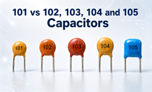
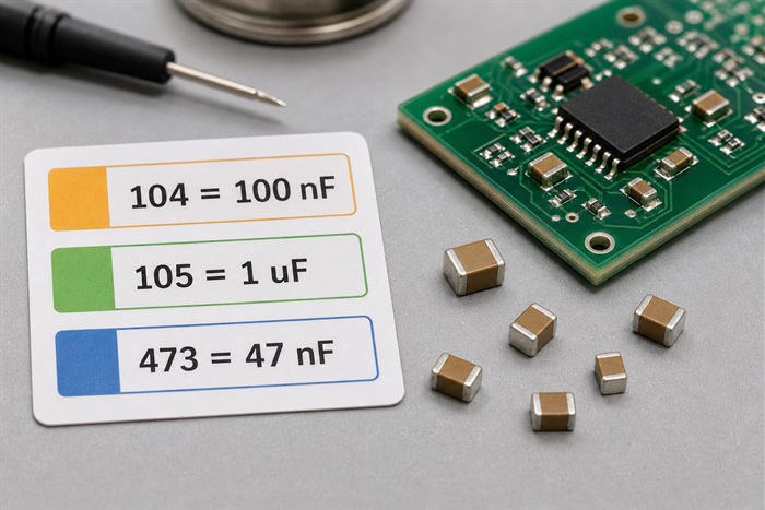
Many larger ceramic capacitors use a three-digit ceramic capacitor code. The first two digits are significant figures, and the third digit is the multiplier in picofarads. For example, 104 means 10 followed by four zeros in pF, which equals 100,000 pF, 100 nF, or 0.1 uF. A tolerance letter may also appear, such as J for 5%, K for 10%, and M for 20%.
| Code | Calculation | Capacitance Value | Typical PCB Use |
| 101 | 10 x 10^1 pF | 100 pF | RF tuning, high-frequency signal paths, timing networks |
| 102 | 10 x 10^2 pF | 1 nF | Signal filtering, small coupling networks |
| 103 | 10 x 10^3 pF | 10 nF | Local filtering and low-current decoupling |
| 104 | 10 x 10^4 pF | 100 nF, 0.1 uF | Common IC decoupling capacitor |
| 105 | 10 x 10^5 pF | 1 uF | Local bulk decoupling and small power rails |
| 106 | 10 x 10^6 pF | 10 uF | Power input filtering, regulator output support |
Very small SMD ceramic capacitors often have no marking at all. In that case, the only reliable identification path is the BOM, schematic reference designator, assembly drawing, pick-and-place file, and approved manufacturer part number. During PCB assembly, this is why complete BOM data matters more than visual inspection alone.
How Do You Calculate Ceramic Capacitor Value?
To calculate ceramic capacitor value from a three-digit code, read the value in pF first, then convert to nF or uF when needed. The conversion is simple: 1,000 pF equals 1 nF, and 1,000 nF equals 1 uF. This matters because schematics, BOMs, datasheets, and distributor listings may express the same part in different units.
| Displayed Value | Equivalent Value | Common Meaning | Procurement Note |
| 100,000 pF | 100 nF / 0.1 uF | Typical decoupling value | Confirm voltage and dielectric, not just capacitance |
| 1,000,000 pF | 1 uF | Local rail support | Check DC bias derating for MLCC parts |
| 10,000,000 pF | 10 uF | Bulk ceramic capacitance | Package size and voltage rating can change actual capacitance |
For engineering review, the nominal ceramic capacitor value is only the starting point. In Class 2 MLCCs, effective capacitance can drop under DC bias, temperature change, and aging. A 10 uF part may not behave like 10 uF in circuit if the voltage rating, package size, and dielectric are poorly chosen.
Which PCB Capacitor Types Should You Compare?
PCB capacitor types should be compared by function, not only by price. Ceramic capacitors are excellent for compact high-frequency decoupling, but electrolytic, tantalum, polymer, and film capacitors may be better for larger bulk energy storage, low leakage, pulse handling, or long-life power filtering.
| Capacitor Type | Strength on PCB | Limitation | Typical Use |
| Ceramic MLCC | Small size, low ESL, good high-frequency behavior | DC bias, cracking risk, dielectric variation | Decoupling, filtering, timing, coupling |
| Aluminum electrolytic | High capacitance at lower cost | Polarized, larger, higher ESR, lifetime limits | Input/output bulk capacitance |
| Tantalum or polymer | Stable bulk capacitance in compact packages | Cost, derating, sourcing and failure-mode concerns | Power rails, compact products, controlled ESR needs |
| Film capacitor | Low loss and good stability | Larger package size | Power, audio, snubber, precision circuits |
For most digital PCB assemblies, the practical solution is not one capacitor family. A board may use small ceramic capacitors close to ICs, one or more larger ceramic or polymer capacitors near regulators, and electrolytic or film capacitors where energy storage, ripple current, or voltage stress requires a different technology.
What Parameters Matter for SMD Ceramic Capacitors?
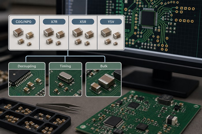
The most important ceramic capacitor parameters are capacitance value, tolerance, rated voltage, dielectric class, package size, temperature range, DC bias behavior, ESR, ESL, and manufacturer part number. For PCBA production, the package and termination finish are also critical because they affect placement, solder joint quality, and approved substitutions.
| Parameter | Why It Matters | Buyer or Engineer Check |
| Dielectric | C0G/NP0 is stable; X7R/X5R offers higher capacitance but more variation | Use stable dielectrics for timing, RF, and precision analog circuits |
| Rated voltage | Higher voltage margin reduces stress and DC bias loss | Avoid choosing only the minimum rated voltage for high-capacitance MLCCs |
| Package size | Smaller packages save space but may have stronger capacitance loss under bias | Confirm 0201, 0402, 0603, or 0805 against assembly capability and design risk |
| Tolerance | Timing and filter circuits may need tighter control than decoupling circuits | Do not replace a 5% part with 20% unless the circuit allows it |
| MPN | Different vendors with the same value may behave differently under bias | List approved alternatives in the BOM before production |
EBest Circuit (Best Technology) can review BOM and assembly files during PCBA quotation, but the fastest review happens when the customer provides full part numbers, reference designators, package sizes, tolerance, voltage ratings, and any approved substitute list at the beginning.
Where Should Ceramic Capacitors Be Placed on a Board?
Ceramic capacitors used for decoupling should be placed close to the power and ground pins of the device they support. The goal is to create a short current loop with low inductance. In dense boards, this may require careful via placement, a nearby ground plane connection, and enough clearance for pick-and-place and reflow soldering.
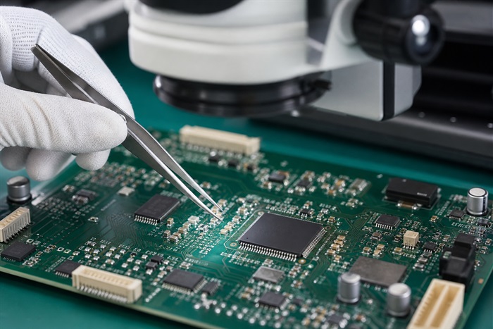
For power rails, engineers often combine multiple capacitor values to cover different frequency ranges, but placement still controls performance. A 100 nF ceramic capacitor far from the IC pin is less useful than the same capacitor located directly beside the pin with a short ground return. For high-current or high-speed boards, the PCB stackup, plane design, and component side also affect the final result.
If a board uses fine-pitch ICs, very small ceramic capacitors, or double-sided assembly, DFM review should check land pattern size, solder mask clearance, component spacing, tombstoning risk, and whether the part can be inspected after assembly. For standard FR4 PCB projects, these layout details can matter as much as the capacitor value itself.
What Should Buyers Check Before PCBA Assembly?
Before PCBA assembly, buyers should confirm that every ceramic capacitor in the BOM matches the schematic, PCB footprint, voltage margin, dielectric requirement, and sourcing plan. This prevents common problems such as wrong package size, wrong capacitance unit, missing no-load notes, unavailable MPNs, and unauthorized part substitution.
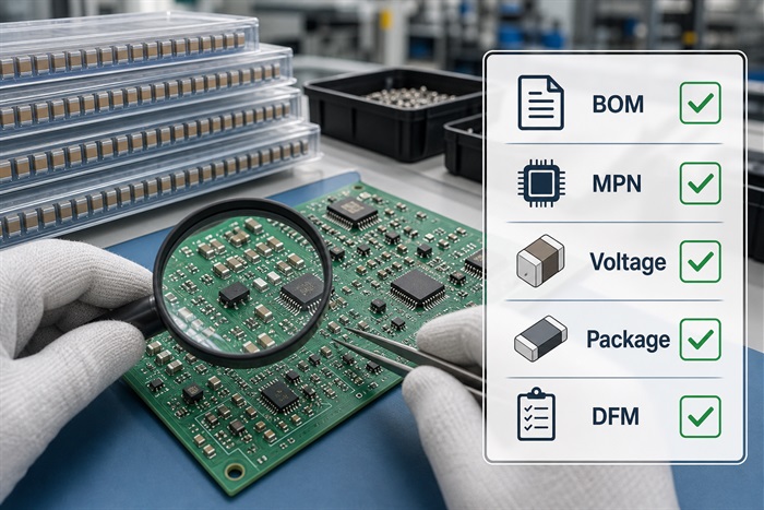
- Provide schematic, Gerber files, BOM, centroid file, assembly drawing, and any special capacitor notes.
- Mark DNI or DNP parts clearly so the assembly team does not place optional capacitors by mistake.
- Confirm whether no-marking SMD capacitors can be verified through reels, labels, and traceability records.
- Check if substitutes must match dielectric, voltage, tolerance, package, height, and temperature range.
- Review small packages such as 0201 and 01005 against assembly capability and inspection requirements.
For prototype builds, a short engineering review can prevent costly delays. For production builds, the same review helps lock approved vendors, reduce purchasing substitutions, and keep the assembly process repeatable. If the project is still early, a PCB prototype build is a practical way to validate BOM, layout, and component placement before larger volume purchasing.
FAQ
Are ceramic capacitors polarized?
Most ceramic capacitors used on PCBs are non-polarized, so they do not have a positive or negative side like electrolytic capacitors. The footprint and placement still need to match the package and assembly drawing.
What does 104 mean on a ceramic capacitor?
104 means 10 x 10^4 pF, which equals 100,000 pF, 100 nF, or 0.1 uF. It is one of the most common values used for IC decoupling on PCB assemblies.
Why do some SMD ceramic capacitors have no marking?
Small SMD ceramic capacitors often have no printed code because there is not enough body area. Identification should come from the BOM, reel label, reference designator, assembly files, and manufacturer traceability.
Is X7R better than Y5V for PCB assembly?
X7R is usually more stable than Y5V over temperature and is often preferred for general decoupling when space and cost allow. Y5V may provide high nominal capacitance at low cost but can lose much more capacitance in real operating conditions.
When should C0G or NP0 ceramic capacitors be used?
C0G or NP0 capacitors are suitable for timing, resonant, RF, precision analog, and low-distortion circuits because their capacitance is much more stable than Class 2 dielectrics. They usually offer lower capacitance values and may cost more for a given package size.
Can a ceramic capacitor be replaced with the same value from another supplier?
Only when the substitute matches the electrical and mechanical requirements of the circuit. The review should include capacitance, tolerance, voltage, dielectric, package, height, temperature range, DC bias behavior, and approved manufacturer status.
Where should decoupling ceramic capacitors be placed?
They should be placed as close as practical to the IC power and ground pins they support, with a short return path to ground. Poor placement can reduce performance even when the value is correct.
What files are needed for ceramic capacitor PCBA review?
The assembly team should receive Gerber files, schematic, BOM, centroid file, assembly drawing, special notes, and approved alternative part lists. For capacitor-heavy boards, reference designator clarity is especially important.
Do ceramic capacitors fail during soldering?
They can be damaged by board flex, thermal shock, poor land pattern design, excessive solder volume, or handling stress. DFM review and controlled reflow profiles help reduce cracking and solder-joint risk.
How can EBest Circuit support ceramic capacitor PCB projects?
EBest Circuit (Best Technology) can support PCB fabrication, component sourcing, BOM review, SMT assembly, prototype builds, and engineering communication for boards that use SMD ceramic capacitors and other passive components.
Conclusion
Ceramic capacitors are small parts, but they influence PCB stability, noise control, sourcing accuracy, and assembly yield. A good review should connect ceramic capacitor code, value, symbol, dielectric, voltage rating, package, placement, and BOM traceability instead of checking capacitance alone.
If you are preparing a PCB or PCBA project with SMD ceramic capacitors, EBest Circuit (Best Technology) can help review your fabrication files, BOM, assembly requirements, and quotation details. Send your files or questions to sales@bestpcbs.com or contact the team through the BestPCBs contact page.