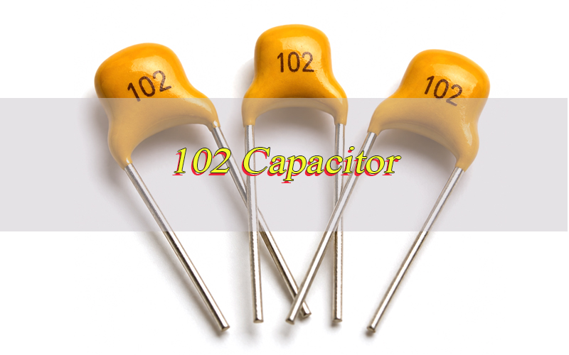
A 102 capacitor equals 1000 pF, 1 nF, or 0.001 µF. The number “102” is a standard capacitor code, where “10” is the base number and “2” means two zeros are added in picofarads.
This guide explains the 102 capacitor value, capacitor 102 marking, ceramic capacitor 102 value, datasheet checks, common types, circuit use, replacement rules, failure problems, cost factors, and supplier selection.
What Is a 102 Capacitor?
A 102 capacitor is a capacitor marked with the code “102,” and its capacitance is 1000 pF. This value is also written as 1 nF or 0.001 µF, depending on the unit format used in a datasheet, BOM, or repair document.
The part is commonly found in ceramic disc capacitors, SMD ceramic capacitors, and small signal filtering circuits. Because the value is small, it is usually used for high-frequency noise control, signal coupling, bypassing, timing, and EMI reduction.
The key point is simple: 102 is a capacitance code, not a voltage rating or part number. Other specifications must still be checked before replacement or bulk purchasing.
What Is the 102 Capacitor Value in pF, nF and µF?
The 102 capacitor value is 1000 pF, 1 nF, or 0.001 µF. These three values are exactly the same capacitance expressed in different units.
| Code | pF | nF | µF |
|---|---|---|---|
| 102 | 1000 pF | 1 nF | 0.001 µF |
This conversion matters because different documents may use different units. A datasheet may list 1 nF, a BOM may show 0.001 µF, and the physical capacitor may be marked 102.
When checking capacitor value 102, always convert the unit before replacement. A wrong unit reading can lead to incorrect filtering, unstable timing, or circuit failure.
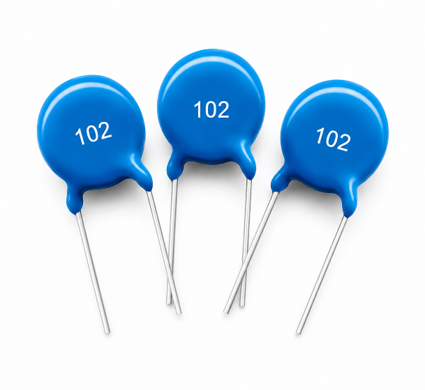
How Do You Read the 102 Capacitor Code?
The 102 capacitor code is read with the three-digit capacitor marking rule. The first two digits are the significant number, and the third digit is the multiplier based on picofarads.
For capacitor code 102, the first two digits are 10. The third digit is 2, which means two zeros are added. So the calculation is 10 × 100 pF = 1000 pF.
In other words, capacitor marking 102 means 1000 pF, not 102 pF. This same rule applies to many common ceramic capacitor codes, such as 101, 103, and 104. Therefore, code reading is the first step before any replacement decision.
What Does 102 Marking Mean on a Ceramic Capacitor?
The 102 marking on a ceramic capacitor means the ceramic capacitor value is 1000 pF. It only confirms capacitance and does not automatically confirm voltage rating, tolerance, dielectric material, package size, or safety certification.
A 102 ceramic capacitor may also include extra letters or numbers. For example, 102K usually means 1000 pF with ±10% tolerance, while markings such as 1kV or 2kV show voltage rating.
This distinction is important during repair and purchasing. A capacitor 102 may have the same capacitance as another part but a different voltage rating or material. For reliable selection, the marking should be checked together with the datasheet and original circuit requirement.
102 Capacitor Datasheet Overview
A 102 capacitor datasheet confirms the real specifications behind the 102 marking. The printed code only shows capacitance, while the datasheet confirms whether the part fits the circuit, soldering process, voltage stress, and quality requirement.
| Parameter | What to Check | Selection Note |
|---|---|---|
| Capacitance | 1000 pF / 1 nF / 0.001 µF | Confirms the real 102 capacitor value |
| Voltage Rating | 50V, 100V, 1kV, 2kV, or project rating | Use equal or higher voltage than the original part |
| Tolerance | J, K, M, or custom tolerance | Tighter tolerance is better for timing and precision circuits |
| Dielectric | C0G/NP0, X7R, Y5V, Z5U | C0G/NP0 is more stable; X7R fits general filtering |
| Package | SMD, disc, radial, through-hole | Must match PCB pads, lead pitch, and assembly method |
| Temperature Range | Operating and storage temperature | Important for industrial, automotive, and outdoor electronics |
| Insulation Resistance | Leakage and insulation data | Critical for high-voltage and low-leakage circuits |
| Dissipation Factor | Loss performance | Lower loss is better for high-frequency signal circuits |
| Solderability | Reflow, wave soldering, or hand soldering | Must match the actual PCB assembly process |
| Compliance | RoHS, REACH, UL, customer standard | Required for regulated markets and export projects |
| Packing | Tape-and-reel, bulk, ammo pack, cut tape | Affects SMT automation, storage, and production efficiency |
For high-voltage, repair, or mass production projects, the datasheet should be checked before sample approval, BOM locking, and bulk purchasing.
What Are Common Types of 102 Capacitors?
A 102 capacitor can appear in different package types and voltage ratings, depending on the PCB design, assembly method, and working voltage.
Common types include:
- Ceramic capacitor type for filtering, bypassing, and signal circuits.
- Disc capacitor type for through-hole PCB assembly and high-voltage use.
- SMD capacitor type for compact electronics and automated SMT production.
- 1kV rated type for medium high-voltage filtering and coupling.
- 2kV rated type for stronger insulation and higher-voltage applications.
- Safety-related ceramic type for approved protection circuits.
Although these parts may share the same capacitance, they are not always interchangeable. The correct type depends on voltage stress, board space, soldering process, dielectric stability, and safety requirements.
How Does a 102 Capacitor Work in a Circuit?
A 102 capacitor stores and releases a small electrical charge to control noise, signal flow, and voltage changes. Because its capacitance is only 1 nF, it responds well to high-frequency behavior rather than large energy storage.
In a circuit, it may block DC while allowing certain AC signals to pass. It may also shunt high-frequency noise to ground, stabilize switching signals, or help form an RC timing network with a resistor.
For example, a ceramic part with this value may be placed near an IC pin, sensor line, oscillator circuit, power stage, or communication interface. Its small value makes it useful when the circuit requires fast response and limited capacitance loading.
What Is the Use of 102 Capacitor?
A 102 capacitor is commonly used in circuits that require small capacitance and high-frequency response. It appears in both consumer electronics and industrial PCB assemblies.
Common uses include:
- Signal coupling in audio, sensor, and communication circuits.
- Noise filtering in power lines and control boards.
- High-frequency bypassing near ICs and switching devices.
- RC timing circuits where 1 nF capacitance is suitable.
- EMI reduction in selected signal and power paths.
- High-voltage filtering when using properly rated 1kV or 2kV ceramic parts.
- Industrial control boards where stable small-value ceramic capacitors are required.
What Are the Advantages and Limitations of a 102 Capacitor?
A 102 capacitor is useful for compact filtering and signal control, but it has clear limitations because its capacitance is small.
Main advantages include:
- Small size for compact PCB layout.
- Fast response for high-frequency noise control.
- Low cost for mass production.
- Wide availability in ceramic disc and SMD packages.
- Multiple voltage options for low-voltage and high-voltage circuits.
- Easy identification through the standard code.
Main limitations include:
- Low capacitance, so it cannot replace larger capacitors.
- Material sensitivity if low-grade ceramic dielectric is used.
- Possible capacitance drift caused by temperature, aging, or DC bias.
- Replacement risk if voltage rating and package are ignored.
- Limited energy storage compared with electrolytic or film capacitors.
How Can You Replace a 102 Capacitor Correctly?
A 102 capacitor replacement should match capacitance first, then confirm voltage rating, tolerance, dielectric material, package size, and circuit position. Wrong replacement may cause unstable filtering, changed timing, leakage, or early failure.
Step 1: Confirm the original marking.
Check whether the old part is marked 102, 102K, capacitor 102 1kV, capacitor 102 2kV, or another extended code. The 102 marking confirms 1000 pF / 1 nF / 0.001 µF, but other letters and numbers may show tolerance or voltage rating.
Step 2: Check the circuit function.
Identify whether the capacitor is used for filtering, coupling, bypassing, EMI reduction, timing, or high-voltage protection. The same capacitance value may require different voltage ratings or dielectric materials in different circuit positions.
Step 3: Match the voltage rating.
Choose a replacement with the same or higher voltage rating than the original part. For example, a lower-voltage capacitor should not replace a 1kV or 2kV part in a high-voltage circuit.
Step 4: Match tolerance and dielectric material.
Check whether the original part uses J, K, M tolerance or a specific dielectric such as C0G/NP0, X7R, Y5V, or Z5U. Precision, timing, RF, and signal circuits usually require more stable dielectric material.
Step 5: Confirm package and lead spacing.
Match the SMD size, disc diameter, radial shape, lead pitch, and PCB pad layout. Even if the capacitance is correct, the part may not fit the board or pass assembly inspection if the package is wrong.
Step 6: Install and inspect the replacement.
After soldering, check the solder joints, body cracks, pad condition, and component position. Then measure capacitance when possible and power the circuit carefully to confirm stable operation.
For repair, sample builds, or mass production, the safest replacement is the same value with equal or higher voltage rating, matching package, and approved datasheet support.
What Should Be Checked Before Buying 102 Capacitors?
Before buying 102 capacitors, the buyer should confirm electrical specifications, mechanical fit, compliance, and supply stability. A low price is not useful if the wrong part causes rework or production delay.
Key checks include:
- Capacitance value: confirm 1000 pF, 1 nF, or 0.001 µF.
- Voltage rating: confirm 50V, 100V, 1kV, 2kV, or the required rating.
- Tolerance: select J, K, M, or the tolerance required by the circuit.
- Package: confirm SMD size, disc diameter, radial form, or lead pitch.
- Dielectric: match C0G/NP0, X7R, Y5V, or Z5U according to stability needs.
- Datasheet: check the approved datasheet before final order.
- Compliance: confirm RoHS, REACH, UL, or project-specific standards.
- Packing: choose tape-and-reel, bulk, ammo pack, or cut tape.
For OEM and ODM manufacturing, the approved BOM should list exact specifications instead of only writing “102 capacitor.”
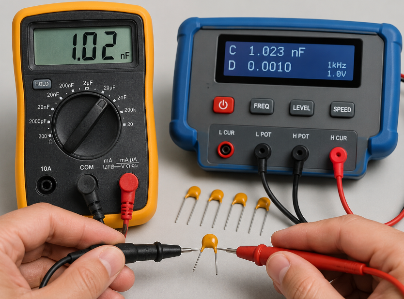
How to Test a 102 Capacitor?
Testing a 102 capacitor should confirm capacitance value, leakage risk, physical condition, and circuit stability. Because the value is only 1000 pF / 1 nF / 0.001 µF, a normal multimeter may not measure it accurately unless it has a small-capacitance range.
Step 1: Inspect the capacitor body.
Check for cracks, burn marks, broken leads, oxidation, discoloration, or damaged solder joints. Ceramic capacitors may fail after mechanical stress, overheating, or PCB bending, even when the marking still looks normal.
Step 2: Measure capacitance with an LCR meter.
Use an LCR meter or capacitance meter to check whether the reading is close to 1000 pF. The acceptable range depends on tolerance, such as ±5%, ±10%, or ±20%.
Step 3: Check for short circuit.
Use resistance mode to confirm the capacitor is not shorted. A shorted capacitor may show very low resistance and can cause power supply protection, signal failure, overheating, or circuit shutdown.
Step 4: Check leakage or insulation resistance.
For high-voltage types, leakage and insulation resistance are important. A capacitor may pass a basic capacitance test but still fail under voltage stress if the dielectric insulation is damaged.
Step 5: Compare with circuit symptoms.
If the circuit has noise, unstable signal, failed startup, timing error, or repeated fuse/power shutdown, compare the test result with the circuit function. A wrong value or damaged capacitor may affect performance even if it is not fully shorted.
Step 6: Replace and verify when uncertain.
For low-cost ceramic capacitors, replacement is often faster than repeated testing. After replacement, check solder joints, power behavior, signal stability, and measured output to confirm the fault is solved.
For repair, incoming inspection, or production quality control, the best testing method is visual inspection plus LCR measurement, followed by insulation or voltage testing when the capacitor works in a high-voltage circuit.
What Common Failure Problems Occur with 102 Capacitors?
A 102 capacitor can fail because of overvoltage, ceramic cracking, overheating, poor soldering, moisture, or incorrect replacement. These problems are common in repair work and mass production.
Common failure problems include:
- Open circuit caused by cracked ceramic body or damaged internal electrode.
- Short circuit caused by dielectric breakdown or voltage overstress.
- Capacitance drift caused by temperature change, aging, or DC bias.
- Leakage current caused by insulation damage or contamination.
- Poor solder joint caused by oxidation, wrong soldering profile, or pad pollution.
- Wrong substitution when the value is confused with 102 pF or 0.01 µF.
- Mechanical stress failure caused by PCB bending or rough handling.
Reliable sourcing, correct derating, controlled soldering, and incoming inspection can greatly reduce these risks.
How Do Cost Factors Affect 102 Capacitor Selection?
The cost of a 102 capacitor is affected by voltage rating, dielectric material, tolerance, package, certification, and order quantity. A standard low-voltage SMD type is usually cheaper than a high-voltage ceramic disc type.
For example, a 1kV or 2kV ceramic capacitor usually costs more because it requires stronger dielectric insulation and larger physical spacing. C0G/NP0 parts may also cost more than general-purpose ceramic materials because they provide better capacitance stability.
In bulk purchasing, the lowest unit price may increase total cost if it causes unstable quality, assembly defects, or field returns. A better strategy is to compare performance, compliance, delivery stability, and approved alternatives together.
How to Choose a Reliable 102 Capacitor Supplier?
A reliable 102 capacitor supplier should provide correct value confirmation, datasheets, compliance support, stable quality, and engineering communication. This is especially important for OEM production, ODM projects, PCB assembly, and long-term supply.
Good supplier selection should focus on:
- Correct marking review to avoid confusion between 102, 103, and 104.
- Datasheet support for voltage rating, tolerance, dielectric, and package.
- Batch consistency for capacitance and soldering performance.
- Compliance documents for RoHS, REACH, UL, or customer requirements.
- Alternative part support when the original capacitor is unavailable.
- Failure review ability for cracked, shorted, or drifting capacitors.
- Global supply experience from a real China source factory without false overseas branches.
For overseas buyers, direct factory communication helps reduce sourcing mistakes, sample approval delays, and repeated BOM revisions.
FAQs About 102 Capacitor
Q1: Is a 102 capacitor 102 pF?
A1: No. A 102 capacitor is 1000 pF, not 102 pF. The first two digits are “10,” and the third digit “2” means two zeros are added. Therefore, 102 means 10 × 100 pF = 1000 pF.
Q2: What is the 102 capacitor value in microfarad?
A2: The value in microfarad is 0.001 µF. The same capacitance can also be written as 1000 pF or 1 nF. These are only different unit formats for the same capacitor value.
Q3: What does 102K mean on a capacitor?
A3: 102K usually means 1000 pF with ±10% tolerance. The “102” shows capacitance, and “K” shows tolerance. If voltage is not printed on the body, check the datasheet, BOM, or original circuit information before replacement.
Q4: Can I replace a 102 capacitor with a 103 capacitor?
A4: Usually no. A 102 capacitor is 1 nF, while a 103 capacitor is 10 nF. That is a 10 times higher value. Using 103 instead of 102 may change filtering, timing, signal response, or circuit stability.
Q5: Can I use a higher-voltage 102 capacitor?
A5: Yes, a higher-voltage part can often replace a lower-voltage one if the package size, lead spacing, dielectric type, and board clearance are suitable. For example, a 2kV part may replace a 1kV part when space allows.
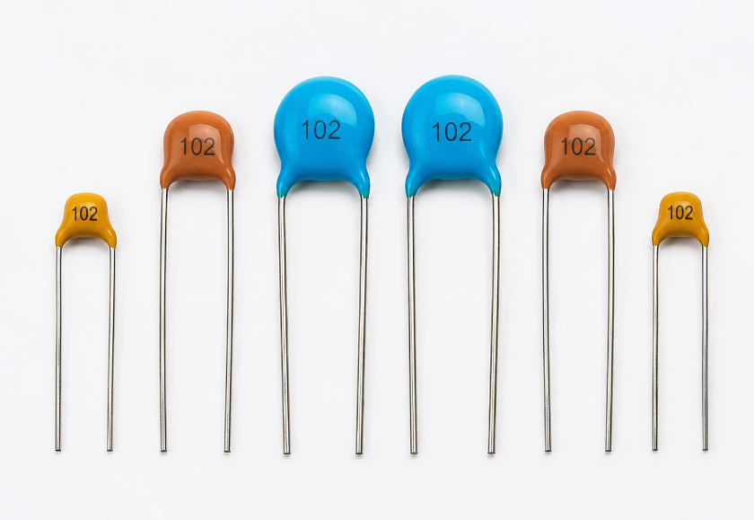
Q6: Why does a 102 ceramic capacitor look different from another 102 capacitor?
A6: Two capacitors with the same 1 nF value may look different because of voltage rating, dielectric material, tolerance, and package type. A 2kV ceramic part is usually larger than a low-voltage SMD capacitor.
Q7: What should I check in a 102 capacitor datasheet?
A7: Check capacitance, voltage rating, tolerance, dielectric material, package size, temperature range, insulation resistance, and compliance. The datasheet confirms whether the part fits the circuit, while the marking only confirms capacitance.
Q8: Is a 102 capacitor polarized?
A8: Most ceramic capacitors with this value are non-polarized and can be installed in either direction. However, the actual circuit position, package type, and product design should still be reviewed before replacement or assembly approval.
Q9: How do I test a 102 capacitor with a multimeter?
A9: A normal multimeter may not measure small capacitance accurately. Use an LCR meter or capacitance meter. The expected reading should be around 1000 pF, with variation depending on tolerance such as ±5%, ±10%, or ±20%.
Q10: Why does a 102 capacitor fail in a power supply?
A10: Common causes include overvoltage, heat, poor derating, soldering stress, ceramic cracking, and wrong replacement. In high-voltage circuits, using a lower-voltage substitute may cause leakage, breakdown, or short-circuit failure.
Q11: What does 102 mean on an SMD capacitor?
A11: If an SMD capacitor is marked 102, it usually means 1000 pF / 1 nF. Many small SMD capacitors have no visible marking, so the reel label, BOM, or component datasheet should be checked before use.
Q12: What tolerance should I choose for a 102 capacitor?
A12: Common tolerance codes include J = ±5%, K = ±10%, and M = ±20%. Precision circuits should use tighter tolerance, while general filtering circuits may accept wider tolerance if the design allows it.
Q13: Can a 102 capacitor be used for EMI filtering?
A13: Yes, this value can help reduce high-frequency noise. However, EMI performance also depends on placement, grounding, voltage rating, safety approval, and PCB layout. For mains-related circuits, use the correct safety-rated capacitor.
Q14: What should I send to a supplier when buying 102 capacitors?
A14: Send the value 1 nF, voltage rating, tolerance, package type, dielectric material, quantity, compliance requirement, and application. For PCB assembly, also provide the BOM, PCB files, approved manufacturer list, and sample requirement.
Q15: Is 102 capacitor suitable for mass production?
A15: Yes, this component value is common in mass production. For stable production, confirm approved manufacturer, package size, voltage rating, tolerance, packing method, datasheet, and incoming quality inspection standard before bulk purchasing.
Conclusion
A 102 capacitor equals 1000 pF, 1 nF, or 0.001 µF. The code is easy to read, but correct selection depends on voltage rating, tolerance, dielectric material, package size, datasheet confirmation, soldering process, and real circuit function.
For replacement, match the original capacitance first, then confirm voltage and package details. For purchasing, avoid selecting parts by price alone. Stable quality, approved datasheets, batch consistency, and engineering support are more important for OEM manufacturing, ODM production, sample development, and mass production.
If you are looking for reliable component sourcing and PCB assembly service, please contact EBest Circuit for technical support and a quote: sales@bestpcbs.com.