Understanding factors to consider when choosing ceramic substrates is critical for device performance and reliability. This guide covers all essential factors to consider when choosing ceramic substrates for professional engineering applications.
Ceramic Substrates
What are the key factors to consider when choosing ceramic substrates?
The most important factors include thermal, electrical, mechanical, material, and application compatibility.
These elements directly decide performance, stability, and service life.
Selecting correctly avoids failures in high‑demand environments.
Thermal conductivity and thermal expansion
Dielectric constant and insulation performance
Mechanical strength and structural stability
Material type and manufacturing compatibility
Quality, supply chain, and delivery
How do material properties affect ceramic substrate selection?
Material properties form the foundation of ceramic substrate performance.
Mismatched properties lead to overheating, signal loss, or mechanical breakage.
Each parameter must align with your application needs.
Thermal conductivity requirements
Higher thermal conductivity improves heat dissipation for high‑power devices.
It keeps components cool and extends service life.
This is non‑negotiable for power and automotive electronics.
Dielectric and insulation performance
Dielectric constant impacts signal integrity.
High insulation prevents leakage in high‑voltage systems.
Low dielectric loss improves energy efficiency.
Which thermal factors matter most for ceramic substrates?
Thermal performance ensures long‑term stability under load and temperature cycles.
Poor thermal design causes cracking, warping, and early failure.
Thermal matching is vital for reliable assembly.
Coefficient of thermal expansion (CTE) matching
Thermal cycling stability
High temperature resistance
Heat dissipation path design
Compatibility with thermal interface materials
How to match electrical requirements for ceramic substrates?
Electrical properties protect circuits and ensure signal quality.
They prevent interference and breakdown in demanding environments.
Correct values keep systems safe and stable.
Insulation resistance
High insulation resistance supports high‑voltage applications.
It reduces risk of short circuits and electrical failures.
Critical for power electronics and industrial controls.
Dielectric loss
Low dielectric loss improves efficiency in high‑frequency devices.
It reduces heat from signal transmission.
Ideal for communication and server equipment.
What mechanical standards should ceramic substrates meet?
Mechanical strength prevents breakage during production and use.
It supports handling, assembly, and harsh environments.
Strong substrates maintain dimensional stability.
Bending strength
Fracture toughness
Hardness and wear resistance
Dimensional accuracy
Thermal shock resistance
How to compare common ceramic substrate materials
How to compare common ceramic substrate materials?
The table below helps you choose based on performance and application.
Material
Thermal Conductivity (W/m·K)
Dielectric Constant
Typical Applications
Alumina (Al₂O₃)
20–30
9.8
Consumer electronics, LED
Aluminum Nitride (AlN)
170–230
8.8
Automotive, power electronics
Silicon Nitride (Si₃N₄)
20–90
7.0
High‑power devices
Zirconia (ZrO₂)
2–3
25.0
Medical devices, sensors
Which industries use ceramic substrates most widely?
Ceramic substrates perform best in four high‑growth industries.
Automotive electronics
AlN substrates handle heat in EV power modules.
They withstand vibration and extreme temperatures.
Ensure stable performance in motor controls.
Medical electronics
High‑purity alumina offers biocompatibility and insulation.
It meets strict medical standards for monitoring devices.
Safe for long‑term implantable and diagnostic tools.
LED & power electronics
Ceramic substrates improve heat dissipation for LEDs.
They extend lifespan and boost brightness.
Widely used in industrial and outdoor lighting.
Aerospace & industrial control
Special ceramics resist extreme temperatures and corrosion.
They meet aerospace reliability standards.
Stable in automation and harsh factory environments.
How to ensure processing compatibility of ceramic substrates?
Processing compatibility lowers production difficulty and cost.
Good metallization and bonding support strong assembly.
Stable processing ensures consistent yields.
Machinability
Metal layer adhesion
Solderability and bonding strength
Compatibility with standard PCB processes
Tolerance control
How to judge ceramic substrate quality and reliability?
Quality control prevents inconsistent performance and failures.
Certified materials and testing ensure long service life.
Reliable substrates reduce maintenance and replacement cost.
Raw material purity
Dimensional accuracy
Thermal cycle testing
Insulation and voltage testing
Compliance with international standards
Why supply chain & delivery matter for ceramic substrates?
Stable supply avoids production delays and shortages.
On‑time delivery keeps projects on schedule.
Consistent quality supports mass production.
Steady raw material supply
On‑time delivery capability
Full quality traceability
Professional technical support
Mass production capacity
Can ceramic substrates be customized for special uses?
Customization meets unique design and performance needs.
Tailored materials, sizes, and structures fit special equipment.
FAQ: Top questions about factors to consider when choosing ceramic substrates
What factors to consider when choosing ceramic substrates?
Key factors include thermal performance, electrical properties, mechanical strength, material type, quality, supply chain, and application compatibility.
Which ceramic substrate is best for high power?
Aluminum nitride (AlN) is best for high power due to ultra‑high thermal conductivity.
How to ensure thermal reliability of ceramic substrates?
Match thermal expansion coefficients and use high‑thermal‑conductivity materials.
What is the difference between AlN and alumina substrates?
AlN has much higher thermal conductivity; alumina offers cost‑effective general use.
Can ceramic substrates be used in medical devices?
Yes, high‑purity alumina is widely used for biocompatibility and stability.
How to select a reliable ceramic substrate supplier?
Check quality system, delivery stability, technical support, and supply chain.
Are ceramic substrates customizable for special applications?
Yes, materials, dimensions, and performance can be customized for specific needs.
Conclusion
All factors to consider when choosing ceramic substrates must be evaluated together.
The right choice improves performance, reliability, and product stability.
Professional selection supports long‑term success in high‑end electronics.
EBest provides premium ceramic substrates with stable supply, strict quality control, and professional support. For orders and inquiries, contact us at: sales@bestpcbs.com
Are you struggling with ECU boardissues like unclear diagnostics, difficult cleaning, or confusing reflashing? This guide provides clear, practical guidance for working with an ECU Board. It offers step-by-step instructions for cleaning, testing, diagnosis, reflashing, and more, all designed to ensure reliable operation and simplify maintenance. Just actionable tips to streamline processes and maintain optimal performance in automotive electronic systems.
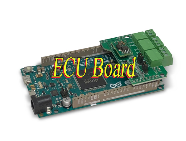
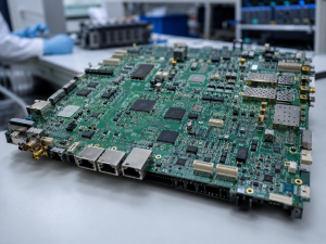
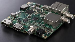
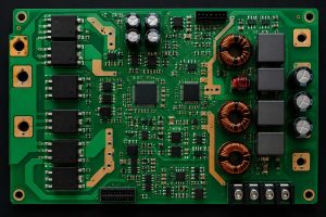
What is an ECU Board?
An ECU board (Electronic Control Unit Board) is a printed circuit board that serves as the central control unit for a vehicle’s electronic systems. It integrates car-grade microcontrollers, memory chips, power management circuits, and input/output interfaces to process real-time data from vehicle sensors, such as engine speed, temperature, and air flow and regulate critical components like fuel injectors and ignition systems. These components work together to enable precise control, including fuel injection timing and ignition advance, ensuring optimal engine performance. While designs vary by vehicle make and model to match specific performance needs, all ECU boards share the core goal of optimizing reliability, fuel efficiency, and overall vehicle functionality.
What Are Types of ECU Board Car?
Powertrain ECUs: Control engine (ECU/ECM), transmission (TCU/TCM), hybrid/electric motor (HCU/Motor ECU), and turbocharger systems.
Chassis & Safety ECUs: Manage ABS, electronic stability control (ESC), airbags, and tire pressure monitoring.
Body & Comfort ECUs: Regulate HVAC, power windows, seats, lighting, and keyless entry.
Infotainment & ADAS ECUs: Handle navigation, audio, connectivity (e.g., Bluetooth, GPS), and advanced driver-assistance features (e.g., adaptive cruise control, lane detection).
Energy Management ECUs: Oversee battery systems (BMS) in EVs/hybrids, charging processes, and regenerative braking.
What Does ECU Do?
Performance Optimization: Adjusts air-fuel ratios, ignition timing, and fuel injection for peak efficiency and power output.
Emissions Control: Reduces harmful exhaust emissions via catalytic converter coordination and real-time adjustments.
System Integration: Communicates with other ECUs via protocols like CAN, LIN, or Ethernet to synchronize vehicle subsystems (e.g., engine-transmission coordination).
Adaptive Capabilities: Uses machine learning/AI in modern ADAS to process sensor data (cameras, radar) for autonomous decisions (e.g., emergency braking, lane-keeping).
Diagnostic Support: Triggers warning lights and stores error codes for troubleshooting, enabling quick repairs via diagnostic tools.
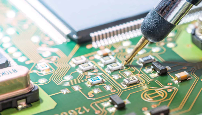
How to Clean ECU Board?
Cleaning anECU board is critical to prevent short circuits and signal interference, issues that cause 30% of ECU malfunctions. Even small debris (as small as 0.1mm) or oil residue can disrupt component connections. Below are step-by-step instructions with precise data for safe, effective cleaning:
Step 1: Power Off and Disassemble
Disconnect the board from the vehicle’s power supply and remove it from its housing. Wait 4-6 minutes (standard for 12V automotive ECUs) to fully discharge capacitors, this prevents electrical arcing that can damage 80% of sensitive microcontrollers on the board. Label connectors before removal to avoid misalignment during reassembly.
Step 2: Choose the Right Cleaner
Optimize for 90-99% isopropyl alcohol (70-80% concentrations leave 5-10% moisture residue, increasing corrosion risk) or a dedicated electronic circuit cleaner (meets IPC-J-STD-001 standards). Avoid water, bleach, or ammonia-based cleaners—they corrode solder joints and reduce component lifespan by up to 50%.
Step 3: Clean Gently
Use a soft-bristle brush (10-15mm bristle length) or compressed air set to 4-6 bar (3-5 bar is too low for stubborn dust; over 6 bar damages surface-mounted components) to remove loose debris. Wipe connectors and component pins with a lint-free cloth or cotton swab dipped in cleaner, spend 10-15 seconds per connector to remove oil residue that causes 40% of connection failures.
Step 4: Dry Thoroughly
Air-dry the board for 20-30 minutes in a well-ventilated area (15 minutes is insufficient for alcohol evaporation in humid environments). For faster drying, use low-temperature air (40-50°C; above 60°C warps PCB traces) with an airflow speed of 1.0-1.5 m/min. Verify no moisture remains with a multimeter (resistance reading ≥1MΩ between power and ground pins) before reassembly.
How to Get Gel off ECU Board?
Below are methods about how to get gel off ECU board:
1. Mechanical Scraping with Non-Conductive Tools: Use a plastic or soft-metal scraper (e.g., nylon spatula, bamboo stick) to gently pry off dried gel. Start from edges and work inward to avoid scratching circuits or components. Safety Tip: Wear anti-static gloves to prevent electrostatic discharge (ESD) damage.
2. Solvent-Based Dissolution: Apply isopropyl alcohol (≥90% concentration), acetone, or specialized electronic cleaning solvents (e.g., MG Chemicals 824-DW) to the gel using a cotton swab or soft brush. Let it soak for 5–10 minutes to soften the gel, then wipe gently with a microfiber cloth. Critical Note: Test solvents on a small, inconspicuous area first to check for material compatibility (e.g., avoid acetone on acrylic-coated boards).
3. Controlled Heat Application: Use a heat gun set to 120–150°F (49–66°C) or a hairdryer on low heat to warm the gel. Move the tool continuously to avoid localized overheating. Once softened, use tweezers or a soft brush to remove the gel. Warning: Exceeding 180°F (82°C) may damage solder joints or plastic components.
4. Ultrasonic Cleaning for Delicate Boards: Submerge the ECU board in an ultrasonic cleaner filled with distilled water or a mild solvent (e.g., deionized water + 5% isopropyl alcohol). Set the machine to 30–40kHz frequency for 3–5 minutes. Key Benefit: Ultrasonic waves dislodge gel without physical contact. Precaution: Remove batteries or sensitive components first to prevent water damage.
5. Adhesive Remover Gels for Stubborn Residue: Apply a commercial adhesive remover gel (e.g., Goo Gone, De-Solv-It) to the affected area. Let it sit for 15–20 minutes, then wipe with a lint-free cloth. Advantage: These gels are designed to break down sticky residues without harsh chemicals. Follow-Up: Clean the area thoroughly with isopropyl alcohol to remove any remover residue.
6. Freeze-and-Crack Method (For Non-Sensitive Components): Place the ECU board in a sealed plastic bag and freeze it for 2–3 hours. Remove and immediately tap the gel area gently with a soft hammer or the back of a screwdriver. The cold temperature makes the gel brittle, allowing it to crack and flake off. Limitation: Not recommended for boards with delicate surface-mount components.
7. Professional Rework Services: For high-value or warranty-protected ECU boards, consult a certified electronics repair service. Professionals use precision tools (e.g., rework stations, vacuum pens) and non-corrosive flux removers to safely extract gel without damaging circuits. Cost-Benefit: Minimizes risk of accidental damage and preserves warranty validity.
How to Identify Honda ECU Board?
Identifying a Honda ECU board is critical for accurate replacement and maintenance. Below are clear, actionable methods to identify it easily:
Check the Part Number: Every Honda ECU Board has a unique part number printed on the board surface or its housing. A common example is 37820-PNA-003. Always cross-verify this number with Honda’s official part database to confirm compatibility with the vehicle’s make and model. This step avoids incorrect replacements that lead to functionality issues.
Look for Branding: Most Honda ECU Boards feature the Honda logo or Honda Motor Co. printing on the board or housing. They often include branding from Honda’s trusted partners such as Denso. This branding is typically clear and visible, even after years of use, making it a quick identification marker.
Examine Connector Layout: Honda uses standardized connectors for its ECU Boards. Civic models usually have 32 pin connectors while Accord models commonly use 48 pin connectors. Match the connector count and shape to the vehicle’s specifications to ensure the ECU Board is compatible. This is especially useful for older Honda models where part numbers may be worn or unreadable.
Verify ECU Labeling: Many Honda ECU Boards have additional labeling indicating the PGM Fi system which is Honda’s proprietary electronic fuel injection system. This labeling confirms the board is designed for Honda’s specific engine management needs, further ensuring accuracy in identification.
How to Reflash ECU Circuit Board?
Reflashing an ECU board updates its firmware to fix bugs, improve performance, or adapt to modified components, critical for avoiding costly replacements. Below are actionable, detail-rich steps to ensure successful reflashing without damaging the board:
Step 1: Gather Tools
Use a reflashing tool compatible with the vehicle’s make and model, such as Honda HDS for Honda vehicles or tools supporting SAE J2534 standards for broader use. Ensure the laptop has the correct firmware file that matches the ECU part number to avoid corruption. Prepare a stable 12V external power supply. Unstable power causes 40% of reflashing failures, so avoid relying solely on the vehicle’s battery.
Step 2: Connect the Tool
Connect the reflashing tool to the vehicle’s OBD-II port. For problematic connections, remove the ECU and connect the tool directly to the board.Keep the vehicle’s engine off, engage the parking brake and turn off all accessories like lights and radio to reduce power draw. Confirm the power supply reads 12.4-12.7V for stable operation.
Step 3: Backup Firmware
Backup the ECU’s current firmware before proceeding. This step is essential to restore the board if reflashing fails or corrupts data. Save the backup file to the laptop and a secondary storage device. Label it with the vehicle’s VIN and ECU part number for easy retrieval. Verify the backup file size matches the ECU’s firmware size for added security.
Step 4: Flash New Firmware
Load the correct firmware file into the reflashing tool and follow on-screen prompts without skipping any steps. Keep the tool and laptop connected and powered on throughout the 5-10 minute process. Interruptions such as power loss or disconnection will brick the ECU and render it unusable. Do not adjust tool settings or run other software on the laptop during this time to avoid signal interference.
Step 5: Verify and Test
Disconnect the reflashing tool, turn off the vehicle’s ignition and wait 5 seconds before restarting. Use a diagnostic scanner to check for error codes. Clear any minor codes and retest. Verify key functions including engine start, sensor readings and actuator response to confirm the firmware update was successful. Reload the backup firmware and retry if the ECU fails to communicate.
How to Test ECU Board Car?
Testing a car ECU board ensures functionality before installation, reducing costly downtime. Use these methods:
Visual Inspection: Check for cracked solder joints, bulging capacitors, burnt components, or corrosion, common causes of ECU Board failure.
Voltage Testing: Use a multimeter to measure the ECU Board’s 12V power supply and ground connections. Stable voltage prevents erratic performance.
Signal Testing: Use an oscilloscope to check sensor input and actuator output signals. Ensure they fall within the manufacturer’s specified range.
Diagnostic Scanner Test: Connect an OBD-II scanner to read error codes. Clear codes, then test the vehicle to identify hidden ECU Board issues.
How to Diagnose an ECU Board?
Here are step-by-step guide for effective diagnosis:
Initial Visual Inspection
Check for physical damage (burnt components, corroded connectors, loose wires).
Verify all connections(OBD-II port, wiring harnesses) are secure and free of debris.
Look for water damage or moisture ingress, common in flood-affected vehicles.
Diagnostic Tool Scanning
Use a manufacturer-specific scanner (e.g., Toyota Techstream, BMW ISTA) or universal tool (SAE J2534) to read fault codes.
Prioritize active codes (current issues) over historical codes (past problems).
Clear codes after recording to distinguish intermittent vs. persistent issues.
Power & Ground Checks
Measure voltage at ECU power pins(should be 12–14V with ignition on).
Test ground connections for continuity (resistance <0.5Ω).
Poor grounding causes 30% of ECU failures, verify with multimeter.
Sensor & Actuator Testing
Use a multimeter to check sensor inputs (e.g., MAP, TPS, oxygen sensors) for correct voltage/signals.
Test actuators (fuel injectors, ignition coils) for proper operation via scan tool activation.
Compare live data against manufacturer specifications to identify deviations.
Software & Firmware Verification
Ensure the ECU software version matches the vehicle’s VIN and model year.
Update firmware only if a manufacturer-approved patch exists for known bugs.
Avoid unofficial firmware, risk of bricking the ECU.
Bench Testing (Advanced)
For suspected hardware faults, remove the ECU and test on a bench with a simulator.
Check components (capacitors, resistors) for proper values using a component tester.
Replace faulty components or send to a specialist for micro-soldering repairs.
How to Replace an ECU Board?
Replacing an ECU Board requires precision to ensure compatibility. Follow these steps:
Step 1: Select the Correct Replacement
Choose an ECU board that matches the vehicle’s make model and year. Ensure it meets original equipment quality standards to avoid compatibility issues.
Step 2: Disconnect the Old ECU
Turn off the vehicle power disconnect the battery and remove the old ECU Board. Note the position of each connector to prevent misconnection during reinstallation.
Step 3: Install the New ECU
Align the new ECU Board with its housing connect all connectors securely and fasten the board properly to prevent damage from vehicle vibration.
Step 4: Reconnect Power and Program
Reconnect the battery turn on the vehicle and program the new ECU Board using the vehicle’s VIN with a diagnostic scanner. Proper programming ensures the ECU works with the vehicle’s systems.
Step 5: Test the Vehicle
Test the vehicle including engine start acceleration and other key functions. Use a diagnostic scanner to check for error codes and confirm successful replacement.
Is ECU Board Repair Better Than Replacement?
When your ECU Board malfunctions, choosing between repair and replacement is a decision that directly impacts your time, cost and vehicle reliability. As someone who works with these components regularly, you want a solution that is cost-effective, efficient and minimizes downtime.
Repair is often the best choice for minor ECU circuit board issues. If the problem is loose solder, damaged connectors or faulty capacitors, repairing these specific parts is far more affordable than replacing the entire board. This is especially true if you have a rare or expensive ECU boards that is hard to source. Repairing also saves time on waiting for a new board to be delivered, getting your vehicle back in operation faster without compromising on functionality.
Replacement becomes necessary when the ECU circuit board has severe damage that cannot be fixed. If the microcontrollers are burnt, the PCB traces are cracked or the firmware is irreparably corrupted, repairing the board is not feasible. You should also consider replacement if the cost of repairs exceeds 70% of the price of a new board. A new ECU board ensures reliability and avoids the risk of repeated breakdowns that come with patching a severely damaged unit, which ultimately saves you time and money in the long run.
Would ECU Affects Cluster Board?
Yes, the ECU can affect the cluster board. The ECU shares critical data like speed, RPM, fuel level, and warnings with the cluster via vehicle networks such as CAN bus. It also controls cluster functions, including warning light activation and gauge display behavior.
A faulty ECU can disrupt this process. Common effects include erratic speedometer readings, frozen fuel gauges, false warning lights, or dimmed display screens. These issues compromise driver awareness and vehicle safety.
To diagnose, scan for ECU fault codes or communication errors using a diagnostic tool. Inspect CAN bus wiring for damage or corrosion. Test the cluster with a known-good unit to confirm if the ECU is the root cause. This streamlined approach ensures quick identification of ECU-related cluster problems, enabling efficient repairs and reliable vehicle operation.
Conclusion
By following the practical guidance outlined in this blog you can effectively maintain, troubleshoot and care for your vehicle’s central control unit ensuring consistent performance and avoiding costly downtime. Prioritizing quality components, regular maintenance and timely issue resolution will keep your vehicle’s electronic systems running smoothly for years to come.
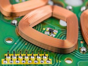
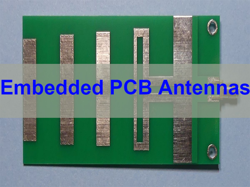
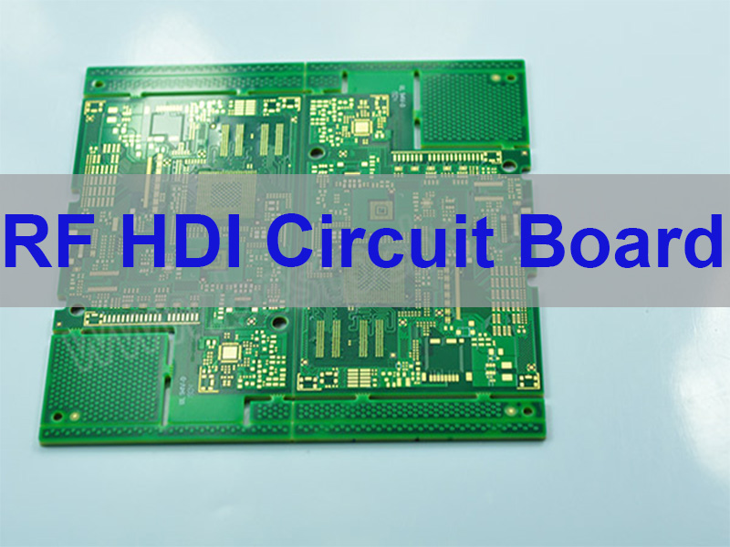
Embedded PCB Antennas are antenna structures directly integrated into the copper layers of a printed circuit board, enabling wireless communication without the need for external antenna components. This article explains how embedded PCB antennas work, their design principles, common structures such as 2.4 GHz embedded PCB antenna designs, and how manufacturers optimize antenna performance for wireless products.
Wireless connectivity has become fundamental in modern electronics. From IoT sensors and smart home devices to wearable technology and industrial control systems, engineers increasingly prefer antenna solutions that reduce product size, simplify assembly, and lower cost. Embedded antennas meet these goals by integrating RF functionality directly into the PCB itself. EBest Circuit specializes in RF antenna PCB design, prototyping, and full PCBA assembly. With over 20 years of experience in RF PCB manufacturing, we help engineers bring wireless products to market faster and more reliably. For inquiries or factory visits, please contact us at sales@bestpcbs.com.
Why Embedded PCB Antennas Are Popular in Modern Electronics?
Electronic devices are becoming smaller while requiring more connectivity options. This trend makes traditional external antennas less practical in many applications.
Embedded antennas provide several advantages.
Space Saving Design
An embedded antenna PCB eliminates the need for external antennas or connectors. This is especially useful in compact products such as smart sensors, wearables, and IoT modules.
Lower Manufacturing Cost
Because the antenna is etched directly into the PCB copper layer, there is no need for additional antenna components, coaxial connectors, or cables.
Improved Mechanical Reliability
External antennas can break, loosen, or suffer from connector wear. An embedded PCB antenna removes these potential failure points.
Simplified Product Design
Industrial designers often prefer products without visible antennas. Embedded antennas allow sleek product designs without compromising wireless functionality.
Because of these benefits, embedded antenna technology is widely used across modern electronics.
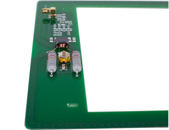
What Is an Embedded PCB Antenna?
An embedded PCB antenna is an antenna structure created using copper traces on the PCB. Instead of installing a discrete antenna module, engineers design a specific copper pattern that radiates RF signals.
These antennas operate using electromagnetic radiation generated by alternating current flowing through the copper trace.
Typical characteristics include:
Copper trace acting as the radiating element
Integration into PCB layers or surface traces
Connection to RF transceivers via a 50-ohm impedance line
Use of tuning components for impedance matching
Embedded antennas are commonly used in frequencies such as:
Among these, the 2.4 GHz embedded PCB antenna is the most widely used due to the popularity of WiFi and Bluetooth devices.
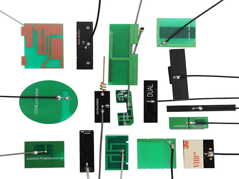
Types of Embedded PCB Antennas
Different antenna structures are used depending on frequency, PCB size, and product design constraints.
Inverted-F Antenna (IFA)
The inverted-F antenna is one of the most common pcb embedded antenna designs.
Key characteristics include:
Compact layout
Good impedance matching
Suitable for 2.4 GHz communication
This antenna structure is widely used in:
WiFi modules
Bluetooth devices
IoT communication modules
Meandered PCB Antenna
A meandered antenna uses a serpentine copper trace that increases electrical length without increasing physical size.
Advantages include:
Compact footprint
Efficient low-frequency operation
Suitable for small devices
It is commonly used in:
IoT sensors
LoRa devices
wireless control modules
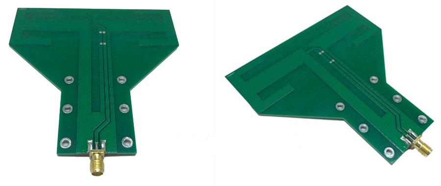
Loop Antenna
A loop antenna consists of a closed copper loop that radiates electromagnetic energy.
Typical uses include:
RFID systems
wireless communication devices
NFC systems
In many smartphones and access control systems, an embedded pcb nfc antenna is implemented as a loop antenna around the PCB.
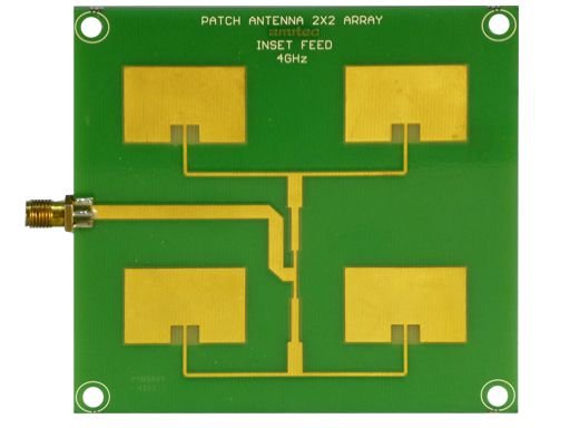
Patch Antenna
Patch antennas are flat metal patches placed above a ground plane.
They provide:
directional radiation
higher gain
stable performance
Applications include:
GPS receivers
satellite communication systems
automotive radar
How Embedded PCB Antennas Work?
Embedded antennas convert electrical signals into electromagnetic waves. When RF current flows through the antenna trace, it generates an oscillating electromagnetic field that radiates into space.
The efficiency of radiation depends on several design factors.
Antenna Length
A key rule in antenna design is the quarter-wavelength principle.
The approximate antenna length is:
Frequency
Quarter Wavelength
433 MHz
~17 cm
915 MHz
~8 cm
2.4 GHz
~3.1 cm
Because space is limited on PCBs, engineers often use meander structures to compress antenna length.
Impedance Matching
Most RF systems use 50-ohm impedance. If the antenna impedance does not match the RF circuit, signal reflections occur.
Matching networks are commonly used.
Typical structures include:
Pi matching network
T matching network
LC matching circuits
These components help optimize antenna efficiency and radiation performance.
Ground Plane Influence
The ground plane strongly affects antenna performance.
Key considerations include:
sufficient ground clearance around the antenna
avoiding large metal components nearby
controlling return current paths
Improper ground design can significantly reduce antenna efficiency.
Embedded PCB Antennas vs External Antennas
Engineers often choose between embedded antennas and external antennas depending on product requirements.
Feature
Embedded PCB Antenna
External Antenna
Size
Very compact
Larger
Cost
Lower
Higher
RF performance
Moderate
Usually stronger
Integration
High
Low
Mechanical reliability
High
Connector dependent
External antennas are often preferred when:
maximum transmission distance is required
RF performance is critical
PCB size is extremely small
Embedded antennas are preferred when:
product size is limited
cost must be minimized
industrial design requires hidden antennas
Design Factors That Affect Embedded PCB Antenna Performance
Designing a reliable embedded antenna PCB requires careful consideration of multiple parameters.
PCB Material
The dielectric constant of the PCB affects signal propagation.
Common materials include:
Material
Typical Use
FR4
Standard IoT devices
Rogers
High-frequency applications
PTFE
Advanced RF designs
For most consumer devices, FR4 is sufficient for 2.4 GHz embedded PCB antenna designs.
PCB Stackup
Stackup influences antenna impedance and radiation pattern.
Key parameters include:
dielectric thickness
copper thickness
ground plane position
Proper stackup planning is critical for RF performance.
Component Placement
Components near the antenna can interfere with signal radiation.
Engineers typically avoid placing these near antennas:
batteries
shielding cans
large metal connectors
Maintaining a dedicated antenna clearance area is essential.
Antenna Tuning
Even well-designed antennas often require tuning during prototyping.
Common RF testing tools include:
Vector Network Analyzer (VNA)
RF simulation software
spectrum analyzers
These tools help optimize antenna performance before mass production.
Applications of Embedded PCB Antennas
Embedded antennas are widely used across many industries.
Industry
Application
IoT
smart sensors
Smart home
WiFi devices
Medical
wireless monitoring
Automotive
telematics
Industrial
wireless automation
Consumer electronics
wearable devices
For example, smart home devices often use 2.4 GHz embedded PCB antennas to support WiFi or Bluetooth connectivity.
Similarly, access control systems rely on embedded PCB NFC antennas for contactless communication.
Why Choose EBest Circuit for Embedded PCB Antennas?
Designing and manufacturing embedded antennas requires expertise in both RF engineering and PCB fabrication.
EBest Circuit (Best Technology) provides complete support for antenna PCB development, including design consultation, prototyping, and mass production.
Key advantages include:
Professional engineering support team for full-process technical assistance
Free DFM review and BOM optimization by experienced engineers
Certifications including ISO9001, ISO13485, IATF16949, and AS9100D
Digital manufacturing system with full traceability
With more than 20 years of PCB and PCBA manufacturing experience, EBest Circuit helps customers successfully develop high-performance wireless products.
In summary, embedded PCB antennas have become an essential technology in modern wireless electronics. By integrating antenna structures directly into the PCB, designers can reduce product size, lower manufacturing cost, and improve reliability.
From 2.4 GHz embedded PCB antennas used in WiFi devices to embedded PCB NFC antennas used in contactless systems, this antenna technology enables compact and efficient wireless products across many industries.
As wireless devices continue to expand across IoT, medical, automotive, and industrial markets, embedded antenna design will remain a critical element of PCB engineering.
An embedded PCB antenna is a wireless antenna created directly from copper traces on a printed circuit board instead of using an external antenna component.
What frequency is commonly used for embedded PCB antennas?
The most common frequency is 2.4 GHz, which supports WiFi and Bluetooth communication.
Can FR4 be used for embedded antennas?
Yes. FR4 is widely used for most consumer electronics and works well for 2.4 GHz embedded PCB antenna designs.
What is an embedded PCB NFC antenna?
An embedded PCB NFC antenna is typically a loop antenna designed on the PCB to enable near-field communication at 13.56 MHz.
How do engineers tune PCB antennas?
Engineers use RF test equipment such as vector network analyzers to measure antenna impedance and adjust matching components.
This website uses cookies to enhance your experience, remember your preferences, and help us understand how visitors use our site. You can accept all cookies, reject non-essential cookies, or manage your settings.
This website uses cookies to improve your experience while you navigate through the website. Out of these cookies, the cookies that are categorized as necessary are stored on your browser as they are essential for the working of basic functionalities of the website. We also use third-party cookies that help us analyze and understand how you use this website. These cookies will be stored in your browser only with your consent. You also have the option to opt-out of these cookies. But opting out of some of these cookies may have an effect on your browsing experience.
Necessary cookies are absolutely essential for the website to function properly. These cookies ensure basic functionalities and security features of the website, anonymously.
Cookie
Duration
Description
cookielawinfo-checkbox-analytics
11 months
This cookie is set by GDPR Cookie Consent plugin. The cookie is used to store the user consent for the cookies in the category "Analytics".
cookielawinfo-checkbox-functional
11 months
The cookie is set by GDPR cookie consent to record the user consent for the cookies in the category "Functional".
cookielawinfo-checkbox-necessary
11 months
This cookie is set by GDPR Cookie Consent plugin. The cookies is used to store the user consent for the cookies in the category "Necessary".
cookielawinfo-checkbox-others
11 months
This cookie is set by GDPR Cookie Consent plugin. The cookie is used to store the user consent for the cookies in the category "Other.
cookielawinfo-checkbox-performance
11 months
This cookie is set by GDPR Cookie Consent plugin. The cookie is used to store the user consent for the cookies in the category "Performance".
viewed_cookie_policy
11 months
The cookie is set by the GDPR Cookie Consent plugin and is used to store whether or not user has consented to the use of cookies. It does not store any personal data.
Functional cookies help to perform certain functionalities like sharing the content of the website on social media platforms, collect feedbacks, and other third-party features.
Performance cookies are used to understand and analyze the key performance indexes of the website which helps in delivering a better user experience for the visitors.
Analytical cookies are used to understand how visitors interact with the website. These cookies help provide information on metrics the number of visitors, bounce rate, traffic source, etc.
Advertisement cookies are used to provide visitors with relevant ads and marketing campaigns. These cookies track visitors across websites and collect information to provide customized ads.