Looking for high-performance, reliable automotive MCPCB design that excels in heat dissipation, extreme environments, and long-term durability? This guide covers everything you need to know about automotive-grade MCPCB design, thermal best practices, reliability solutions, and how to get the most stable and high-quality products for your automotive electronic applications.
EBest provides high-performance automotive MCPCB design with excellent thermal conductivity, full automotive certifications, and extreme environment adaptability for reliable vehicle electronics.
Why Choose EBest for Your Automotive MCPCB Design Needs?
We deliver fully customized automotive MCPCB design solutions tailored to the strict requirements of the automotive industry, focusing on thermal efficiency, structural stability, and long‑term performance for critical vehicle electronics. Every design is optimized to eliminate overheating risks, improve component lifespan, and ensure stable operation under harsh conditions.
We provide end‑to‑end engineering support throughout the entire design and validation process, including professional thermal simulation, DFM analysis, reliability testing, and structural optimization. Our technical team works closely with you to resolve design challenges, reduce development cycles, and ensure your project meets all automotive quality standards.
We maintain a stable, automotive‑grade supply chain and robust quality control system, ensuring consistent material quality, strict production standards, and reliable delivery for both prototype development and large‑scale applications. Our solutions are built to reduce failure risks and enhance the overall performance of your automotive electronic systems.
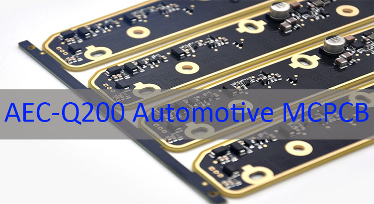
Our Certifications & Quality System for Automotive MCPCB Design
- IATF 16949: Full process control for automotive manufacturing, eliminating quality risks
- ISO 9001:2015: Universal quality management system ensuring consistent product quality
- ISO 13485:2016: High‑reliability control suitable for critical electronic components
- AS9100D: Stringent aerospace‑grade quality standards for maximum stability
- REACH & RoHS: Environmental compliance meeting global regulatory standards
- UL: Safety certification for high‑stability electronic applications
These certifications ensure every automotive MCPCB design from EBest meets strict automotive safety, reliability, and compliance standards.
What Are the Pain Points in Automotive MCPCB Design?
Pain Point 1: Poor heat dissipation leading to component overheating
Our Solution: Optimized thermal stack‑up, high‑conductivity substrates, and professional thermal via design for efficient heat transfer.
Pain Point 2: Insufficient reliability under thermal cycling and vibration
Our Solution: Automotive‑grade materials, reinforced structural design, and strict reliability testing to resist extreme conditions.
Pain Point 3: Design for Manufacturing (DfM) issues causing low production yield
Our Solution: Pre‑production DfM review, standardized design guidelines, and production‑friendly layout optimization.
Pain Point 4: Inconsistent material quality affecting long‑term performance
Our Solution: Certified automotive‑grade raw materials and full batch traceability for consistent quality.
Pain Point 5: Long lead times delaying project development
Our Solution: Rapid design validation, streamlined production lines, and fast prototype services.
Pain Point 6: Non‑compliance with automotive industry standards
Our Solution: Full adherence to IATF 16949 and global automotive regulations with complete certification support.
How Does Thermal Management Impact Automotive MCPCB Performance?
Effective thermal management is the foundation of stable and long‑lasting automotive MCPCB design in vehicle electronics. Without proper heat control, power components such as LEDs, drivers, and control modules will overheat, leading to performance degradation, shortened lifespan, and even sudden failures.
High thermal conductivity in MCPCB designs quickly transfers heat away from heat‑generating components, maintaining safe operating temperatures even under continuous high loads. This directly improves the stability, efficiency, and durability of automotive electronic systems.
Our automotive MCPCB design integrates advanced thermal management strategies, including optimized dielectric layers, heavy copper layouts, and strategic thermal vias, to maximize heat dissipation and ensure reliable performance in real‑world driving conditions.
What Materials Are Best for Automotive MCPCB Design?
| Material Type | Key Benefits | Ideal Applications |
|---|---|---|
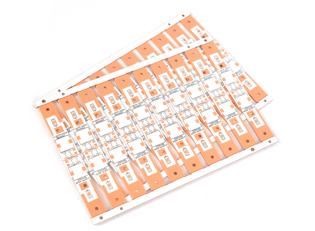
| Aluminum Core Substrate | Lightweight, cost‑effective, good thermal conductivity | General automotive lighting, control modules |
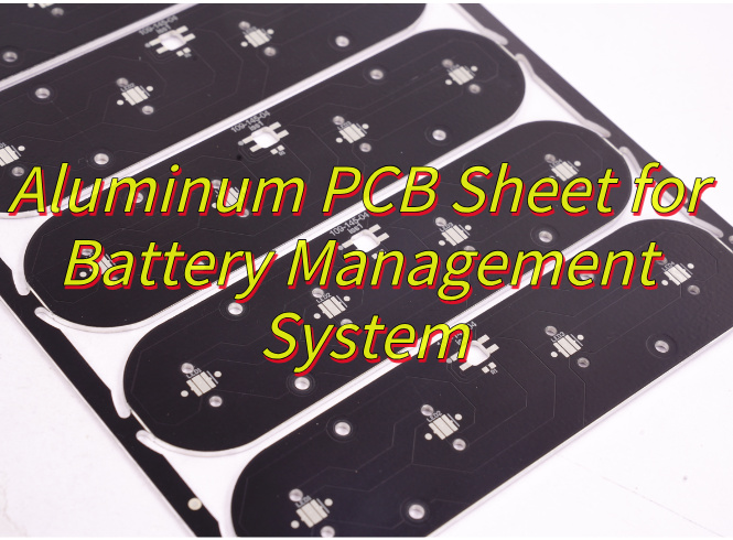
| Copper Core Substrate | Ultra‑high thermal conductivity, excellent heat dissipation | High‑power EV components, inverters, BMS |
| High‑Performance Dielectric | Strong electrical isolation, enhanced thermal transfer | Critical safety systems, high‑temperature environments |
| Heavy Copper Foil | High current carrying capacity, improved heat spread | Power distribution, motor control units |
How to Ensure Reliability in Automotive MCPCB Design?
Reliability is non‑negotiable in Automotive MCPCB design due to the harsh conditions of vehicle operation, including extreme temperatures, vibration, humidity, and thermal shock. Poor reliability can lead to system failures and safety risks.
Our design process includes comprehensive thermal cycling testing, vibration simulation, humidity resistance testing, and service life evaluation to validate performance before mass production. We only use qualified automotive‑grade materials to ensure stability.
EBest’s integrated design and quality system ensures every automotive MCPCB maintains consistent performance over long lifecycles, even in the most demanding under‑hood and on‑board environments.
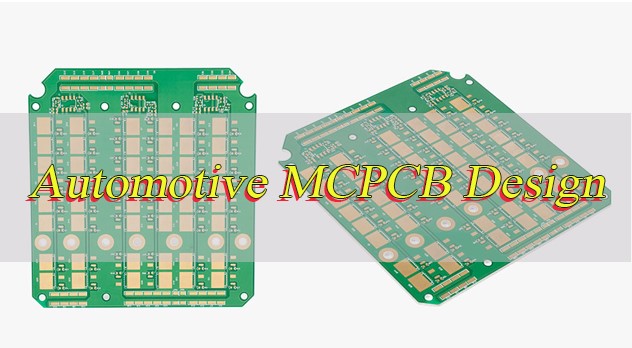
What Is DFM in Automotive MCPCB Design and Why Does It Matter?
Design for Manufacturing (DfM) is a critical process in Automotive MCPCB design that optimizes layouts, structures, and dimensions for stable, high‑yield production. It bridges design theory and real‑world manufacturing capabilities.
Without effective DFM analysis, designs may face issues such as difficult assembly, low production yield, structural defects, and increased failure rates. This leads to delays, rework, and higher long‑term costs.
Our engineering team provides professional DfM reviews at the early design stage, optimizing trace widths, clearances, component placement, and thermal structures. This ensures smooth production, consistent quality, and high reliability for every project.
How to Optimize Thermal Conductivity in Automotive MCPCB Design?
Thermal conductivity optimization is central to high‑performance automotive MCPCB design. The goal is to create a fast, efficient heat path from power components to the heat sink and surrounding environment.
Key methods include selecting high‑thermal‑conductivity metal core substrates, using thin, high‑performance dielectric layers, adding thermal vias, and increasing copper thickness for better heat spreading. Each parameter is customized based on power load and environment.
Our engineering team uses professional thermal simulation tools to design the best thermal solution for your specific application, ensuring maximum heat dissipation and stable operating temperatures.
What Are Real‑World Applications of Automotive MCPCB Design?
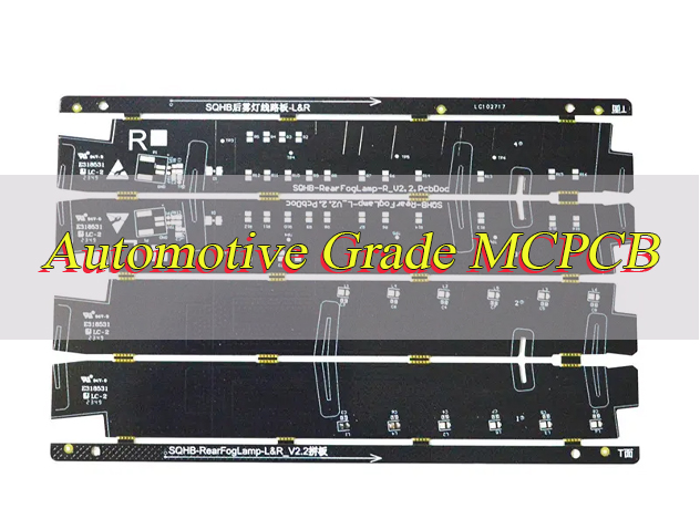
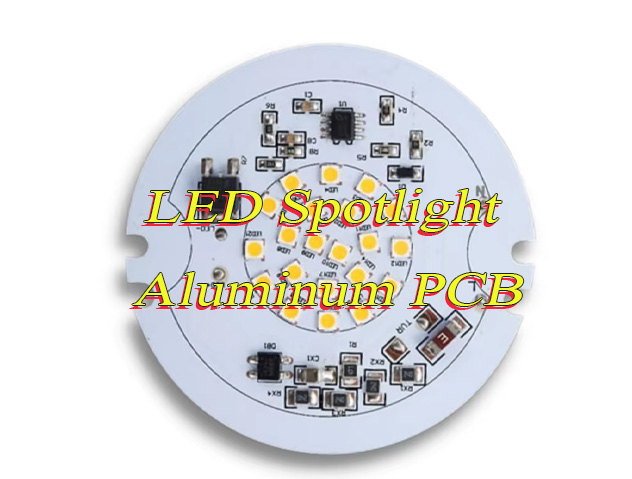
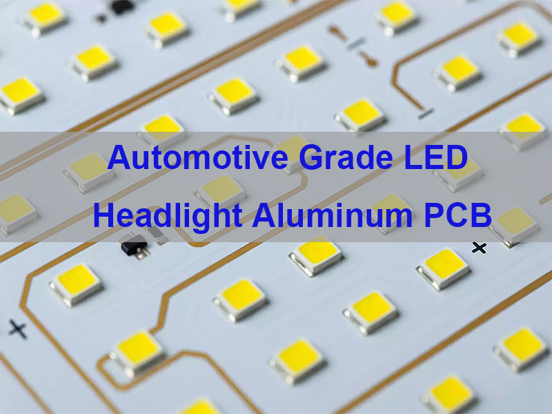
Automotive MCPCB design is widely used in core automotive electronic systems, including LED headlights and taillights, electric vehicle powertrain modules, battery management systems (BMS), engine control units, and ADAS sensors.
In a real‑world case, our customized automotive MCPCB design solved severe overheating problems in automotive LED headlights. The original design suffered from heat buildup and rapid lumen depreciation.
After implementing our thermal‑optimized MCPCB solution, the operating temperature dropped significantly, service life improved by 200%, and the product passed rigorous thermal cycling and vibration tests required by automotive manufacturers.
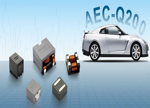
How Does Extreme Environment Affect Automotive MCPCB Design?
Automotive electronics operate in extremely harsh environments, including high and low temperatures, rapid temperature changes, strong vibration, humidity, and chemical exposure. These conditions directly determine the requirements for automotive MCPCB design.
Standard electronic components cannot withstand these stresses, leading to cracking, delamination, performance loss, or sudden failure. Automotive MCPCBs must be specially designed to resist these challenges.
EBest’s automotive MCPCB design uses rugged materials, reinforced structures, and stress‑relief layouts to maintain performance and structural integrity in extreme environments, ensuring long‑term reliability.
Frequently Asked Questions About Automotive MCPCB Design
Q1: What thermal conductivity range is ideal for automotive MCPCB?
A1: Thermal conductivity from 2.0 W/m·K to 10.0 W/m·K is commonly used for automotive applications, based on power requirements, heat load, and operating environment.
Q2: How long does automotive MCPCB prototype take?
A2: Rapid prototypes can be completed and shipped within 24–48 hours to support urgent development schedules and project validation.
Q3: Are EBest automotive MCPCBs compatible with lead‑free assembly?
A3: Yes, all our designs fully support lead‑free SMT assembly and reflow processes, meeting global automotive production requirements.
Q4: Can you handle heavy copper in automotive MCPCB design?
A4: Yes, we support heavy copper designs for high‑current automotive power applications, including EV systems and power distribution modules.
Q5: Do you provide design support for automotive MCPCB projects?
A5: Our expert engineering team offers full design, simulation, DFM support, and reliability testing for every automotive MCPCB project.
Q6: What industries use your automotive MCPCB solutions?
A6: Our products serve automotive lighting, EV powertrain, BMS, infotainment, ADAS systems, and other critical vehicle electronic applications.
Get Your Automotive MCPCB Design from EBest Today
EBest delivers professional Automotive MCPCB design with rapid prototyping, dedicated engineering support, and automotive‑grade quality you can trust.
We prioritize urgent orders and offer exclusive support for both prototype and mass production projects, ensuring fast turnaround and consistent high quality.
Contact us now to discuss your project: sales@bestpcbs.com — EBest is your reliable automotive MCPCB partner.