How to solve overheating, component failure and reliability issues in automotive battery management systems and ensure efficient BMS operation in harsh vehicle environments? High-quality automotive BMS MCPCB provides the solution. It delivers the thermal conductivity, structural stability and electrical isolation critical to BMS performance. This blog covers key design considerations, real-world applications, common challenges and solutions for automotive BMS MCPCB. It also explains why EBest is the top choice for your automotive BMS MCPCB needs, whether you need thermal management optimization, long-term reliability or a trusted supplier.
Why Choose EBest for Your Automotive BMS MCPCB Manufacturer?
EBest delivers automotive-grade automotive BMS MCPCB solutions tailored to your needs. We combine proven expertise, strict quality control and reliable support to ensure your BMS projects run smoothly, with no delays or compromises on performance.
- Superior Quality & Compliance: Our automotive BMS MCPCB meets IATF 16949 and other automotive standards, with full material traceability and rigorous testing to ensure consistency and reliability.
- Optimized Thermal Performance: Built with high-quality materials to deliver 1–10 W/m·K thermal conductivity, our boards effectively dissipate BMS heat, preventing component failure and extending service life.
- Flexible Customization: We offer tailored designs for automotive BMS MCPCB, adjusting thickness, copper weight and surface finishes to match your specific BMS application needs.
- Reliable Lead Times: Fast prototyping (7–10 days) and stable mass production scheduling keep your projects on track, avoiding costly delays.
- Expert Support: Our team provides dedicated engineering assistance for DFM and thermal optimization, ensuring your BMS design is efficient and manufacturable.
- Stable Supply Chain: Verified material sources and consistent production capacity guarantee steady supply, even for large-scale orders.
EBest’s Certifications for Automotive BMS MCPCB: Proof of Quality and Compliance
Our commitment to quality is backed by industry-leading certifications, ensuring our automotive BMS MCPCB meets global automotive standards:
- IATF 16949: Automotive-specific quality standard, ensuring our automotive BMS MCPCB meets OEM requirements and adheres to strict automotive industry quality control processes.
- ISO 9001:2015: The international standard for quality management systems, providing a framework to ensure consistent, high-quality production of our automotive BMS MCPCB and continual improvement of our processes.
- ISO 13485:2016: Medical device quality management system standard, ensuring our automotive BMS MCPCB meets the high-reliability requirements for medical-related automotive applications.
- AS9100D: Aerospace quality management system standard, guaranteeing our automotive BMS MCPCB meets the rigorous reliability and performance standards required for aerospace and high-end automotive applications.
- REACH: EU chemical compliance standard, ensuring our automotive BMS MCPCB is free from restricted chemicals and safe for global markets.
- RoHS: Compliance with restrictions on hazardous substances, meeting global environmental standards and ensuring our automotive BMS MCPCB is eco-friendly.
- UL: Safety and flammability compliance standard, critical for automotive electrical systems and ensuring our automotive BMS MCPCB meets strict safety requirements.
Common Pain Points of Automotive BMS MCPCB: How EBest Solves Your BMS Challenges
Automotive BMS performance issues often stem from inadequate thermal management, poor durability and subpar component reliability. These challenges can lead to costly delays, reduced battery life and safety risks. Below are the most common pain points teams face with automotive BMS MCPCB, along with practical solutions from EBest to resolve them.
- Excess Heat Buildup: MOSFETs, shunts and ICs in BMS generate significant heat during operation. This heat reduces efficiency and leads to premature component failure, a critical issue since 38% of battery failures in electric vehicles trace back to BMS malfunctions. Our automotive BMS MCPCB offers 3–5x better thermal conductivity than standard PCBs, rapidly dissipating heat to keep components cool and prevent performance drops.
- Weak Thermal Dissipation with FR4: Traditional FR4 PCBs have low thermal conductivity (0.3–0.5 W/m·K), making them unable to handle high currents and heat in modern BMS designs. This increases the risk of thermal runaway, especially when temperatures exceed 60°C. Our automotive BMS MCPCB uses thermally enhanced metal cores to replace FR4, preventing thermal runaway and extending BMS service life.
- Temperature Imbalance: Uneven heat distribution across BMS modules shortens battery cycle life and raises failure risks. Even small temperature inconsistencies can reduce battery lifespan by 20–30% over time. Our automotive BMS MCPCB ensures uniform heat dissipation, balancing temperatures across the entire module to protect battery health.
- Mechanical Instability: Vibration and humidity in vehicle environments weaken standard PCBs, leading to structural damage and connection failures. Commercial vehicles face a 30% failure rate due to poor vibration resistance. Our automotive BMS MCPCB uses durable aluminum cores to withstand harsh automotive conditions, ensuring long-term mechanical stability and reliability.
- Inconsistent Quality & Traceability: Many low-quality MCPCBs lack material traceability and fail to meet automotive standards, leading to batch inconsistencies and compliance issues. EBest’s automotive BMS MCPCB comes with full material traceability and rigorous testing, ensuring consistent quality and adherence to global automotive standards.
EBest’s automotive BMS MCPCB is engineered to address these core pain points comprehensively. Our solutions combine thermal efficiency, mechanical durability and strict quality control to ensure your BMS operates reliably. Choose EBest for automotive BMS MCPCB that solves your challenges and keeps your projects on track.
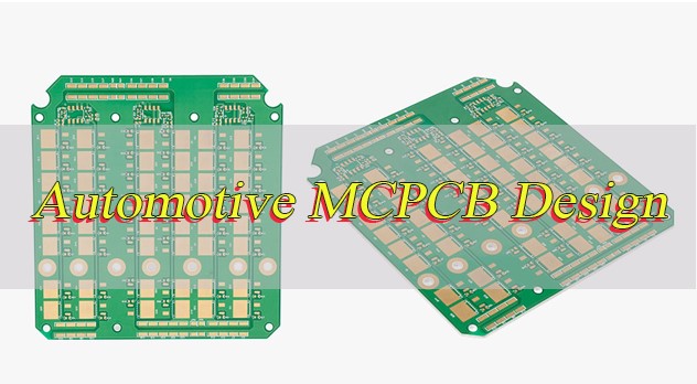
What Is an Automotive BMS MCPCB?
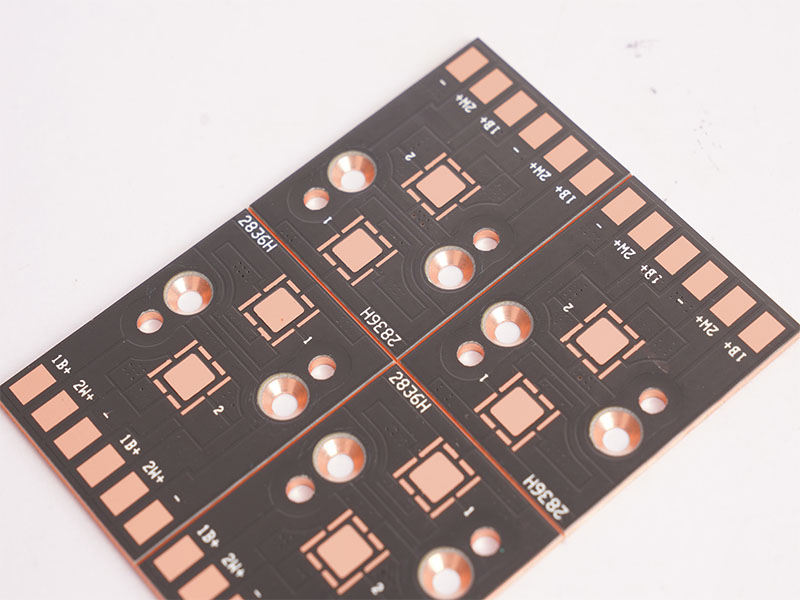
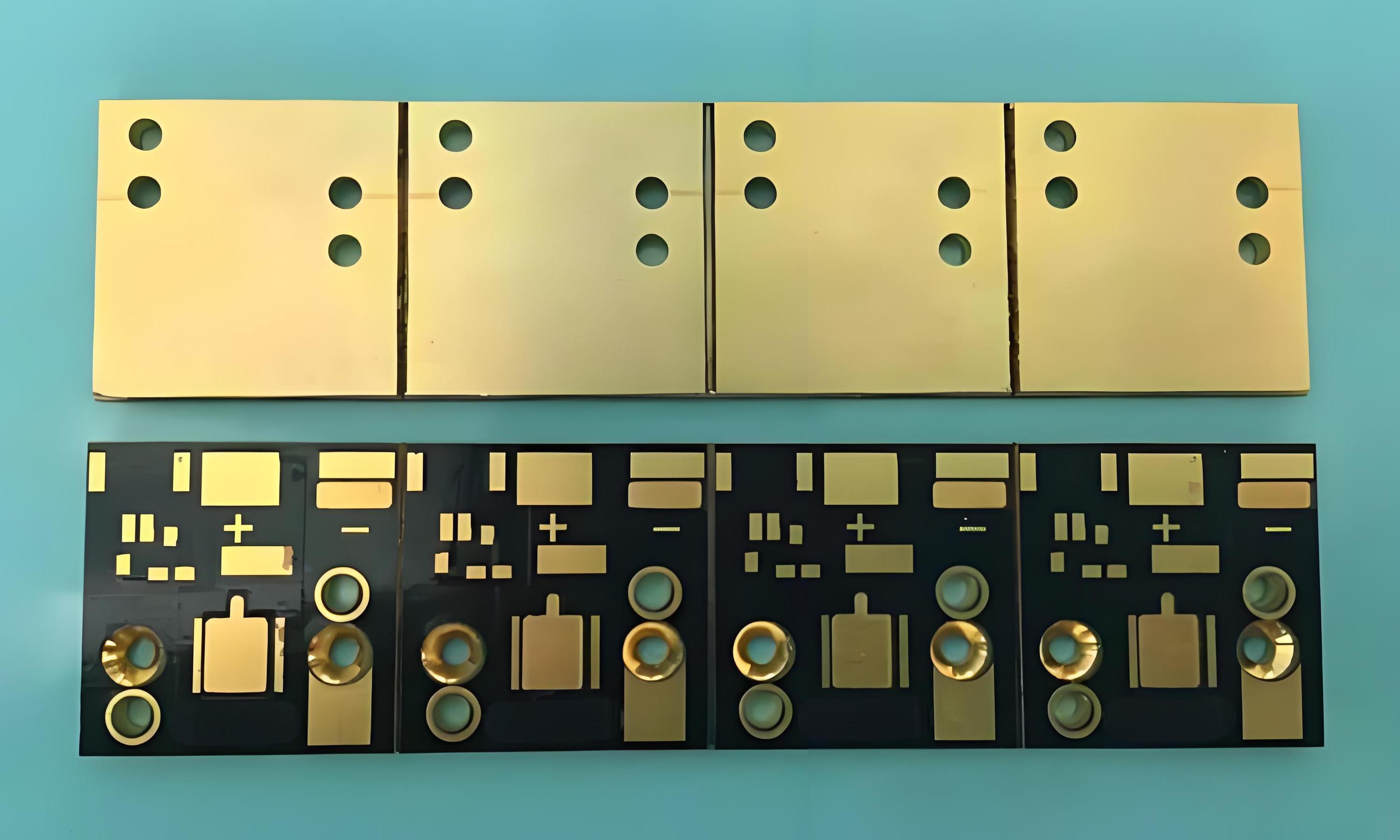
An automotive BMS MCPCB (Metal Core Printed Circuit Board) is a specialized, thermally enhanced circuit board made specifically for vehicle battery management systems. It differs from standard PCBs by using a metal base, usually aluminum, to address the unique heat challenges of BMS applications.
A thin dielectric layer sits between the metal base and the circuit layer. This layer keeps the circuit electrically isolated while letting heat transfer efficiently from the board to the metal core. This design is critical for BMS performance. It pulls heat away from high-power components like MOSFETs and shunts, preventing overheating that can damage parts or reduce battery life.
Automotive BMS MCPCB is built to handle the high currents and extreme temperature swings of vehicle environments. It ensures reliable BMS operation, which is essential for electric and hybrid vehicle performance and safety.
Why Use MCPCB Instead of FR4 for BMS?
| Metric | Automotive BMS MCPCB | FR4 PCB |
| Thermal Conductivity (Critical for BMS Heat Dissipation) | 1–10 W/m·K, efficiently dissipates heat from MOSFETs, shunts and ICs to prevent overheating. | 0.3–0.5 W/m·K, too low to handle high-power BMS heat, leading to component overheating. |
| BMS Component Reliability | Prevents thermal runaway and premature component failure, extending BMS service life significantly. | High risk of component damage due to poor heat dissipation, shortening BMS lifespan. |
| Ability to Handle High Currents | Designed for high-current BMS charging/discharging paths, supports 48V, 400V and 800V BMS designs. | Struggles with modern high-current BMS applications, prone to performance drops or failure. |
| Mechanical Stability (Automotive Environment) | Rigid metal core (aluminum) resists vibration, humidity and thermal cycling in vehicle environments. | Fiberglass base is fragile, prone to warpage and solder joint failure under automotive vibration. |
| Battery Life Impact | Balances module temperatures, prevents thermal degradation and extends battery cycle life by 20–30%. | Temperature imbalance shortens battery life, increasing long-term replacement costs. |
| Automotive Compliance | Meets IATF 16949 and other automotive standards, suitable for OEM BMS applications. | Not optimized for automotive standards, may fail compliance checks for vehicle use. |
| Design Flexibility | Customizable thickness, copper weight and surface finishes to match specific BMS design needs. | Limited customization, not adaptable to high-performance BMS requirements. |
How Does Thermal Conductivity Affect BMS Performance?
Thermal conductivity is the most critical parameter for automotive BMS MCPCB, directly impacting how well your BMS operates. It measures how quickly heat moves through the board, and higher conductivity means better heat dissipation. For automotive BMS, thermal conductivity requirements vary by application:
- 1–2 W/m·K: Ideal for low-power BMS sections, such as monitoring circuits.
- 3–4 W/m·K: Perfect for mid-power BMS modules, balancing performance and cost.
- 5–10 W/m·K: Essential for high-current charging and discharge paths, where heat generation is highest.
Higher thermal conductivity in automotive BMS MCPCB means lower component temperatures, better BMS stability, and longer battery life.
What Materials Are Used in Automotive BMS MCPCB?
EBest uses controlled, traceable materials for automotive BMS MCPCB:
- Base Material: EBest uses Aluminum 5052 or 6061 for the core of automotive BMS MCPCB. These aluminum alloys provide excellent thermal conductivity and strong mechanical strength, making them suitable for automotive environments with vibration, humidity and extreme temperature changes.
- Dielectric Layer: The dielectric layer is made of thermally conductive ceramic filled polymer. It maintains electrical isolation between the circuit and metal base while enabling efficient heat transfer from the circuit layer to the metal core for quick dissipation. This material can achieve high dielectric constants by filling ceramic powders like BaTiO3, enhancing overall performance.
- Circuit Layer: The circuit layer adopts 1–6 oz rolled annealed copper to ensure reliable current handling for all BMS circuit needs. Thicker copper options are available for high current BMS applications to maintain stable performance and avoid overheating.
- Surface Finish: EBest offers three high performance surface finishes HASL, ENIG and Immersion Silver. All options provide superior solderability and corrosion resistance to ensure strong and durable component connections for automotive BMS. HASL is ideal for high power components while Immersion Silver fits high reliability scenarios.
All materials used in EBest automotive BMS MCPCB are high quality and fully traceable. They are carefully selected to meet the harsh demands of automotive environments and ensure consistent performance and long term reliability for your BMS projects.
What Are the Key Design Rules for Automotive BMS MCPCB?
Designing an automotive BMS MCPCB requires careful attention to thermal management and component placement. Follow these key rules to ensure your BMS design is efficient and reliable:
- Maximize copper area under power components like MOSFETs and shunts to improve heat dissipation. Larger copper areas increase heat transfer efficiency, reducing component temperatures by 15–25% and lowering the risk of thermal fatigue, which is critical for high-power BMS operation.
- Place hot components away from sensitive ICs to prevent thermal interference and damage. Sensitive BMS ICs (such as voltage monitoring chips) have strict operating temperature limits (typically 0–85°C), and placing them near hot components can cause measurement errors or premature failure.
- Use thermal vias and thermal pads to transfer heat from the circuit layer to the metal core of the automotive BMS MCPCB. Thermal vias (arranged in a grid pattern) enhance heat transfer by 30–40% compared to standard vias, ensuring heat is quickly dissipated to the aluminum core and away from critical components.
- Maintain proper dielectric isolation for high-voltage BMS applications, following automotive safety standards. For 400V+ BMS designs, the dielectric layer thickness should be at least 100μm to prevent electrical breakdown, while 800V systems require thicker dielectric layers to meet isolation requirements.
- Adhere to creepage and clearance requirements to prevent electrical arcing and ensure BMS safety. For 800V BMS systems, follow GB/T 18384.3 standards: high-voltage line spacing should be ≥8mm, and line-to-ground spacing ≥6mm; add 10% redundancy to offset production etching deviations (line width tolerance ±0.03mm).
- Match copper weight to BMS current requirements to avoid voltage drop and overheating. For low-current monitoring circuits, 1–2 oz copper is sufficient; high-current charging/discharging paths require 4–6 oz copper to handle currents up to 100A without performance loss.
- Use rounded corners for high-voltage traces and copper pads instead of right angles. Right-angle traces create electric field concentration, increasing the risk of arcing in harsh automotive environments; rounded corners (radius ≥1mm) reduce this risk and improve overall board reliability.
- Separate analog and digital circuits on the MCPCB to minimize electromagnetic interference (EMI). BMS voltage monitoring (analog) and control signals (digital) are susceptible to EMI, which can cause data inaccuracies; separating these circuits with a ground plane reduces interference and ensures stable BMS operation.
- Incorporate a solid ground plane connected to the MCPCB’s metal core to enhance EMI shielding and heat dissipation. The ground plane acts as a shield against external interference and provides an additional heat dissipation path, further protecting sensitive BMS components.
- Avoid unnecessary cutouts in the MCPCB metal core. Cutouts disrupt heat distribution and reduce mechanical stability, making the board more prone to warpage under automotive thermal cycling; only use cutouts when required for component fit or assembly.
How to Ensure Reliability in Automotive BMS MCPCB?
Reliability is critical for automotive BMS as failures cause battery damage safety risks and downtime. A 2026 study shows 45% of automotive electronic failures stem from thermal cycling and 30% from vibration requiring strict quality control. Below are practical steps to ensure automotive BMS MCPCB reliability:
- Demand Full Material Traceability and Compliance Certificates: Request COC for all MCPCB materials to meet automotive grade standards. EBest provides full traceability and documentation to meet IATF 16949 and OEM requirements avoiding subpar performance.
- Implement Strict Thermal Cycling and Thermal Shock Testing: Automotive BMS MCPCB must withstand -40℃ to 125℃. Follow AEC Q100 Rev H conduct 1500 cycles of -40℃ 30min to 125℃ 30min to simulate 10 years of use and verify resistance to delamination and solder joint cracking.
- Conduct Comprehensive Electrical Integrity Testing: Perform open short circuit and Hi Pot tests. For 400V plus BMS use 1500V DC for 60 seconds to verify dielectric integrity and prevent arcing or short circuits.
- Verify Solderability and Component Adhesion: Test solder joint strength to meet IPC 6012 Class 3. EBest uses vacuum reflow soldering oxygen content less than 100ppm to keep solder void rate below 5% for strong component bonds.
- Test for Vibration and Humidity Resistance: Follow ISO 16750 3 conduct 32 hours of random vibration and 50g impact tests. Perform 10 cycles of salt fog damp heat and drying to prevent corrosion.
- Inspect for Manufacturing Defects with X Ray and Visual Testing: Use X Ray to detect hidden defects and visual inspection per IPC A 600 to check for damage reducing defect rates by up to 70%.
- Validate Long Term Durability with Accelerated Aging Tests: Conduct 1000 hours of 85℃/85% RH damp heat testing. EBest’s MCPCB maintains less than 10% electrical performance change ensuring long term reliability.
EBest automotive BMS MCPCB undergoes all these quality control steps ensuring high reliability for harsh automotive environments.
Real Automotive BMS MCPCB Application Examples
Real Automotive BMS MCPCB Application Examples: Solving Real-World BMS Problems
- 48V Mild Hybrid BMS
- Board: 3.0 W/m·K automotive BMS MCPCB
- Function: MOSFET and current shunt monitoring for hybrid vehicle BMS.
- Solution: Reduces MOSFET temperature by 28°C, improving BMS efficiency and preventing overheating. This ensures the hybrid system operates smoothly, reducing fuel consumption and emissions.
- EV Main Battery Control Module
- Board: 5.0 W/m·K high-thermal automotive BMS MCPCB
- Function: Charge and discharge power regulation for electric vehicle main batteries.
- Solution: Balances cell temperature across the battery pack, extending battery cycle life and improving charging efficiency. This helps EVs achieve longer range and more reliable performance.
- BMS Protection & Balancing Board
- Board: 2.0 W/m·K automotive BMS MCPCB
- Function: Passive cell balancing for automotive BMS, ensuring even charge distribution.
- Solution: Lowers balancing resistor heat and prevents hotspots, reducing the risk of component failure and extending BMS life.
How to Optimize DFM for Automotive BMS MCPCB?
Design for manufacturability (DFM) is key to reducing costs, improving yield and speeding up production of automotive BMS MCPCB. Follow these practical, easy-to-follow tips to optimize your DFM:
- Simplify the layer structure (preferably 1–2 layers for standard BMS modules) and avoid unnecessary cutouts. This reduces production complexity, material waste and errors, while aligning with IPC-6012 Class 3 guidelines.
- Standardize thermal pad sizes to 5mm×5mm or 10mm×10mm to match common BMS component footprints. Non-standard sizes increase solder voids and costs, while standardization improves yield and compatibility with automated assembly.
- Minimize small, dense features. Follow IPC-2221 standards (minimum 0.15mm trace width for automotive BMS) to reduce etching errors and avoid costly specialized production processes.
- Use surface finishes compatible with your BMS components. EBest recommends HASL for high-power components (MOSFETs, shunts) and ENIG for sensitive ICs to prevent solder joint cracking and ensure reliability.
- Align designs with standard production capabilities. Use 1.0mm (low-power BMS) or 1.6mm (high-power BMS) base thicknesses to avoid lead time delays and cost overruns from custom sizes.
- Optimize copper weight to match BMS current needs. Follow the 1oz copper per 30A rule to avoid over-engineering, reduce material costs and speed up etching processes.
- Design uniform solder mask openings, standardizing to 0.1mm larger than the pad size. This ensures consistent solder application and aligns with automated stencil printing.
- Avoid tight tolerances unless critical. A ±0.03mm tolerance is sufficient for most automotive BMS applications, reducing costs from specialized equipment and maintaining performance.
- Place test points along board edges (at least 2mm from edges) for easy access. This simplifies quality inspection, improves efficiency and reduces the risk of missed defects.
- Collaborate with your MCPCB supplier early in the design phase. Early collaboration reduces DFM-related redesigns by 60% and shortens lead times, with EBest offering free DFM reviews to identify issues upfront.
What Testing Standards Apply to Automotive BMS MCPCB?
Automotive BMS MCPCB must meet strict testing standards to ensure reliability and safety. The most important standards for automotive BMS MCPCB include:
- IPC-6012 Class 3: Ensures high-reliability printed circuit boards, critical for automotive BMS.
- IPC-A-600: Establishes acceptability criteria for printed circuit boards, ensuring quality.
- IATF 16949: Automotive-specific quality management system, ensuring process control and compliance.
- Thermal Impedance Testing: Measures the thermal performance of the automotive BMS MCPCB, ensuring it can dissipate heat effectively.
- Hi-Pot & Isolation Voltage Test: Verifies electrical isolation, preventing arcing and ensuring safety.
- Thermal Shock & Temperature Cycling: Tests the automotive BMS MCPCB’s ability to withstand extreme temperature changes, a key requirement for automotive environments.
FAQs About Automotive BMS MCPCB
Q1: Are EBest BMS MCPCBs automotive-qualified?
A1: Yes, all EBest automotive BMS MCPCB products are automotive-qualified. We manufacture our boards under the IATF 16949 standard, with full material traceability and rigorous testing to meet OEM requirements.
Q2: Can you customize thickness and copper weight for BMS MCPCB?
A2: Yes, EBest offers full customization for automotive BMS MCPCB. We can adjust base thickness, copper weight, dielectric layer, and surface finish to meet your specific BMS design requirements.
Q3: Do you support 48V and 800V BMS designs?
A3: Yes, EBest supports all common automotive BMS voltage platforms, including 12V, 48V, 400V, and 800V. Our automotive BMS MCPCB is designed to handle the unique thermal and electrical requirements of each voltage level.
Q4: What surface finishes are available for BMS MCPCB?
A4: We offer a range of surface finishes for automotive BMS MCPCB, including HASL, ENIG, Immersion Silver, and ENEPIG. These finishes ensure strong solder joints and corrosion resistance, critical for automotive BMS reliability.
Q5: How does automotive BMS MCPCB improve battery life?
A5: Automotive BMS MCPCB improves battery life by reducing heat buildup and balancing temperatures across the battery pack. By dissipating heat from BMS components, it prevents thermal degradation, extending the life of both the BMS and the battery