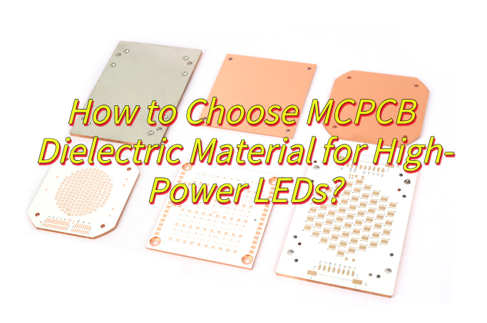
A metal core circuit board (MCPCB) is a specialized printed circuit board designed to solve one critical issue in modern electronics—heat. By replacing traditional FR4 with a thermally conductive metal base, MCPCBs significantly improve heat dissipation, making them essential for high-power and high-reliability applications.
Common Challenges in High-Power PCB Design
- Component Overheating
High-power components generate excessive heat, reducing efficiency and lifespan. - Thermal Fatigue Failures
Repeated heating cycles weaken solder joints and increase failure rates. - Limited Power Density
FR4 materials restrict compact, high-power layouts. - High Cooling Cost
External heat sinks and fans increase BOM and assembly complexity. - Supplier Instability
Difficulty finding a reliable partner for both prototyping and volume production.
Our Tailored MCPCB Solutions
- Efficient Heat Dissipation
Heat transfers directly through the metal base, improving thermal performance. - Extended Product Lifespan
Lower operating temperatures reduce stress and improve reliability. - Compact Design Support
Higher power density enables smaller and lighter products. - Reduced System Cost
Integrated thermal design reduces need for external cooling. - One-Stop Manufacturing
From prototype to mass production with stable quality and pricing.
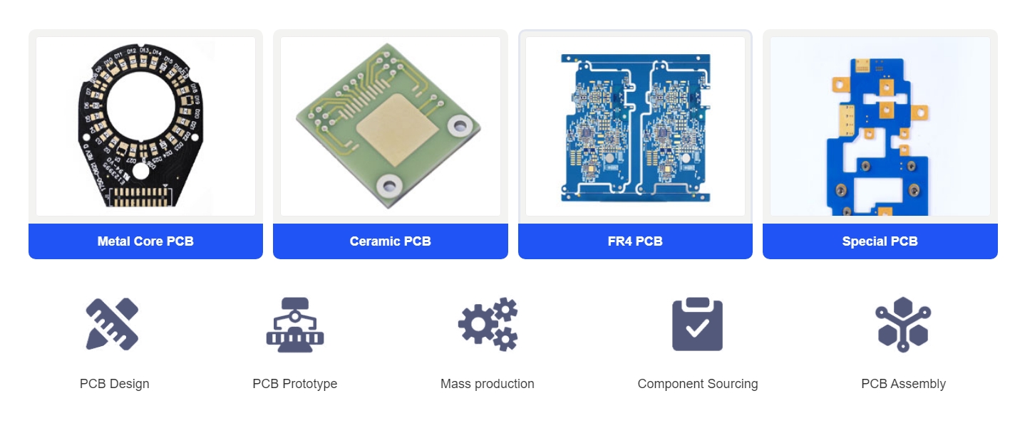
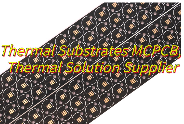
EBest Circuit is a professional metal core printed circuit board manufacturer specializing in high-performance thermal solutions. We support applications from LED lighting to telecom and automotive systems. Our strength lies in combining material expertise with strict process control. Whether you need a single double sided metal core printed circuit board prototype or large-scale production, we ensure consistent thermal and electrical performance. For fast quotation and engineering support, pls feel free to contact us via sales@bestpcbs.com.
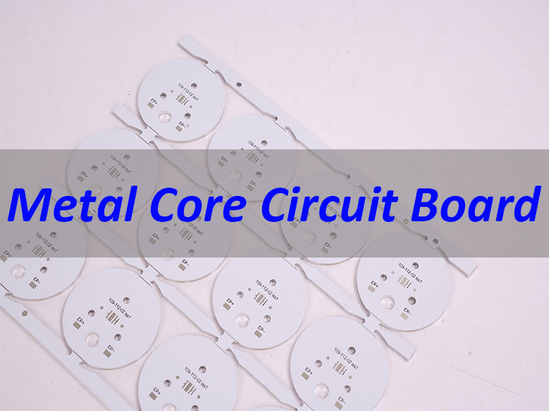
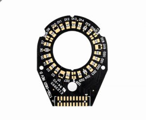
What Is a Metal Core Circuit Board?
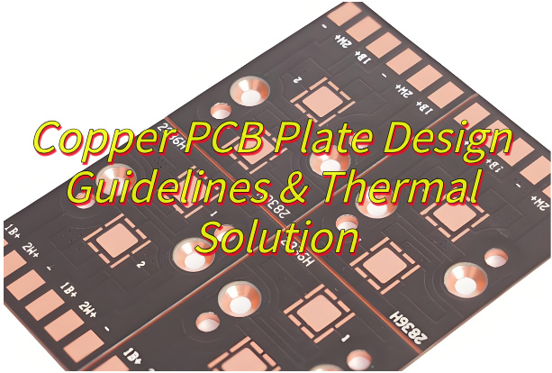
A metal core circuit board replaces the standard FR4 substrate with a metal base, typically aluminum or copper. This metal layer acts as a heat spreader, allowing heat to move away from critical components efficiently.
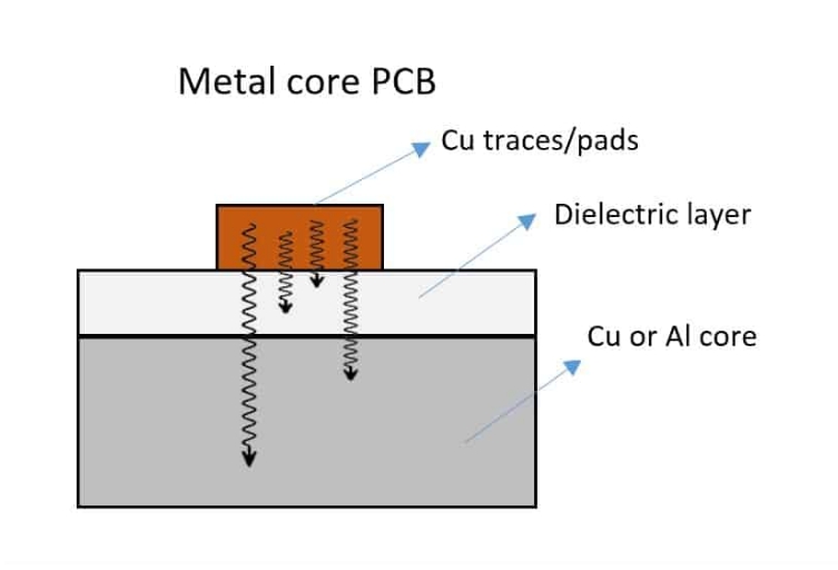
The typical MCPCB structure includes:
- Circuit Layer – Copper traces for electrical connection
- Dielectric Layer – Thermally conductive insulation
- Metal Core – Heat dissipation base
In practice, MCPCB integrates heat management directly into the PCB itself, making it ideal for high-power electronic designs.
Why Choose MCPCB Over FR4?
The key difference lies in thermal performance. FR4 is cost-effective but thermally inefficient, while MCPCB is designed specifically for heat management.
MCPCB vs FR4 Comparison
| Feature | FR4 PCB | Metal Core PCB | Design Impact |
|---|---|---|---|
| Thermal Conductivity | ~0.3 W/mK | 1–8+ W/mK | 3x–25x better heat transfer |
| Heat Dissipation | Poor | Excellent | Less external cooling needed |
| Mechanical Strength | Good | High | Better durability |
| Cost | Low | Higher | Used in high-power designs |
| Applications | General electronics | LED, power, automotive | Thermal-critical systems |
As a result, MCPCB is the preferred choice when heat directly impacts performance and reliability.
What Materials Are Used in MCPCB?
The performance of a metal core printed circuit board depends on three key materials:
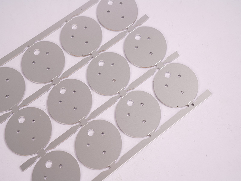
1. Metal Core
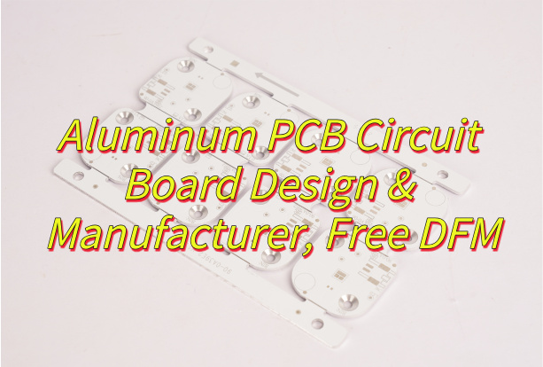
- Aluminum – Most common, cost-effective, good thermal performance
- Copper – Best thermal conductivity, higher cost
- Steel – Used for structural or shielding needs
2. Dielectric Layer
- Provides electrical insulation
- Transfers heat to metal core
- Typical conductivity: 1.0–8.0 W/mK
3. Copper Layer
- Forms electrical circuits
- Thickness varies based on current requirements
From a design perspective, selecting the right material combination directly determines thermal efficiency and reliability.
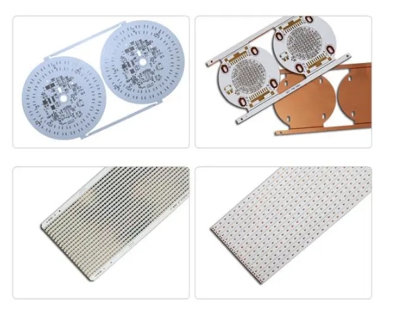
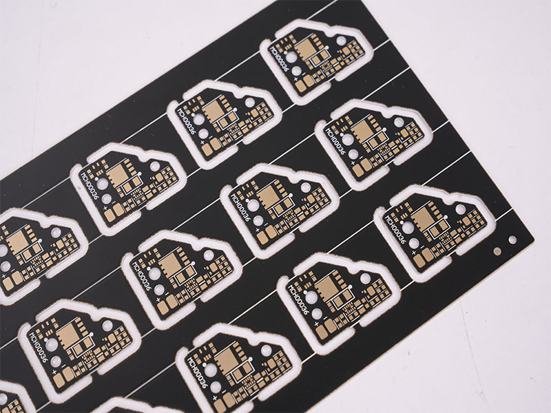
Types of Metal Core Circuit Boards
| Type | Structure | Key Benefit | Typical Use |
|---|---|---|---|
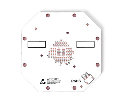
| Single-Sided | One copper layer | Low cost, high efficiency | LED modules |
| Double-Sided | Two copper layers | More routing flexibility | Power circuits |
| Multilayer | Multiple layers | High density design | RF, aerospace |
| Flexible MCPCB | Bendable structure | Space saving | Wearables |
In real applications, the choice depends on circuit complexity, thermal requirements, and budget.
How MCPCB Improves Thermal Management
MCPCB improves thermal performance by creating a direct heat path:
- Heat flows from component to copper layer
- Passes through dielectric layer
- Transfers into metal core
- Spreads across board surface
This significantly reduces thermal resistance and prevents hot spots.
For engineers, this means higher power handling, better reliability, and more compact designs.
Typical Applications of MCPCB
MCPCBs are widely used in heat-intensive applications:
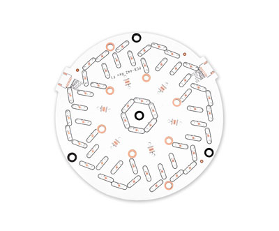
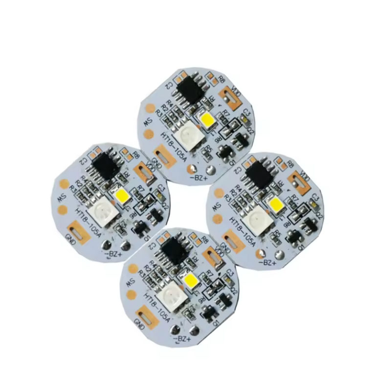
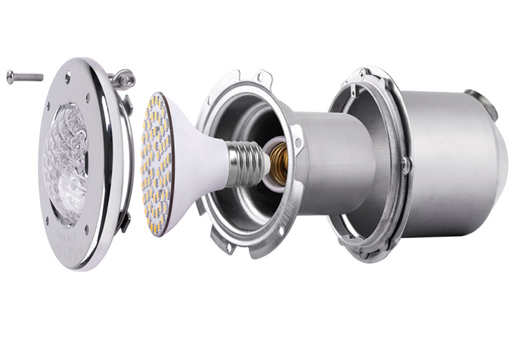
- LED Lighting – street lights, automotive headlights
- Power Electronics – converters, motor drivers
- Automotive Systems – ECU, battery modules
- Telecom & RF – power amplifiers, transmitters
- Industrial Equipment – inverters, control systems
In high-power scenarios, MCPCB is often the only practical solution to manage heat effectively.
How to Choose the Right Manufacturer
Selecting a reliable metal core circuit board manufacturer is critical.
Key Evaluation Points:
- Material Expertise – aluminum, copper, dielectric selection
- Process Capability – multilayer, heavy copper, thermal vias
- Prototype to Volume – seamless scaling
- Engineering Support – DFM and thermal design advice
- Certifications – ISO, automotive standards
This means your supplier should not just produce boards, but also optimize your thermal design.
Top Metal Core PCB Manufacturers in China
| Manufacturer | Strength | Best For |
|---|---|---|
| EBest Circuit | Large-scale production | High volume |
| Fastprint | Advanced PCB tech | HDI & IC |
| Sihui Fuji | LED specialization | Lighting |
| JLCPCB | Low-cost prototype | Startups |
| PCBCart | Engineering support | Custom design |
| Kinwong | Thermal expertise | High-reliability MCPCB |
In practice, the best choice depends on your project scale, complexity, and support needs.
What Affects MCPCB Cost?
Key cost drivers include:
- Material Type – copper vs aluminum
- Thermal Conductivity – higher = higher cost
- Layer Count – multilayer increases complexity
- Copper Thickness – heavy copper adds cost
- Board Size & Shape – affects material usage
- Order Volume – larger quantity reduces unit price
As a result, optimizing design early can significantly reduce total cost.
In short, a metal core circuit board is not just a PCB—it is a thermal solution. By integrating heat dissipation into the board itself, MCPCBs enable higher performance, longer lifespan, and more compact designs.
For projects that demand reliable thermal management, choosing the right partner is essential. EBest Circuit provides full support from prototype to mass production, ensuring your design meets both electrical and thermal requirements. Pls kindly note that free DFM and thermal design support available. A warm welcome to get a fast quote within 24 hours via sales@bestpcbs.com.
Technical FAQs About Metal Core Circuit Board
1. Why Is an Aluminum PCB More Reliable Than FR4 for LED Surgical Lights?
Aluminum PCBs are better suited for surgical lighting because their high thermal conductivity helps prevent lumen depreciation and color shifting during critical procedures. Unlike FR4, which tends to trap heat, an aluminum substrate quickly transfers thermal energy away from the LED dies. This helps maintain a stable junction temperature, so light output remains consistent and the color rendering index (CRI) stays reliable. For medical lighting, that level of stability is essential.
2. What Are the Primary Cost Drivers in MCPCB Manufacturing?
The cost of a metal core PCB is mainly influenced by the thermal conductivity of the dielectric layer and the choice of base material.
- Thermal conductivity of the dielectric layer:
High-performance dielectric materials, such as 3.0 W/mK and above, are usually much more expensive than standard 1.0 W/mK options. - Base material selection:
Copper substrates provide stronger thermal performance, but they are much more expensive and heavier than aluminum substrates. - Secondary processing requirements:
Extra processes such as ENIG surface finish, heavy copper foil, or complex mechanical routing for custom housings will also increase the total cost.
3. How Is Dielectric Breakdown Prevented in High-Voltage MCPCB Designs?
Dielectric breakdown is prevented by selecting an insulating layer with sufficient dielectric strength to handle the maximum operating voltage of the application. In power electronics and automotive systems, the insulation layer between the copper circuit and the metal base must provide stable electrical isolation. High-quality MCPCBs are often designed to pass Hi-Pot testing from 2000 VAC to 6000 VAC, depending on the dielectric thickness and material composition.
4. How Do Metal Core PCBs Perform in Extreme Outdoor Environments?
Metal core PCBs perform very well in harsh outdoor environments because they offer strong mechanical stability and excellent resistance to thermal shock. In applications such as street lights and construction warning lights, the metal base helps prevent warping during repeated temperature changes. At the same time, the rigid aluminum or copper core protects solder joints from cracking under vibration or physical impact, which is a common issue with traditional FR4 boards used outdoors.