PCB manufacturing PCB manufacturing
Home > Blog

copper busbar ampacity

Copper & Aluminum Busbar Ampacity, Sizing & Calculation Guide
Tuesday, April 7th, 2026

Key Basics of Busbar Ampacity & Sizing

Busbar ampacity (current-carrying capacity) and sizing are critical for safe, efficient electrical systems.

This guide breaks down calculations, charts, and best practices for copper and aluminum busbars—no unnecessary jargon.

As an electrical engineer, I’ll share actionable steps to avoid common mistakes in busbar design.
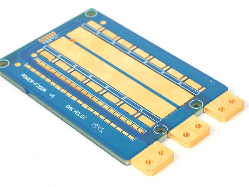
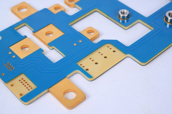
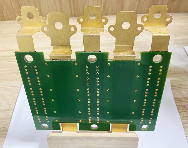
Copper Busbar

Copper Busbar Ampacity: Definition, Standards & Typical Values

What Is Copper Busbar Ampacity?

Copper busbar ampacity is the maximum continuous current a copper busbar can carry without exceeding safe temperature limits.

ANSI C37.20 specifies a 65K temperature rise for silver-plated copper busbars (at 40°C ambient) and 30K for non-plated options.

Typical Copper Busbar Ampacity Ratings (Open Air, 35°C Ambient)

Copper Busbar Size (mm)Ampacity (A) – Vertical MountAmpacity (A) – Horizontal MountTypical Current Density (A/mm²)
10×31201144.0
25×63803592.5
50×66806462.3
100×10185017581.85

Aluminum Busbar Ampacity: How It Compares to Copper

Aluminum vs. Copper Busbar Ampacity: Key Differences

Aluminum busbars have lower conductivity than copper, so they require larger cross-sections to achieve the same ampacity.

A copper busbar’s ampacity is roughly 1.27 times that of an aluminum busbar with the same cross-sectional area.

Aluminum Busbar Ampacity Chart (Open Air, 35°C Ambient)

Aluminum Busbar Size (mm)Ampacity (A) – Vertical MountAmpacity (A) – Horizontal MountCurrent Density (A/mm²)
10×395903.2
25×63002852.0
50×65305041.8
100×10145013781.45

Copper Busbar Size Calculation Formula: Step-by-Step Guide

Core Formula for Copper Busbar Sizing

The primary formula for copper busbar cross-sectional area (S) is: S = I / k

Where I = rated current (A), and k = current density (A/mm²).

For standard applications, use k = 1.8–2.0 A/mm² for bare copper and 2.0–2.5 for silver-plated copper.

Example: Calculate Copper Busbar Size for 3000A

Using k = 2.5 (for silver-plated copper): S = 3000 / 2.5 = 1200 mm².

A 120x10mm copper busbar (1200 mm²) meets this requirement for 3000A applications.

Busbar Current Density: Typical Values & Calculations

What Is Busbar Current Density?

Current density (A/mm²) is the amount of current per unit of the busbar’s cross-sectional area.

It directly impacts temperature rise—higher density equals more heat, which reduces the busbar’s lifespan.

Typical Current Density for Copper Busbars

  • Natural convection: 1.5–2.0 A/mm² (for continuous operation)
  • Open air: 2.0–2.5 A/mm² (for short-term loads)
  • Bolted joints: Maximum 1.0 A/mm² at contact surfaces to avoid overheating

Busbar Sizing Calculation for Current Carrying Capacity & Temperature Rise

Factors Affecting Temperature Rise

Temperature rise depends on current density, busbar size, mounting orientation, and ambient temperature.

Use the formula: I²R = Kt × A × ΔT, where ΔT = temperature rise (K).

Temperature Rise Correction for Ambient Conditions

For ambient temperatures above 35°C, use the correction factor.

Example: At 45°C ambient, reduce ampacity by approximately 9.5%.

Busbar Ampacity NEC Standards & Compliance

The NEC (National Electrical Code) provides guidelines for busbar ampacity to ensure safety and compliance.

The NEC requires busbars to be sized for their maximum continuous current, with derating for multiple busbars.

Bolted copper busbar joints must meet NEC contact resistance limits to prevent overheating.

Busbar Application Cases: Medical, Aerospace & Industrial Equipment

Medical Equipment (MRI Machines)

MRI machines require low-resistance copper busbars (100x10mm) with 1850A ampacity and 1.85 A/mm² density.

Bolted joints use silver plating to maintain contact integrity and avoid interference with magnetic fields.

Aerospace (Satellite Power Systems)

Satellites use flexible copper busbars with a 50x6mm size, 680A ampacity, and a short-circuit withstand capacity of 50kA/3s.

Lightweight design prioritizes current density (2.3 A/mm²) and corrosion resistance for space environments.

Industrial Equipment (High-Voltage Switchgear)

Industrial high-voltage switchgear uses 100x10mm copper busbars (1850A ampacity) for a 3000A rated current.

Double-layer busbars boost ampacity to 2923A, meeting industrial power demands.

Copper Busbar Weight Calculation Formula

Copper busbar weight is calculated using: Weight (kg) = Cross-Sectional Area (mm²) × Length (m) × 0.00896.

Example: A 100x10mm copper busbar, 1m long: 1000 × 1 × 0.00896 = 8.96 kg.

This formula aids in material planning and load-bearing design for electrical enclosures.

Bolted Copper Busbar Joints: Torque Specs & Contact Density

Bolt Torque Specifications

M10 bolts require 17.7–22.6 N·m of torque; M16 bolts require 78.5–98.1 N·m for secure joints.

A torque deviation exceeding 20% causes uneven pressure and increased contact resistance.

Contact Surface Current Density

Bolted joint contact surfaces must not exceed 1.0 A/mm² to prevent overheating and oxidation.

Apply conductive antioxidant to reduce contact resistance by 30–50% and protect against corrosion.

Busbar Ampacity Calculator: How to Use & Key Inputs

Essential Inputs for Busbar Ampacity Calculators

  • Busbar material (copper/aluminum), size (mm), and mounting orientation (vertical/horizontal)
  • Ambient temperature and installation type (open air/natural convection)
  • Rated current (A) and short-circuit duration (s) for thermal stability

How to Verify Calculator Results

Cross-check calculator outputs with DIN43671 or NEC standards to ensure accuracy.

For critical applications, validate results with thermal testing to confirm temperature rise limits.

FAQ: Common Busbar Ampacity & Sizing Questions

1. How to calculate copper busbar current carrying capacity?

Use the formula I = S × k, where S = cross-sectional area and k = current density for copper.

Adjust for ambient temperature and mounting orientation using correction factors.

2. What is the typical current density for copper busbar in natural convection?

The typical current density for copper busbars in natural convection is 1.5–2.0 A/mm² for continuous operation.

Exceeding this value will cause excessive temperature rise and reduce busbar reliability.

3. How does busbar size affect ampacity?

A larger busbar size (greater cross-sectional area) increases ampacity by improving heat dissipation.

A 50x6mm copper busbar (300 mm²) has 680A ampacity, while a 100x10mm busbar (1000 mm²) has 1850A.

4. What is the short circuit withstand capacity of a 50×6 mm copper busbar?

A 50x6mm copper busbar typically has a short-circuit withstand capacity of 50kA for 3 seconds.

This meets industrial standards for most medium-voltage applications.

5. How do I derate busbar ampacity for multiple busbars?

For double-layer busbars, derate by 1.5x; for triple-layer busbars, derate by 2.0x the single-layer ampacity.

Ensure a 3mm gap between busbars to maintain proper heat dissipation.

6. What is the difference between copper and aluminum busbar ampacity?

Copper busbars have 25–30% higher ampacity than aluminum busbars of the same size.

Aluminum requires a 1.27x larger cross-section to match copper’s current-carrying capacity.

Conclusion: Choose the Right Busbar Solution for Your Project

Proper busbar sizing, ampacity calculation, and material selection are critical for safe, efficient electrical systems.

Whether you need copper busbars for lithium batteries, aerospace, medical, or industrial equipment, we have you covered.

If you require high-quality copper or aluminum busbars, custom sizing, or technical support, we deliver reliable, compliant solutions tailored to your needs.

You may also like

Copper Busbar Current Carrying Capacity: Complete Guide (ANSI/IEC)
Friday, January 23rd, 2026

Copper busbar current carrying capacity (ampacity) is the maximum electrical current a copper busbar can safely conduct without overheating or failure, a critical parameter for electrical panel and power distribution design. Following ANSI C119.2 and IEC 60364 standards ensures copper busbar current carrying capacity meets industrial safety requirements, avoiding fire or equipment damage risks. This guide breaks down calculation methods, key influencing factors, and compliance checks for copper busbar current carrying capacity to help engineers make accurate decisions.

What Is Copper Busbar Current Carrying Capacity (Ampacity)?

Copper busbar current carrying capacity, also known as ampacity, refers to the maximum RMS current a copper busbar can carry continuously under specific environmental conditions (temperature, humidity, installation space). Unlike theoretical conductivity, practical ampacity accounts for heat dissipation, material resistivity, and long-term operational stability—key to preventing overheating in high-voltage applications.

How to Calculate Copper Busbar Current Carrying Capacity (Step-by-Step Formula)

The core formula for copper busbar ampacity calculation (per ANSI C119.2) is:
I = (k × A × ΔT^0.5) / L
– I = Current carrying capacity (amps)
– k = Material constant (5.7 for pure copper)
– A = Cross-sectional area (mm²)
– ΔT = Allowable temperature rise (°C, typically 30-60°C)
– L = Busbar length (meters)

This formula prioritizes real-world heat dissipation, not just theoretical conductivity. For 10x100mm copper busbars (1000mm²), the baseline ampacity is 2500A at 40°C ambient temperature—adjust for installation (air vs. enclosed) by ±15%.

Key Factors Affecting Copper Busbar Ampacity

Temperature (Ambient & Operating)

Ambient temperature directly impacts copper busbar current carrying capacity: every 10°C increase above 40°C reduces ampacity by 8-10%. For example, a copper busbar rated 2000A at 40°C only carries 1800A at 50°C. Operating temperature (from internal resistance) must stay below 90°C to avoid material degradation.

Busbar Size & Installation Method

  • Thicker busbars (≥10mm) have 20% higher ampacity than thin ones (≤5mm) of the same width, due to better heat dissipation.
  • Open-air installation increases ampacity by 15% vs. enclosed panels (common in switchgear).

Copper Busbar Current Rating Comparison (By Material/Thickness)

Copper Busbar SpecificationCross-Section (mm²)Ampacity at 40°C (A)Ampacity at 50°C (A)
5x50mm Pure Copper250800720
10x100mm Pure Copper100025002250
10x100mm Tinned Copper100024502205

Tinned copper busbars have slightly lower copper busbar current carrying capacity (2-3%) but better corrosion resistance—ideal for outdoor applications.

ANSI vs IEC: Copper Busbar Ampacity Standards Differences

ANSI C119.2 (US standard) uses 30°C ambient temperature as baseline, while IEC 60364 (EU standard) uses 40°C. This means a 10x100mm copper busbar rated 2600A per ANSI is only 2500A per IEC. Always align with regional standards to ensure copper busbar current carrying capacity compliance.

Common Mistakes in Copper Busbar Ampacity Calculation

  1. Ignoring ambient temperature: Using 40°C ratings for high-temperature environments (e.g., industrial plants) leads to 10-15% overload risk.
  2. Overlooking installation method: Enclosed panels require derating ampacity by 15%.
  3. Using theoretical conductivity instead of practical ampacity: Leads to inaccurate sizing and safety hazards.

FAQ: Copper Busbar Current Carrying Capacity (Engineer-Answered)

Q1: What is the maximum current a 10x100mm copper busbar can carry?

A 10x100mm pure copper busbar has a maximum copper busbar current carrying capacity of 2500A at 40°C (open-air installation). For enclosed panels, derate to 2125A; at 50°C, derate to 2250A.

Q2: How to adjust ampacity for high-temperature environments?

Use the temperature correction factor: For every 5°C above 40°C, multiply baseline ampacity by 0.95. For 60°C ambient, correction factor = 0.85 (2500A × 0.85 = 2125A).

Q3: Does coating affect copper busbar current capacity?

Non-conductive coatings (e.g., epoxy) reduce heat dissipation, lowering copper busbar current carrying capacity by 5-8%. Conductive coatings (e.g., tin plating) have minimal impact (≤3%).

Q4: What is the safety margin for copper busbar ampacity?

Industry best practice is a 15-20% safety margin: If your system requires 2000A, select a copper busbar with 2400A rated copper busbar current carrying capacity to account for voltage fluctuations and temperature spikes.

Q5: How to verify copper busbar ampacity compliance?

Use thermal imaging to check operating temperature (must be <90°C) and cross-verify with ANSI/IEC calculation formulas. Third-party testing (per UL 857) further validates compliance.

How to Select the Right Copper Busbar for Your Ampacity Needs

  1. Calculate required ampacity (including safety margin).
  2. Adjust for ambient temperature and installation method.
  3. Align with regional standards (ANSI/IEC).
  4. Choose material (pure/tinned copper) based on application environment.

Our engineering team provides free copper busbar current carrying capacity calculation support to ensure optimal sizing.

Our Copper Busbar Solutions for Reliable Current Carrying Capacity

We manufacture high-purity copper busbars (99.99% copper content) with precise copper busbar current carrying capacity ratings, compliant with ANSI and IEC standards. Whether you need custom sizes (5x50mm to 20x200mm) or tinned/epoxy-coated options, our products meet your exact ampacity requirements.

If you need reliable copper busbar current carrying capacity solutions for your electrical projects, place an order with us today. Contact our sales team via email: sales@bestpcbs.com.

You may also like

How to Calculate Copper Busbar Ampacity?
Friday, August 29th, 2025

How to calculate copper busbar ampacity? This guide covers calculation methods, sizing charts (including 12x4mm), and comparisons with aluminum, providing datasheet for electrical system design.

Are you troubled with these questions?

  • High electricity bills?
  • Overheating issues?
  • Slow custom orders?

EBest Circuit (Best Technology) can provide you service and solution:

  • Save energy – 15% lower resistance, higher efficiency.
  • Cooler operation – 20% better heat dissipation, longer lifespan.
  • Faster delivery – 72-hour custom production, no delays.

Welcome to contact us if you have any request for copper busbar: sales@bestpcbs.com.

What Is Copper Busbar Ampacity?

Copper Busbar Ampacity refers to the maximum continuous current a copper busbar can safely carry under specific environmental conditions (e.g., temperature, heat dissipation, insulation level). It is determined by factors like cross-sectional area, copper purity, surface treatment, and installation methods (such as dense packing or ventilation).

How to Calculate Copper Busbar Ampacity?

Methods about how to calculate copper busbar ampacity:

1. Cross-Sectional Area Estimation (Single Busbar)

  • Formula: I=W×K
  • W: Busbar width (mm)
  • K: Thickness factor (e.g., 18 for 10mm thickness)

2. Multi-Layer Busbar Correction

  • Double-Layer: Idouble​=Isingle​×1.58
  • Triple-Layer: Itriple​=Isingle​×2

3. Temperature Correction

  • Lower Temperature (e.g., 25℃): Icorrected​=I40​×1.18
  • Higher Temperature (e.g., >40℃):Icorrected​=I40​×0.9

4. Simplified Formula

  • Formula: I=W×(T+8.5)
  • W: Busbar width (mm)
  • T: Busbar thickness (mm)

5. Environmental & Installation Adjustments

Parallel Busbars (AC):

  • 2 bars: I×0.8
  • 3 bars: I×0.7
  • 4 bars: I×0.6

6. Copper vs. Aluminum Conversion

Formula: Icopper​=Ialuminum​×1.3

7. Practical Recommendations

  • Refer to Tables: Use standards like Industrial and Civil Power Distribution Design Manual for precision.
  • Safety Margin: Design with 10–20% reserve capacity.
  • Temperature Monitoring: Ensure long-term temperature rise ≤70K (Class F insulation) to prevent aging.

What is the Ampacity of a 12 x 4 Copper Busbar?

For a 12×4mm copper busbar (40℃ ambient, ΔT≤50K):‌

  • Vertical mounting‌: ‌~320A‌ (bare copper).
  • Horizontal mounting‌: ‌~280A‌ (12% reduced heat dissipation).

Key adjustments‌:

  • Tin-plated surface: ‌+8%‌ (→345A vertical).
  • 60℃ ambient: ‌Derate 30%‌ (→~224A).
What is the Ampacity of a 12 x 4 Copper Busbar?

Copper Busbar Ampacity Table in MM

Busbar Size
(Width × Thickness, mm)‌
‌Ampacity(Vertical, A)‌Ampacity
(Horizontal, A)‌
Horizontal Reduction Factor‌
15 × 3               1651450.88
20 × 52902550.88
30 × 44003600.90
40 × 55404850.90
50 × 67406650.90
60 × 69008000.89
80 × 81,4001,2600.90
100 × 102,3002,0500.89
120 × 122,9002,6000.90

Copper Busbar DC Ampacity Chart

Copper Busbar Dimensions (Width × Thickness, mm)Single-Layer Ampacity (A)Double-Layer Ampacity (A)Triple-Layer Ampacity (A)
40 × 4480750960
60 × 68401,3441,722
80 × 81,2802,0002,560
100 × 101,8102,8243,620

Copper vs Aluminum Busbar Ampacity

Conductivity & Ampacity

  • Copper Busbar: Higher conductivity (58 MS/m). Ampacity ~1.43× aluminum for same dimensions. Supports 2-4A/mm².
  • Aluminum Busbar: Lower conductivity (35-37.7 MS/m). Requires ~30% larger cross-section to match copper’s ampacity. Supports 3-5A/mm².

Physical Properties

ParameterCopperAluminum
Density8.9g/cm³ (3.3× aluminum)2.7g/cm³
Thermal Expansion16.5ppm/°C23.1ppm/°C
Melting Point1,085°C660°C

Mechanical Performance

  • Copper Busbar: Higher strength, resistant to deformation/creep. Ideal for high-stress environments.
  • Aluminum Busbar: Softer, prone to creep. Requires surface treatment (e.g., tin plating) to reduce contact resistance.

Cost & Weight

  • Copper Busbar: 2-3× higher cost per ampacity unit. Heavier (3.3× aluminum).
  • Aluminum Busbar: ~40% cheaper. Lightweight (1/3 of copper’s weight).

Environmental Adaptability

  • Copper Busbar: Stable at high temps (40°C ampacity = 85% of 25°C). Low oxidation impact.
  • Aluminum Busbar: Sensitive to temp rise (40°C ampacity = 70-85% of 25°C). Forms high-resistance oxides.

Safety & Application

  • Copper Busbar: Higher melting point reduces arc risks. Critical for data centers/substations.
  • Aluminum Busbar: Lower melting point increases arc hazards. Suitable for residential/light industry.

Trade-offs

  • Copper Busbar: Compact, durable, high ampacity. Expensive, heavy.
  • Aluminum Busbar: Cost-effective, lightweight. Requires larger size, frequent maintenance.
Copper vs Aluminum Busbar Ampacity

Why Choose EBest Circuit (Best Technology) as Copper Busbar PCB Manufacturer?

Reasons why choose us as copper busbar PCB manufacturer:

  • Global Quality Certifications: ISO 9001 (quality management), ISO 14001 (environmental management).UL certification for flame resistance and current-carrying capacity.
  • Competitive Pricing: Direct factory pricing with no middlemen, reducing costs by 15-20% compared to industry averages.
  • Fast Lead Times: 24-hour prototype delivery for standard designs; 98% on-time delivery rate for bulk orders (500+ units).
  • Premium Material Quality: Uses 99.9% purity copper (T2 grade) with third-party material certification.
  • Advanced PCBA Integration: In-house SMT assembly lines supporting 0201 components and 0.3mm pitch BGAs.
  • One-Stop Service: Covers design optimization → prototyping → mass production → PCBA assembly → testing.
  • Rigorous QC Processes: 4-stage inspection: incoming material check → in-process monitoring → final electrical test → aging test.
  • Customization Flexibility: Supports multi-layer busbars (up to 6 layers) and complex geometries; Accepts small-batch orders (as low as 10 units) with no MOQ restrictions.
  • Engineering Support: Free DFM (Design for Manufacturability) analysis to optimize cost and performance. And 24/7 technical support via email/phone for troubleshooting.
Why Choose EBest Circuit (Best Technology) as Copper Busbar PCB Manufacturer?

Our Busbar PCB Capabilities

ParameterValue/Description
Copper Bar Spacing0.8-1.0mm
Copper Thickness1.0mm-3.0mm
Current Carrying Capacity50-300A
BendabilityCustomizable bending upon request
Surface Finishing OptionsENIG (Electroless Nickel Immersion Gold), Immersion Silver, Gold Plating
Board Thickness3.0-6.0mm
Hole Wall Thickness≥25μm
Aspect Ratio1:6 or 1:7 (for 1.0mm copper thickness with minimum 0.7mm hole diameter)
Layer CountTypical 3-4 layers; additional layers require design evaluation
Maximum DimensionsStandard: 600×400mm; Double-sided: 900×600mm
Lead Time3-4 layers: 13-15 days; add 3 days per layer beyond 4 layers

How to Get A Quote For Copper Busbar PCB Project?

Materials Required for Accurate Quotation:

Design Files

  • 2D CAD drawings (DXF/DWG) or 3D models (STEP/IGES).
  • Cross-sectional busbar dimensions (width × thickness).

Technical Specifications

  • Current rating (amps) and allowable temperature rise.
  • Copper material grade (e.g., T2, C110).
  • Surface finish requirements (e.g., tin plating, nickel).

Production Details

  • Order quantity (prototypes/bulk).
  • Lead time expectations (urgent/standard).

Additional Requirements

  • Certifications (UL, RoHS).
  • Special testing (e.g., hi-pot, thermal cycling).
  • Packaging preferences (anti-static, custom boxing).

Welcome to contact us if you have any request for copper busbar PCB: sales@bestpcbs.com.

You may also like