





Key Takeaways
- Busbar ampacity is the maximum continuous current a busbar can carry under specified installation and temperature conditions.
- Copper busbars offer higher electrical conductivity and generally require smaller cross-sections than aluminum for comparable resistance.
- Busbar sizing calculations begin with current, conductor area, and current density, followed by thermal and short-circuit verification.
- Temperature rise, ventilation, installation orientation, and joint resistance can substantially change actual current-carrying capacity.
- Busbar ampacity charts are useful for preliminary selection, but final ratings must reflect the actual equipment configuration.
Busbar ampacity determines how much electrical current a copper or aluminum busbar can safely carry without exceeding its allowable operating temperature. The correct busbar size depends on conductor material, cross-sectional area, ambient temperature, ventilation, installation method, and electrical loading.
For engineers designing power distribution systems, battery connections, industrial equipment, or high-current PCB assemblies, selecting a busbar involves more than matching its dimensions to a current rating. This guide explains the calculation formulas, copper and aluminum differences, practical sizing examples, and verification methods needed to select an appropriate conductor.
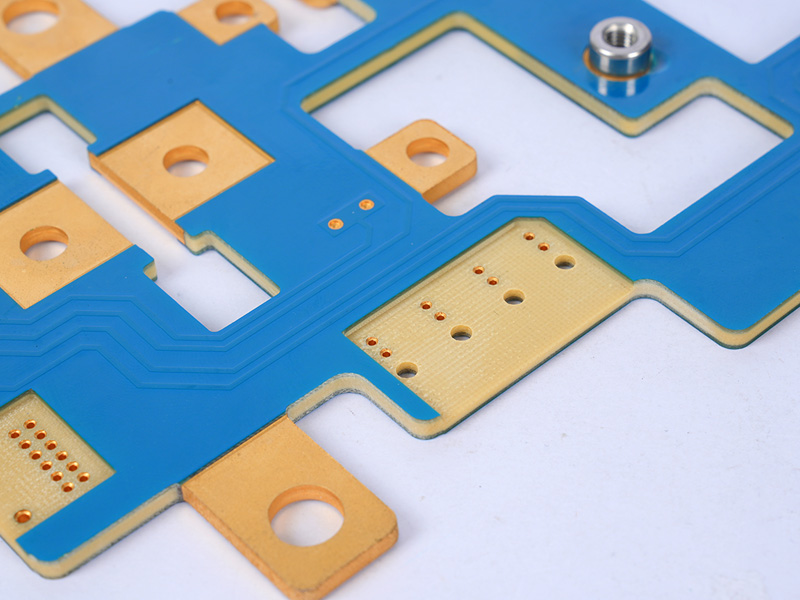
What Is Busbar Ampacity?
Busbar ampacity is the maximum continuous current that a busbar can carry without exceeding the applicable temperature limits under defined operating conditions. It represents the conductor’s usable current-carrying capacity rather than a fixed electrical property of copper or aluminum.
When current flows through a busbar, electrical resistance produces heat. At steady state, the conductor temperature stabilizes when the heat generated equals the heat transferred to its surroundings.
The main factors affecting busbar ampacity include:
- Conductor material: Copper and aluminum have different electrical resistivity and thermal properties.
- Cross-sectional area: Larger conductor sections generally have lower electrical resistance.
- Surface area: Wider, thinner bars may dissipate heat differently from narrower, thicker bars of equal cross-sectional area.
- Ambient temperature: Higher surrounding temperatures reduce the available temperature-rise margin.
- Installation method: Vertical or horizontal positioning, nearby conductors, and ventilation affect cooling.
- Electrical connections: Contact resistance at bolted or welded joints can create localized heating.
For example, a 50 × 10 mm copper busbar has a cross-sectional area of 500 mm². Its continuous current rating cannot be established from that dimension alone. A bar operating in ventilated open air may support a different current than the same bar enclosed in a compact electrical cabinet.
This distinction is particularly important when comparing busbar ratings from different manufacturers.
How Does Copper Busbar Ampacity Compare with Aluminum?
Copper busbars generally provide lower electrical resistance than aluminum busbars of the same dimensions. Aluminum offers lower weight and may provide a more economical solution when sufficient installation space is available.
At approximately 20°C, common reference values are:
| Property | Copper | Aluminum |
|---|---|---|
| Electrical resistivity | 0.0172 Ω·mm²/m | 0.0282 Ω·mm²/m |
| Electrical conductivity | Approx. 58 MS/m | Approx. 35 MS/m |
| Density | 8.96 g/cm³ | 2.70 g/cm³ |
| Thermal conductivity | Approx. 400 W/m·K | Approx. 235 W/m·K |
| Relative conductor weight | Higher | Lower |
| Typical selection priority | Compactness, lower resistance | Weight and material cost |
Values are approximate references for high-conductivity copper and electrical-grade aluminum. Actual properties vary with alloy, purity, temper, and temperature.
For equal dimensions and temperature, aluminum has approximately 1.64 times the electrical resistance of copper. To obtain similar conductor resistance over the same length, an aluminum bar would need approximately 1.64 times the copper cross-sectional area, assuming the reference resistivities above.
However, this ratio describes electrical resistance, not an ampacity conversion factor. Actual current ratings also depend on heat dissipation, conductor geometry, surface treatment, and installation conditions.
When to choose copper: Copper is often preferred for compact switchgear, power electronics, battery connections, and equipment where low resistance and limited installation space are important.
When to choose aluminum: Aluminum can be advantageous for larger power distribution systems, weight-sensitive installations, and projects where a larger conductor section can be accommodated. Its joints require suitable connection materials, surface preparation, and measures to manage oxidation and differential thermal expansion.
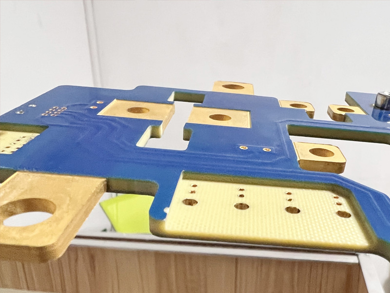
How Do You Calculate Busbar Current Carrying Capacity?
A preliminary busbar current carrying capacity calculation uses conductor cross-sectional area and an assumed design current density.
The basic relationship is:
Where:
- I = current in amperes (A)
- J = assumed current density (A/mm²)
- A = conductor cross-sectional area (mm²)
For a rectangular busbar:
Where W is the busbar width and T is its thickness, both in millimeters.
Example: 50 × 10 mm copper busbar
Assume a preliminary design current density of 1.5 A/mm².
The estimated current is 750 A under the assumed current-density criterion. This is a preliminary sizing result, not a verified continuous ampacity rating.
To confirm whether the busbar can carry 750 A continuously, the designer must evaluate its actual temperature rise, installation environment, joints, and applicable equipment requirements.
The current-density method is useful for quickly comparing potential conductor sizes. For final selection, it should be supported by manufacturer test data, validated thermal calculations, or appropriate temperature-rise testing.
What Is the Busbar Sizing Calculation Formula?
The commonly used preliminary busbar sizing formula is:
This calculates the cross-sectional area required for a selected design current and assumed current density.
Example: Calculating copper busbar size for 1000 A
Assume a design current density of 1.5 A/mm².
The preliminary area requirement is approximately 667 mm².
Possible standard rectangular dimensions include:
| Copper busbar size | Cross-sectional area | Current density at 1000 A |
|---|---|---|
| 50 × 10 mm | 500 mm² | 2.00 A/mm² |
| 60 × 10 mm | 600 mm² | 1.67 A/mm² |
| 80 × 10 mm | 800 mm² | 1.25 A/mm² |
| 100 × 10 mm | 1000 mm² | 1.00 A/mm² |
Under the 1.5 A/mm² preliminary criterion, an 80 × 10 mm copper busbar provides sufficient cross-sectional area for further evaluation.
The actual selection must then consider temperature rise, enclosure ventilation, physical clearance, and connection design. An 80 × 10 mm bar is a candidate size rather than a guaranteed 1000 A solution.
For aluminum, the same formula can be used with a separately selected current-density assumption appropriate to the aluminum grade and installation conditions. A copper design value should not automatically be transferred to aluminum.
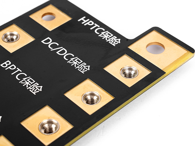
What Is the Recommended Current Density for Copper and Aluminum Busbars?
Busbar current density describes the amount of electrical current passing through each square millimeter of conductor cross-section.
A higher current density allows a smaller conductor but generally increases electrical heating per unit length. The allowable value depends on the surrounding thermal conditions and the conductor’s construction.
For an initial feasibility estimate, engineers sometimes use planning assumptions such as those below.
| Material | Illustrative design current density | Design considerations |
|---|---|---|
| Copper | 1.0–1.5 A/mm² | Conservative initial sizing for selected naturally cooled arrangements |
| Copper | 1.5–2.0 A/mm² | Requires assessment of conductor geometry and available cooling |
| Aluminum | 0.6–1.0 A/mm² | Initial screening where lower conductor resistance per unit length is desired |
| Aluminum | 1.0–1.5 A/mm² | Requires installation-specific thermal verification |
These are illustrative engineering assumptions, not standardized or universally permissible current-density limits. They are not a substitute for a validated ampacity table.
A useful way to understand current density is to compare two copper conductors carrying the same load.
At 1000 A, a 50 × 10 mm copper bar operates at 2.0 A/mm², while a 100 × 10 mm bar operates at 1.0 A/mm². The larger conductor has lower resistance per meter, which reduces resistive losses.
Nevertheless, conductor surface area and cooling conditions also change with geometry. Current density alone cannot predict the final steady-state temperature.
Copper and Aluminum Busbar Size Chart
A busbar size chart is most useful when it clearly distinguishes conductor dimensions, cross-sectional area, and an assumed current-density calculation from actual tested ampacity.
The following tables give illustrative currents calculated from fixed current-density assumptions, rather than certified current ratings.
Copper busbar preliminary sizing chart
Assumption: J=1.5 A/mm²
| Copper busbar size | Area (mm²) | Calculated current (A) |
|---|---|---|
| 20 × 3 mm | 60 | 90 |
| 25 × 5 mm | 125 | 188 |
| 30 × 5 mm | 150 | 225 |
| 40 × 5 mm | 200 | 300 |
| 50 × 6 mm | 300 | 450 |
| 50 × 10 mm | 500 | 750 |
| 60 × 10 mm | 600 | 900 |
| 80 × 10 mm | 800 | 1200 |
| 100 × 10 mm | 1000 | 1500 |
| 120 × 10 mm | 1200 | 1800 |
Aluminum busbar preliminary sizing chart
Assumption: J=1.0 A/mm²
| Aluminum busbar size | Area (mm²) | Calculated current (A) |
|---|---|---|
| 20 × 3 mm | 60 | 60 |
| 25 × 5 mm | 125 | 125 |
| 30 × 5 mm | 150 | 150 |
| 40 × 5 mm | 200 | 200 |
| 50 × 6 mm | 300 | 300 |
| 50 × 10 mm | 500 | 500 |
| 60 × 10 mm | 600 | 600 |
| 80 × 10 mm | 800 | 800 |
| 100 × 10 mm | 1000 | 1000 |
| 120 × 10 mm | 1200 | 1200 |
The calculated values are intended for early-stage conductor comparisons. They do not account for ambient temperature, enclosure design, surface finish, conductor grouping, AC effects, or joint temperatures.
For actual product ratings, use documented test conditions or a validated thermal model. Manufacturer tables should also be checked for the specific conductor arrangement, since a busbar mounted edgewise can cool differently from one mounted flat.
How Does Temperature Rise Affect Busbar Ampacity?
Temperature rise is one of the most important factors in busbar ampacity because it determines whether a conductor can safely carry its rated current during continuous operation.
As current passes through the busbar, electrical resistance generates heat. The heat produced per unit time is calculated using:
Where:
- P = electrical power loss (W)
- I = current (A)
- R = conductor resistance (Ω)
For a uniform busbar, resistance can be estimated as:
Where ρ is electrical resistivity, L is conductor length, and A is cross-sectional area.
Example: Heat generated by a 100 × 10 mm copper busbar
Assume a copper busbar with the following conditions:
- Width: 100 mm
- Thickness: 10 mm
- Length: 1 m
- Current: 1000 A
- Electrical resistivity: 0.0172 Ω·mm²/m at 20°C
Its resistance at 20°C is:
The resulting power loss is:
Therefore, the busbar produces approximately 17.2 W of resistive heat per meter at the reference temperature.
As conductor temperature increases, copper resistance rises, increasing electrical losses. The actual steady-state temperature depends on heat transfer through convection, radiation, and conduction into connected components.
For copper, the temperature dependence of resistance can be approximated by:
Where α is approximately 0.00393/°C near 20°C for common electrical-grade copper.
At 80°C, the example conductor’s estimated resistance is approximately 23.6% higher than at 20°C, producing approximately 21.3 W/m of resistive loss at the same current.
How ambient temperature changes busbar selection
A conductor operating at 25°C ambient has more thermal margin than the same conductor operating at 50°C ambient, assuming identical maximum allowable temperatures and cooling conditions.
For this reason, engineers must consider the actual operating environment rather than relying on a single ampacity chart.
In enclosed installations, neighboring electrical components, restricted airflow, and nearby busbars can further increase operating temperature. For applicable low-voltage assemblies, temperature-rise verification should follow the relevant IEC 61439 requirements.
How Do You Size a Busbar for 3000A?
A 3000A busbar should be sized by establishing the required conductor area, comparing feasible conductor arrangements, and verifying temperature rise and short-circuit performance.
Step 1: Estimate the required cross-sectional area
Assume a preliminary copper current density of 1.5 A/mm²:
The initial calculation indicates a total copper cross-sectional area of 2000 mm².
Step 2: Compare potential conductor configurations
| Busbar arrangement | Total area | Calculated current density |
|---|---|---|
| 1 × 100 × 10 mm | 1000 mm² | 3.00 A/mm² |
| 1 × 120 × 10 mm | 1200 mm² | 2.50 A/mm² |
| 2 × 100 × 10 mm | 2000 mm² | 1.50 A/mm² |
| 2 × 120 × 10 mm | 2400 mm² | 1.25 A/mm² |
| 3 × 80 × 10 mm | 2400 mm² | 1.25 A/mm² |
The 2000 mm² and 2400 mm² arrangements satisfy the assumed preliminary area criterion. However, their thermal performance depends on the spacing between parallel conductors, enclosure airflow, joint configuration, and how current divides between the bars.
Step 3: Verify the complete arrangement
Parallel conductors do not necessarily provide a linear increase in current-carrying capacity. Closely spaced bars can heat one another, while AC skin and proximity effects may cause additional losses and uneven current distribution.
For a 3000A installation, the final design should verify:
- Temperature rise under the expected continuous loading conditions.
- Short-circuit thermal withstand and mechanical forces.
- Parallel conductor spacing and current distribution.
- Bolted connections, contact resistance, and terminal temperatures.
- Electrical clearances, insulation, and enclosure compatibility.
A calculated 2000 mm² copper area is a starting point, not a universal 3000A busbar specification. The conductor arrangement should be validated against the equipment’s applicable performance requirements.
How Do You Calculate Copper and Aluminum Busbar Weight?
Busbar weight is calculated using conductor cross-sectional area, length, and material density.
The formula is:
Where:
- m = weight (kg)
- A = cross-sectional area (mm²)
- L = length (m)
- d = density (g/cm³)
For copper:
For aluminum:
Example: 100 × 10 mm busbar, 1 meter long
| Material | Cross-sectional area | Weight per meter |
|---|---|---|
| Copper | 1000 mm² | 8.96 kg |
| Aluminum | 1000 mm² | 2.70 kg |
An aluminum busbar of equal dimensions weighs approximately 70% less than copper.
If the aluminum section is increased to approximately 1640 mm² to provide comparable resistance at the reference temperature, its estimated weight becomes 4.43 kg/m, still substantially lighter than the 1000 mm² copper bar.
These calculations help engineers estimate conductor material requirements, structural loading, and installation weight. They exclude plating, insulation, connectors, and mechanical supports.
How Do Busbar Joints and Connections Affect Current Carrying Capacity?
Busbar joints can become localized heating points because current must pass through the contact interface between conductors.
Even when the main busbar has sufficient cross-sectional area, excessive contact resistance can cause a joint to operate at a higher temperature than the surrounding conductor.
The electrical performance of a bolted connection depends on contact pressure, surface condition, plating, fastener design, and thermal cycling.
Important factors in reliable busbar joints
- Contact surface preparation: Clean, appropriately prepared surfaces support consistent electrical contact.
- Joint pressure: Correct clamping force helps maintain low contact resistance during operation.
- Fastener selection: Bolts, washers, and other fastening components should match the specified joint design.
- Surface treatment: Suitable tin or silver plating can improve contact stability in selected applications.
- Thermal expansion: The connection must accommodate changes in conductor dimensions during heating and cooling.
- Material compatibility: Copper-to-aluminum connections require attention to galvanic corrosion, oxidation, and connector suitability.
Bolt torque should follow the approved joint design, hardware specification, or equipment manufacturer’s instructions. There is no single correct torque value for every M10 or M16 busbar connection because the required preload depends on bolt grade, lubrication, washer arrangement, and joint construction.
Contact resistance measurements and temperature-rise testing are particularly valuable for high-current connections.
What Standards Apply to Busbar Ampacity and Sizing?
Busbar sizing requirements depend on the electrical equipment, installation location, voltage class, and applicable regulatory framework.
The following standards are commonly relevant to busbar design and verification.
| Standard | Application | Relevance to busbar design |
|---|---|---|
| IEC 61439-1 | Low-voltage switchgear and controlgear assemblies | General assembly requirements and verification methods |
| IEC 61439-2 | Power switchgear and controlgear assemblies | Product-specific assembly requirements |
| IEC 61439-6 | Busbar trunking systems | Requirements and verification for busbar trunking |
| IEC 60865-1 | Short-circuit current effects | Thermal and mechanical effects of short circuits in AC systems |
| NFPA 70 (NEC) | Electrical installations in the United States | Installation and equipment requirements, including applicable busway provisions |
| ANSI/IEEE C37.20 series | Selected switchgear equipment | Equipment-specific construction and performance requirements |
The applicable standard should be selected according to the finished equipment, rather than simply the conductor material.
For example, a low-voltage power distribution assembly may be evaluated under the relevant IEC 61439 parts. The series includes temperature-rise and short-circuit withstand verification requirements.
IEC 60865-1 provides calculation methods for the mechanical and thermal effects of short-circuit currents in applicable AC systems.
For installations in the United States, NEC requirements must be considered together with equipment listings, manufacturer instructions, and other applicable standards.
The essential distinction is that conductor sizing calculations do not establish equipment compliance by themselves. Final verification must address the complete electrical and mechanical arrangement.
How Do You Check Busbar Short-Circuit Withstand Capacity?
A busbar must withstand both its normal operating current and the thermal and mechanical effects of an electrical fault.
During a short circuit, current can increase dramatically for a short period, causing rapid heating and large electromagnetic forces between conductors.
A simplified adiabatic thermal relationship is:
Or:
Where:
- I = RMS short-circuit current (A), under the assumptions of the method
- t = short-circuit duration (s)
- A = conductor cross-sectional area (mm²)
- k = coefficient determined by material properties and specified initial and final conductor temperatures
This calculation can support preliminary thermal evaluation where the underlying assumptions are valid.
However, short-circuit withstand capacity is not determined by conductor cross-sectional area alone. Mechanical performance also depends on peak fault current, support spacing, conductor orientation, fastening systems, and the complete assembly geometry.
For example, two busbar assemblies using identical copper dimensions may have different short-circuit withstand capabilities because their support structures and conductor spacing differ.
For critical electrical equipment, use verified short-circuit performance data or engineering calculations appropriate to the actual installation.
How Do You Use a Busbar Ampacity Calculator Correctly?
A busbar ampacity calculator is useful for preliminary conductor selection when its input assumptions and calculation method are clearly defined.
A useful calculator should consider more than current and conductor dimensions.
Essential calculation inputs
- Conductor material: Copper or aluminum, including the relevant alloy or grade.
- Busbar dimensions: Width, thickness, length, and number of parallel conductors.
- Electrical load: Continuous current, AC or DC operation, and frequency where applicable.
- Installation environment: Ambient temperature, enclosure dimensions, and ventilation.
- Conductor arrangement: Mounting orientation, spacing, and proximity to other current-carrying parts.
- Thermal limitations: Maximum permissible conductor and joint temperatures.
- Fault requirements: Prospective short-circuit current, duration, and mechanical withstand conditions.
Simple online calculators often use current density to estimate conductor area. These tools provide a quick starting point, but they may not account for enclosure heating, AC proximity effects, or connection resistance.
A more advanced calculation method can use electrical losses and thermal heat-transfer models to estimate conductor temperature.
Before accepting a calculated ampacity, check whether the tool reports a tested rating, a thermal-model prediction, or merely a current-density estimate. These outputs serve different purposes and should not be treated as interchangeable.
How Do You Choose the Right Busbar for Your Application?
The appropriate busbar material and dimensions depend on the equipment’s electrical loading, thermal environment, available space, and mechanical requirements.
Different applications place different demands on the conductor.
| Application | Main design priorities | Common engineering considerations |
|---|---|---|
| Battery energy storage systems | Low resistance, compact connections | DC fault protection, temperature rise, insulation, cell/module connections |
| EV power distribution | Weight, packaging, electrical safety | Vibration, thermal cycling, insulation, connector reliability |
| Industrial switchgear | Continuous current and fault withstand | Busbar supports, clearances, enclosure temperature |
| Medical electrical equipment | Stable electrical performance | Joint reliability, temperature control, equipment-specific safety requirements |
| Power electronics | Compact current distribution | DC link design, inductance, current sharing, thermal management |
| High-current PCB assemblies | Reliable transitions between conductors | Terminal design, copper thickness, contact resistance, heat dissipation |
For applications with limited installation space, copper is often attractive because its electrical conductivity allows a lower-resistance conductor within a smaller cross-section.
For installations where weight and material cost are particularly important, aluminum may be suitable if the larger conductor dimensions and connection requirements can be accommodated.
When a busbar connects directly to a PCB or PCBA, the design must also account for current distribution through pads, plated holes, terminals, and nearby copper structures. A sufficiently sized busbar does not automatically make the board-side connection capable of carrying the same current.
What Information Is Needed for a Custom Busbar Quote?
A custom busbar quotation should include enough electrical and mechanical information to confirm the material, conductor geometry, surface treatment, and manufacturing requirements.
The most useful information includes:
- Electrical specifications: Rated current, operating voltage, AC/DC operation, and short-circuit requirements.
- Material: Copper or aluminum grade, thickness, and preferred surface finish.
- Mechanical dimensions: Width, length, bends, holes, tolerances, and mounting features.
- Insulation requirements: Coating, sleeving, exposed contact areas, and dielectric requirements.
- Connection details: Bolt sizes, mating terminals, contact surfaces, and joint construction.
- Production information: Drawing revisions, estimated quantities, and inspection requirements.
If the conductor is part of a PCB or PCBA project, include the Gerber files, mechanical drawings, BOM, and assembly requirements as applicable.
At EBest Circuit, our engineering team can review PCB manufacturing and assembly requirements for high-current electronic products, including copper features, thermal considerations, and board-to-busbar interfaces.
Need a quotation for a high-current PCB or PCBA project? Send your drawings, Gerber files, BOM, quantities, and electrical requirements to sales@bestpcbs.com for an engineering review and quotation. For standalone busbars, confirm the required fabrication scope and capabilities before placing an order.
FAQ: Busbar Ampacity and Sizing
Q1: Can a 100 × 10 mm copper busbar carry 2000 amps?
A1: A 100 × 10 mm copper busbar has an area of 1000 mm² and a current density of 2 A/mm² at 2000 A, but its continuous ampacity requires installation-specific thermal verification.
Q2: Is copper always better than aluminum for busbars?
A2: Copper offers lower electrical resistance for equal dimensions, while aluminum can provide weight and cost advantages when conductor space and suitable connections are available.
Q3: Does silver plating increase copper busbar ampacity?
A3: Silver plating can improve contact performance in suitable joints, but it does not provide a universal increase in the continuous current rating of the entire busbar.
Q4: Can multiple copper busbars be connected in parallel?
A4: Yes, parallel copper busbars can increase the available conductor area, provided current sharing, spacing, thermal behavior, and connections are properly designed.
Q5: Why does a copper busbar get hot at the connection point?
A5: Localized heating commonly results from elevated contact resistance caused by insufficient clamping force, oxidation, contamination, or unsuitable joint construction.
Q6: Does busbar ampacity change between AC and DC applications?
A6: Yes, AC applications can experience additional skin and proximity losses, while DC current distribution is generally unaffected by those frequency-dependent effects under steady-state conditions.
Q7: Can I use an online busbar calculator for final equipment design?
A7: An online calculator can support preliminary sizing, but final equipment design should rely on validated thermal analysis, appropriate test data, and applicable product standards.
Q8: Does a thicker busbar always provide better cooling?
A8: Increasing thickness reduces resistance for a given width, but the resulting cooling performance also depends on conductor surface area, geometry, and the surrounding installation.
Conclusion
Copper and aluminum busbar sizing begins with the required current and conductor cross-sectional area, but reliable ampacity selection depends on verified temperature rise, installation conditions, and electrical connection performance.
Copper offers excellent conductivity and compact conductor dimensions, while aluminum provides meaningful weight advantages. Both materials can support reliable high-current distribution when the busbar geometry, cooling arrangement, and joints are designed for the actual operating conditions.
For high-current PCB and PCBA applications, proper integration between the busbar, circuit board, and electrical terminals is equally important. EBest Circuit supports PCB fabrication and assembly projects that require coordinated review of electrical, thermal, and mechanical design requirements.
You may also like






Tags: aluminum busbar ampacity, busbar ampacity, busbar current carrying capacity, copper busbar ampacity, copper busbar size chart