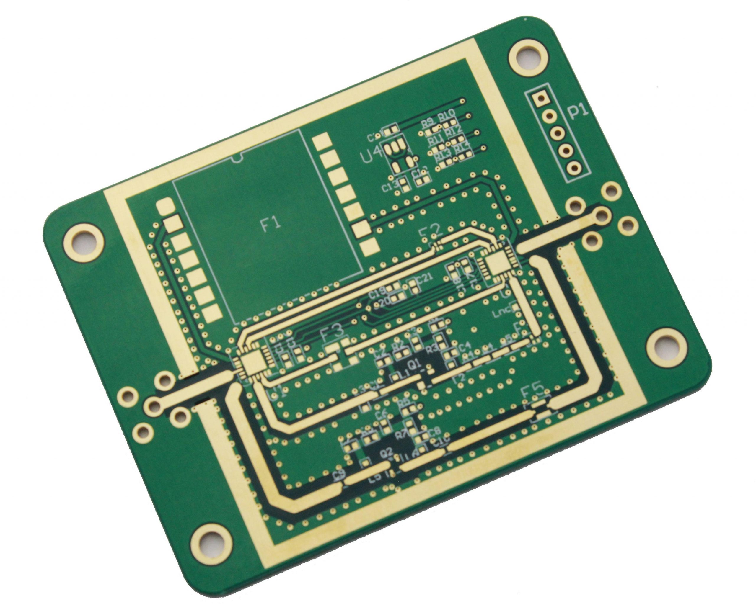
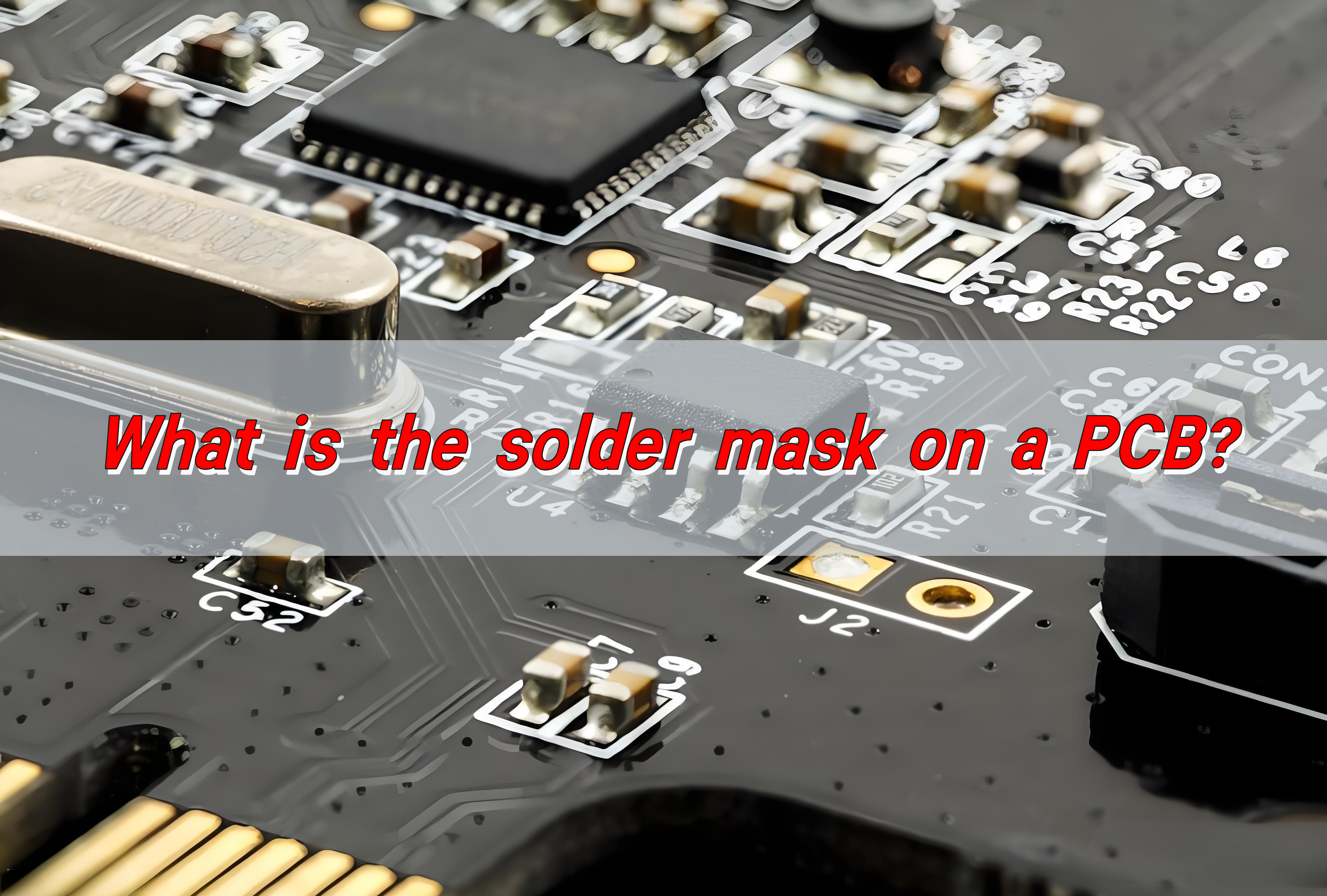
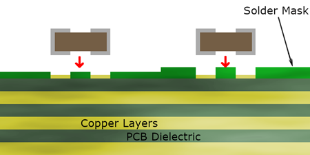
What is a solder mask? The solder mask on the PCB is a special coating covering the surface of the circuit board, usually composed of polymer resins, pigments and other materials. It is used to prevent solder from flowing into non-soldering areas during soldering, avoid short circuits, and protect copper lines from oxidation and environmental erosion.
What is solder mask layer on pcb?
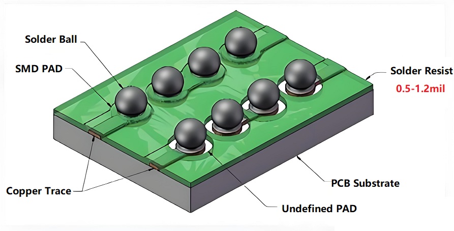
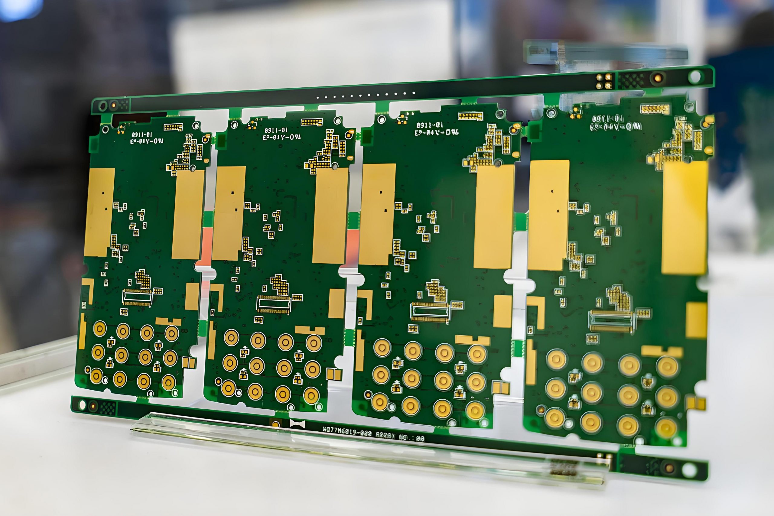
The solder mask layer is a thin polymer layer applied to the surface of a PCB to protect the copper traces from exposure to air, moisture, and solder during assembly. It is typically applied as a liquid and then cured to create a durable, insulating coating.
This layer ensures that solder only adheres to designated areas, such as component pads, while preventing unintentional connections that can cause electrical failures.
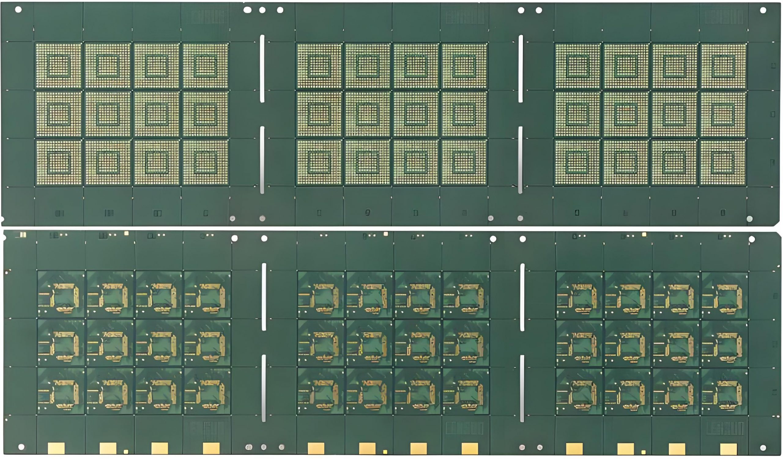
Most PCBs feature a solder mask on both sides, covering all traces except for the exposed pads where components will be soldered. The mask enhances the board’s mechanical strength, providing extra durability against physical damage.
What is a solder mask used for?
A solder mask serves multiple functions in PCB manufacturing and assembly, including:
- Prevents Solder Bridging – Stops accidental solder connections between closely spaced components.
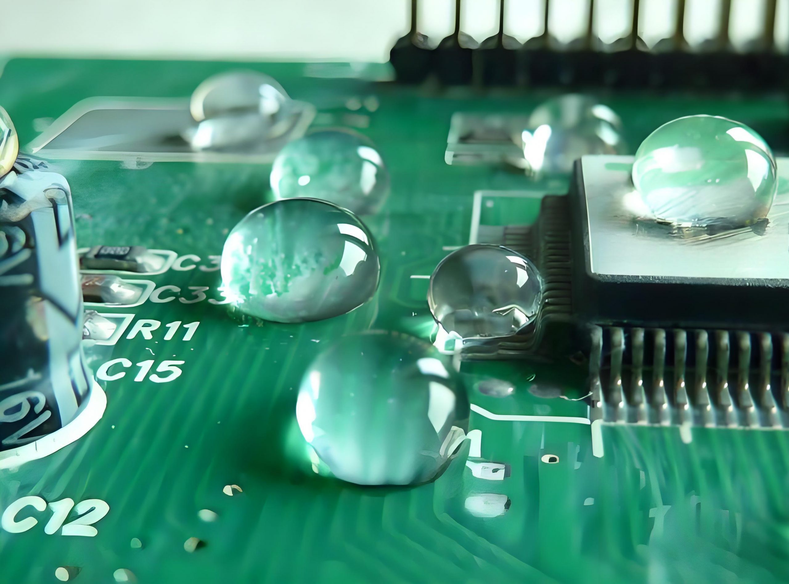
- Protects Copper Traces – Shields against oxidation and environmental damage.
- Improves Electrical Insulation – Reduces the risk of unintended electrical contact between conductive traces.
- Enhances PCB Durability – Adds a layer of mechanical strength, preventing wear and tear.
- Aesthetic Enhancement – Gives PCBs a smooth, uniform finish and a professional appearance.
By preventing shorts and increasing reliability, the solder mask plays an essential role in producing high-performance circuit boards.
What is the standard thickness of a solder mask layer?
The thickness of a solder mask depends on the manufacturing method and the type of PCB. The most common solder mask thickness values are:
- Liquid Photoimageable (LPI) Solder Mask: 0.7 to 1.5 mils (18-38 microns)
- Dry Film Solder Mask: 0.5 to 1.2 mils (12-30 microns)
- UV Curable Solder Mask: 0.2 to 1.0 mils (5-25 microns)
A well-applied solder mask ensures proper adhesion and durability without interfering with PCB functionality.
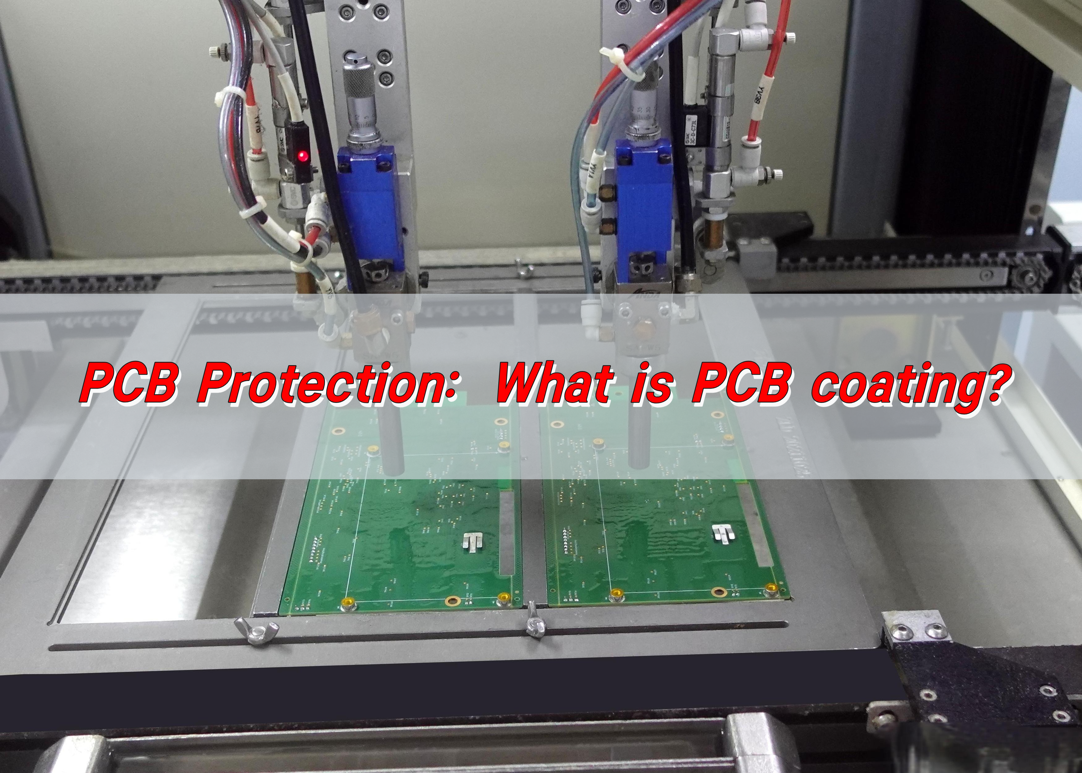
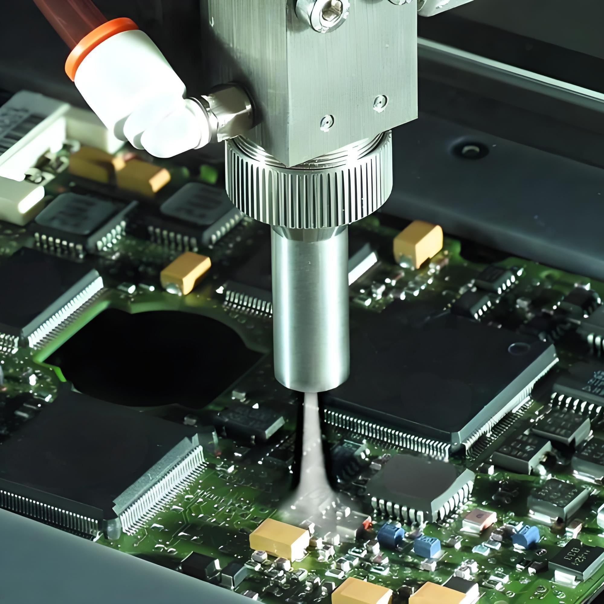
How to apply solder mask to a pcb?
The solder mask application process follows precise steps to ensure uniform coverage and proper curing:
- Surface Preparation – The PCB is cleaned to remove dust, oils, and oxidation.
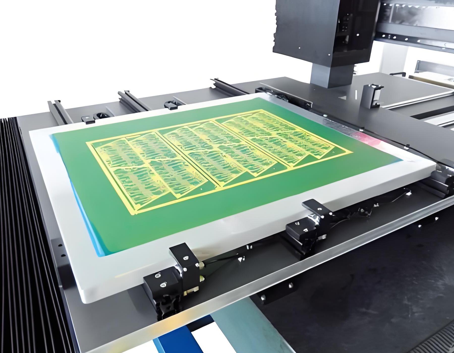
- Screen Printing – Used for simpler PCB designs.
- Curtain Coating – Ideal for high-volume production.
- Spray Coating – Suitable for complex multilayer boards.
- Pre-baking – The board is partially cured to enhance adhesion.
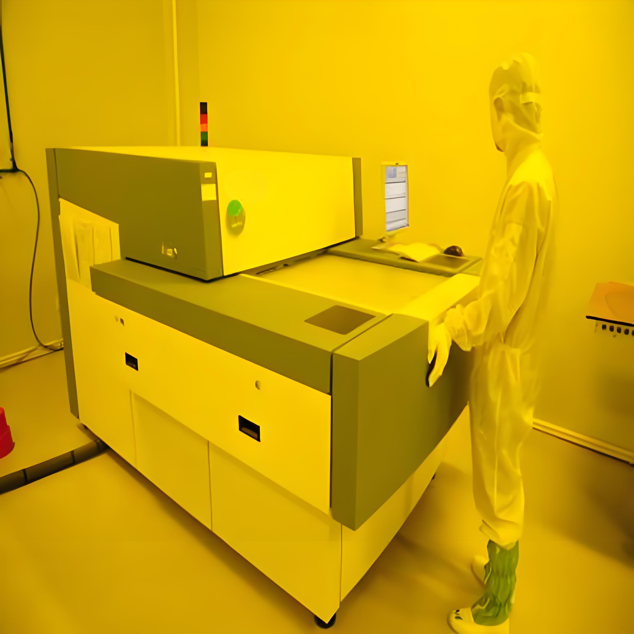
- UV Exposure – The solder mask is exposed to UV light through a photomask to define areas where it should remain.
- Development & Cleaning – Uncured mask material is removed to reveal solder pads.
- Final Curing – The PCB undergoes heat curing for maximum durability.
This process ensures a strong, long-lasting solder mask layer that can withstand harsh conditions.
How long does it take for solder mask to cure?
Curing time depends on the method used:
- UV Curing: A few minutes with high-intensity UV exposure.
- Thermal Curing: 30-60 minutes at 150°C (302°F) for enhanced durability.
- Combination Curing: UV exposure followed by thermal curing for optimal strength.
Proper curing is crucial to prevent defects like delamination, peeling, or cracking.
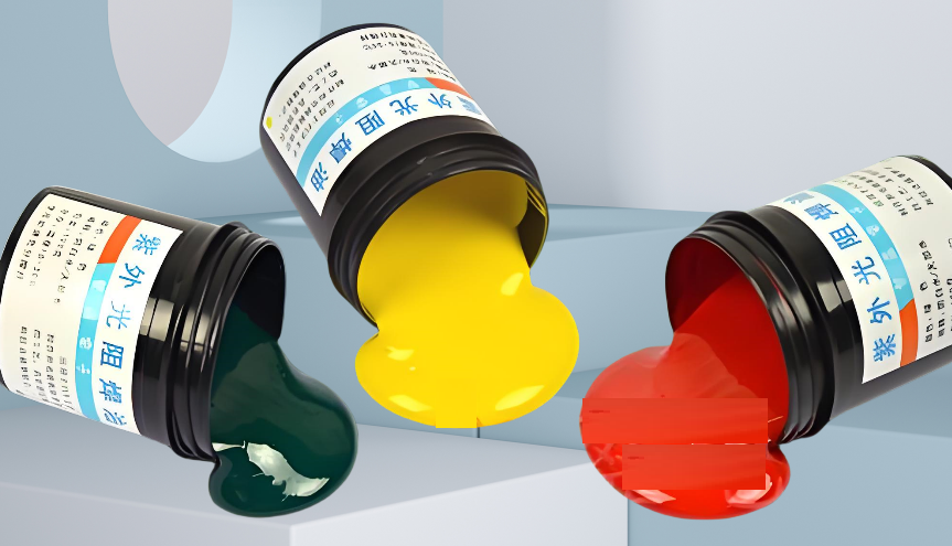
Does solder mask color matter?
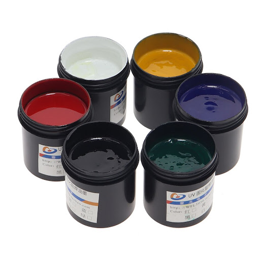
The color of a solder mask does not affect PCB performance, but it can impact visibility, aesthetics, and inspection efficiency. Common colors include:
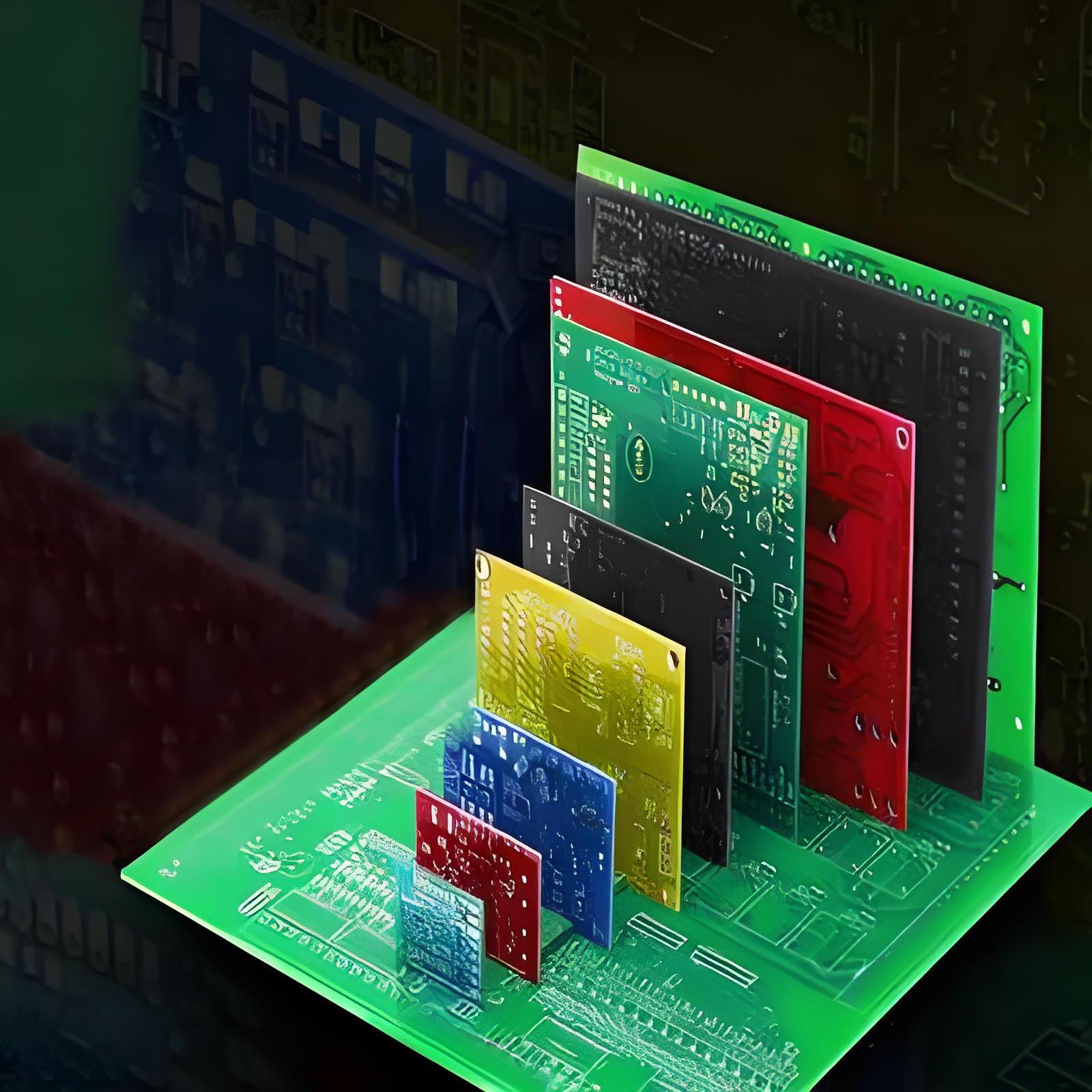
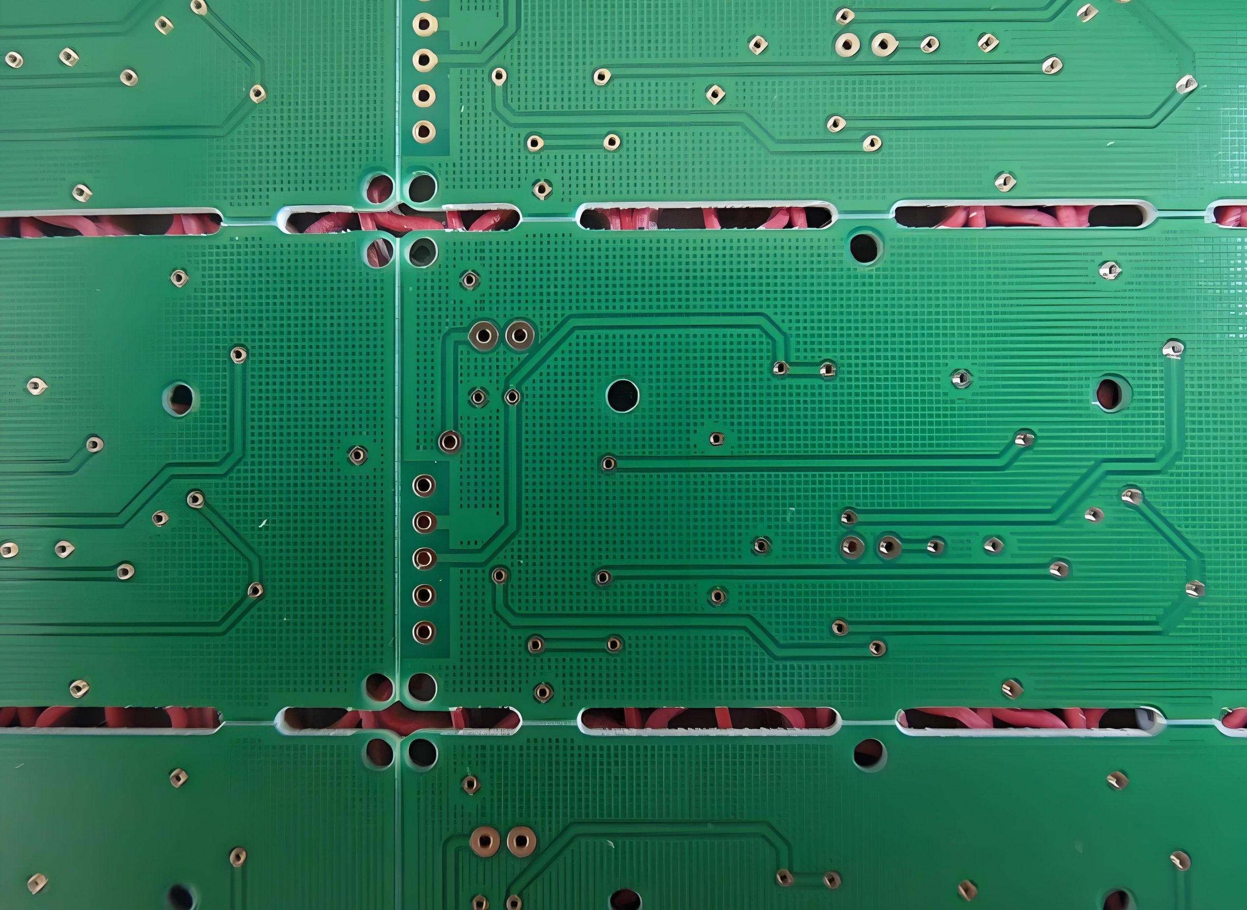
- Green – The industry standard for optimal contrast and easy inspection.
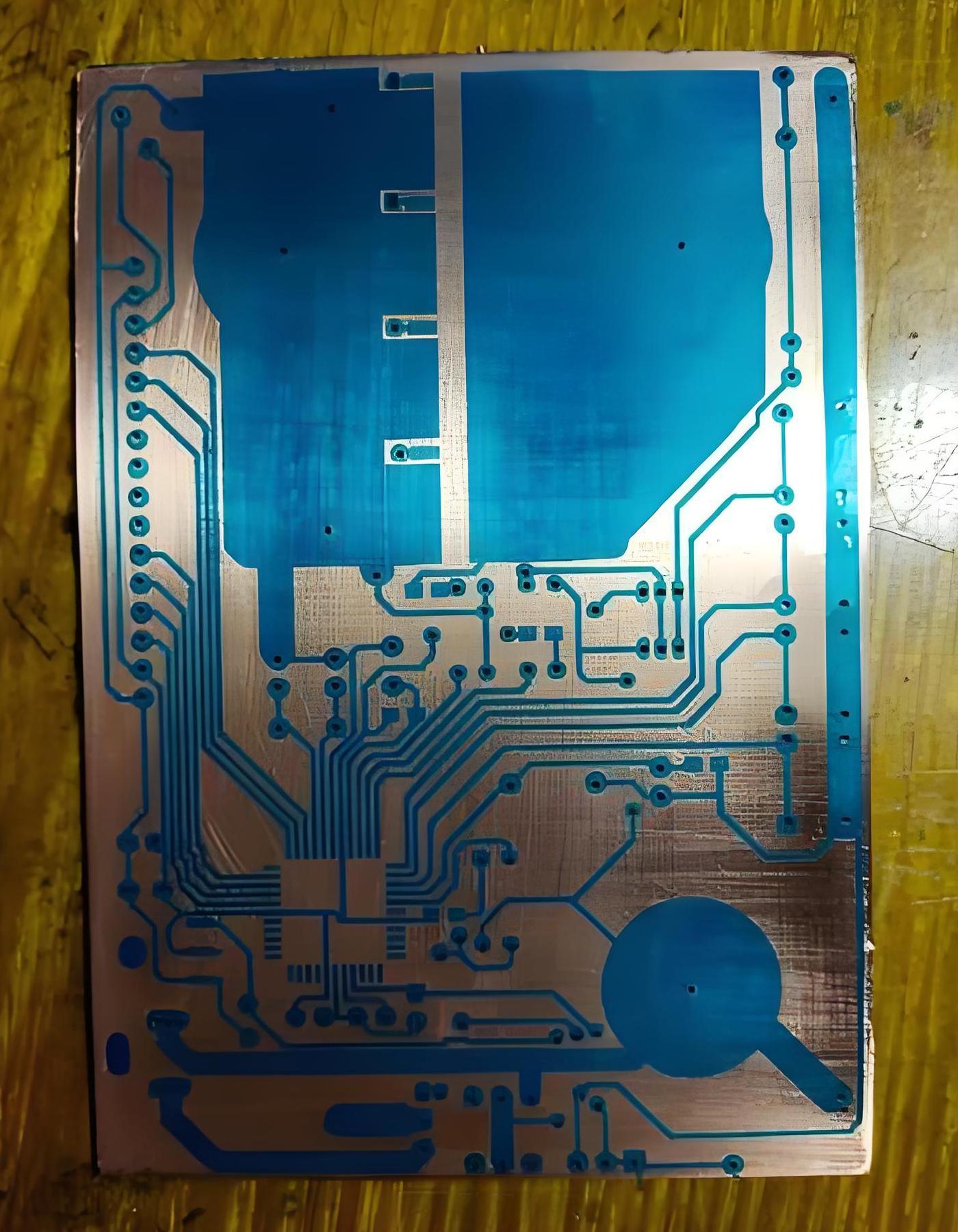
- Blue – Provides high contrast with white silkscreen text.
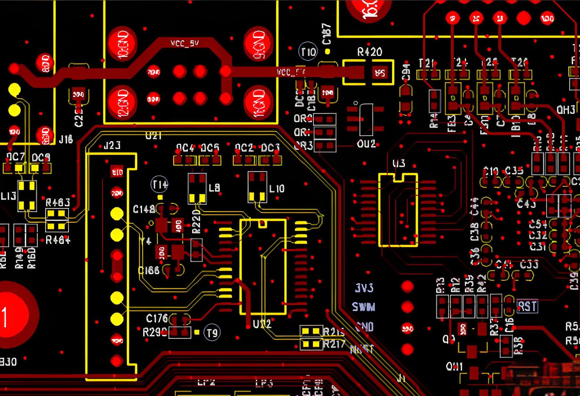
- Red – Used for high-end or custom branding.
- Black – Reduces light reflection but makes defect detection harder.
While color selection is mostly aesthetic, certain colors may aid in automated optical inspection (AOI) processes.
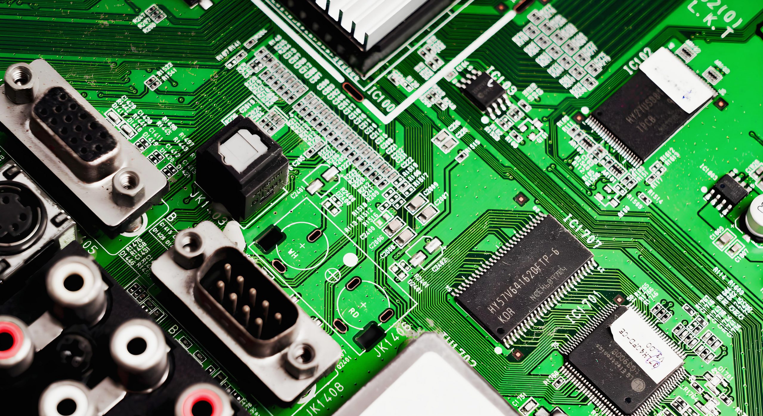
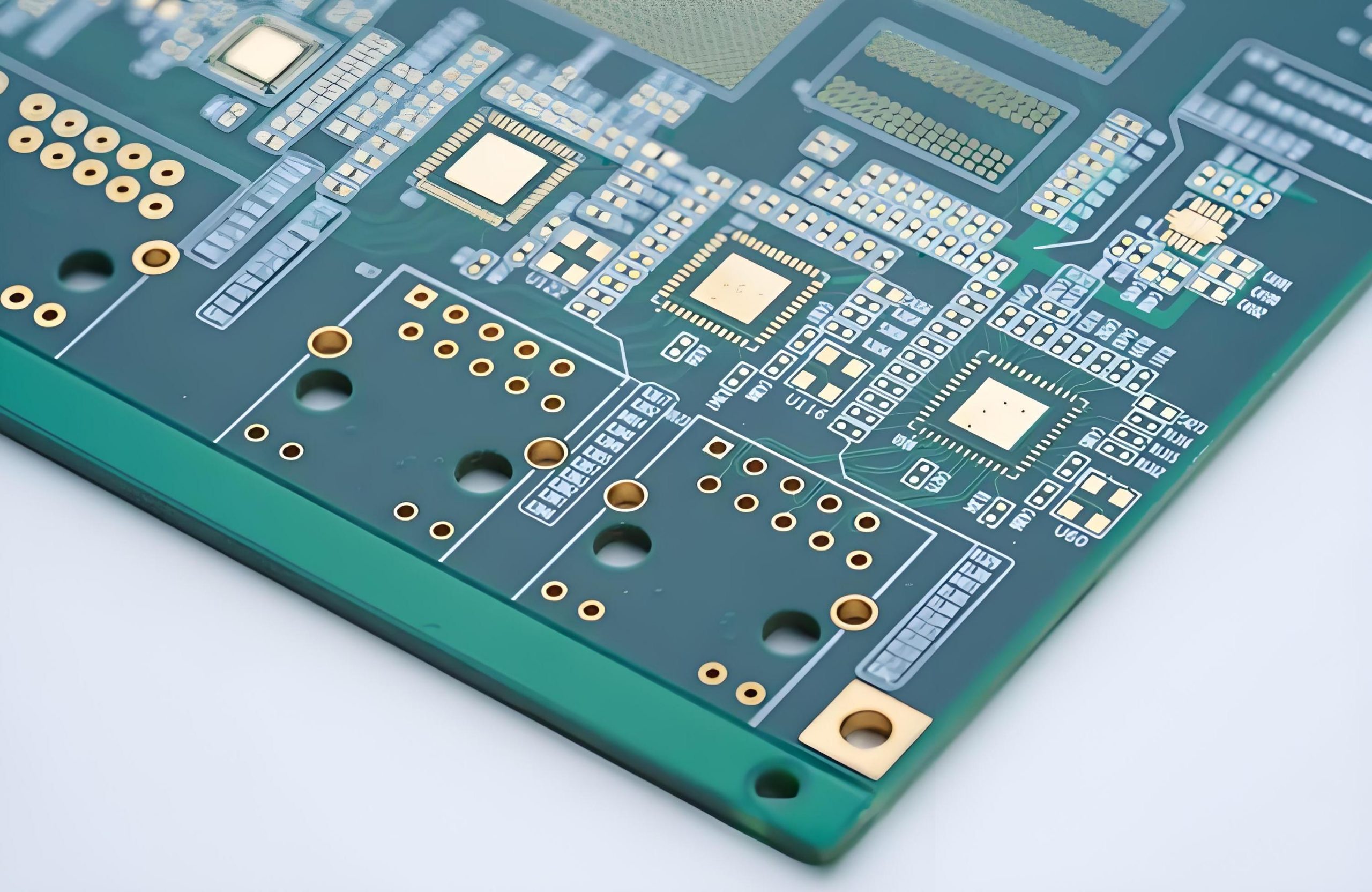
Why is most solder mask green?
Green solder mask is widely used due to:
- Best Visibility for AOI – The contrast makes defect detection easier.
- Industry Standardization – Manufacturers are optimized for green solder mask production.
- High Durability – Green solder masks tend to have better adhesion and chemical resistance.
However, manufacturers can produce PCBs with different solder mask colors based on specific project needs.
What is the difference between blue and green solder masks?
The key differences between blue and green solder masks are:
- Green – Best for automated inspection, high contrast, and industry standard.
- Blue – Vibrant appearance but slightly harder for AOI systems to detect defects.
Both options provide reliable protection, and the choice depends on aesthetic and inspection needs.
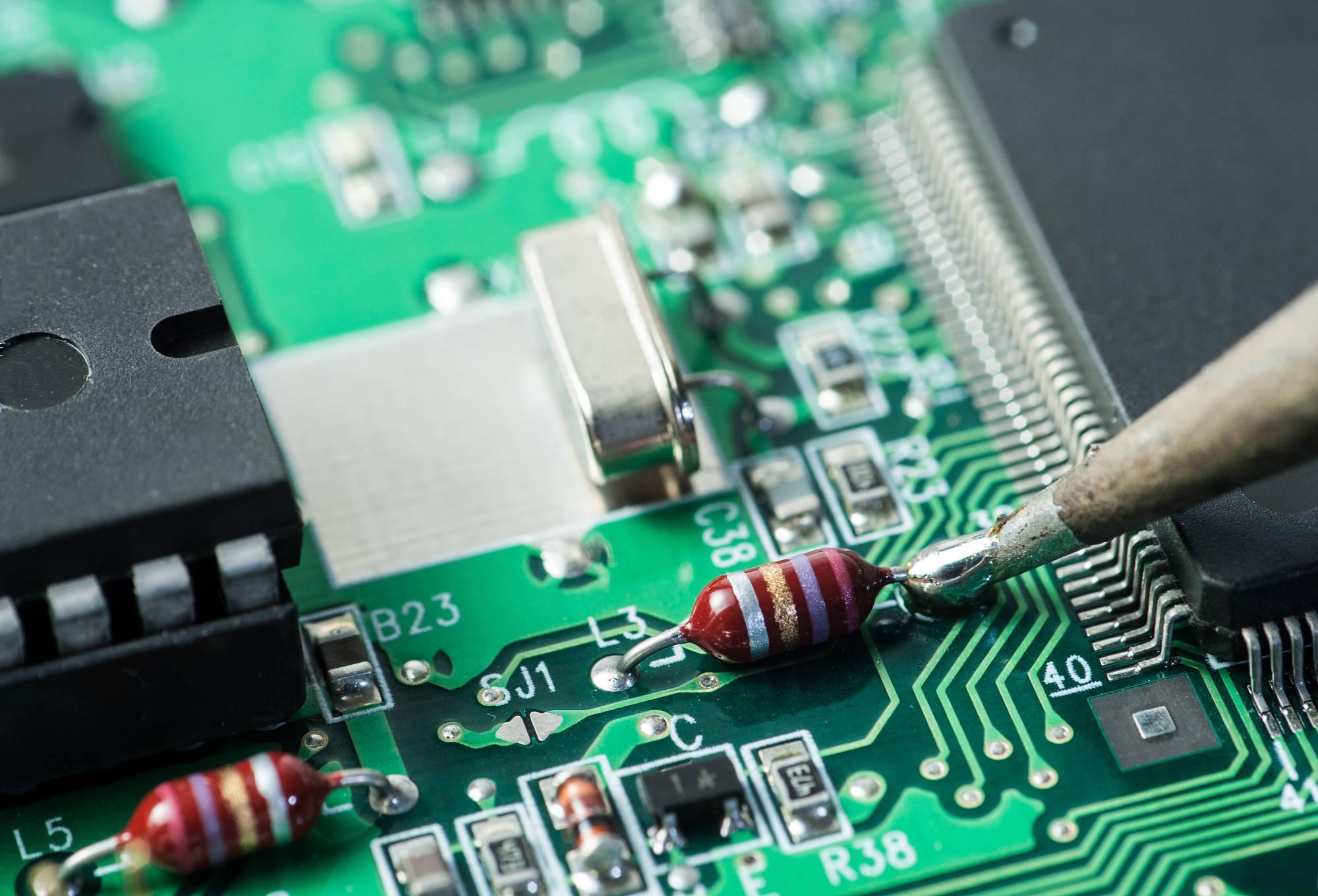
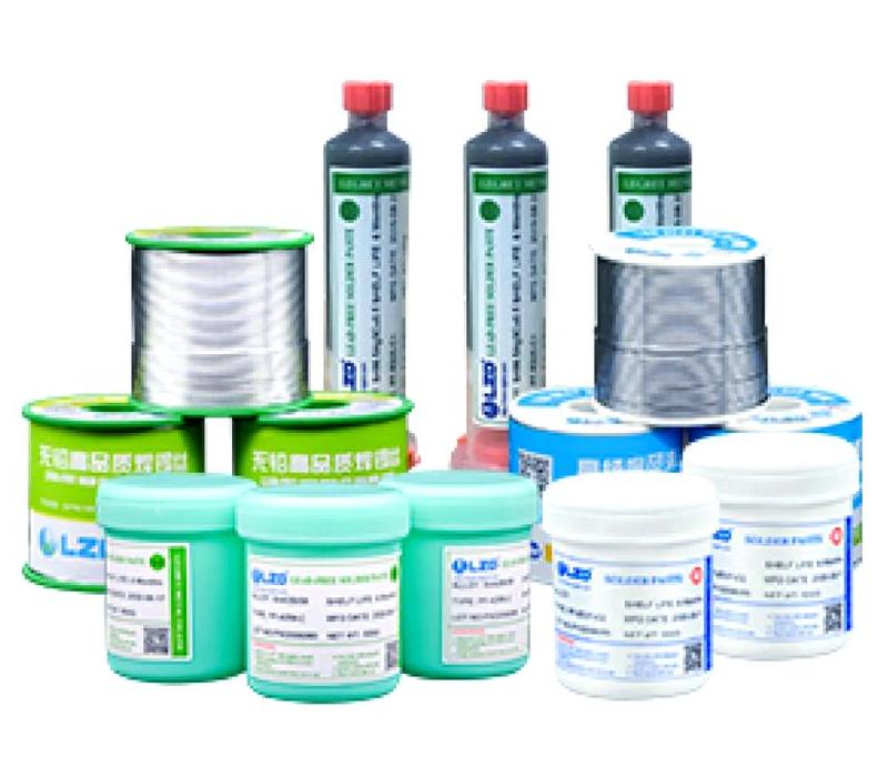
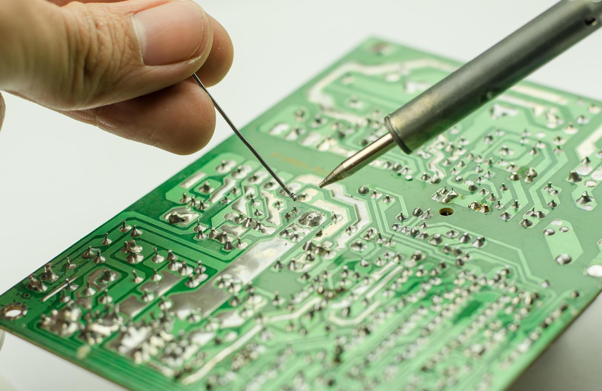
What is the difference between solder mask and solder paste?
Solder mask and solder paste serve different purposes in PCB assembly:
- Solder Mask – A permanent protective coating that prevents unintended soldering and oxidation.
- Solder Paste – A temporary material containing metal particles and flux, used to attach components before reflow soldering.
Both are essential for high-quality PCB production, but they are applied at different stages.
Conclusion:
In summary, the solder mask plays a critical role in ensuring the longevity and reliability of a PCB. It protects the copper traces, prevents soldering errors, and improves overall circuit board performance.
At EBest Circuit (Best Technology), we are committed to delivering high-quality PCBs, with precise solder mask application, to meet your specific needs. Contact us today for customized PCB solutions that will elevate your product’s performance. Email: sales@bestpcbs.com