Is RO4500 the right high-frequency laminate for your antenna PCB design? If your project requires stable impedance, low signal loss, low PIM performance, and practical PCB fabrication, RO4500 is a material family worth reviewing carefully. This guide explains RO4500 material properties, datasheet values, laminate types, antenna applications, PTFE comparison, thickness selection, and design points for reliable RF PCB production.
What Is RO4500?
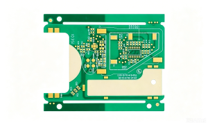
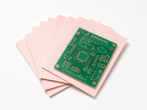
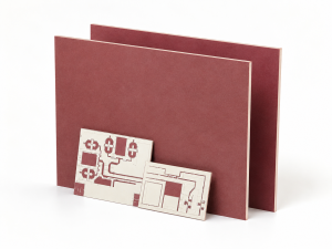
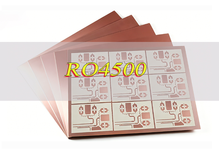
RO4500 is a high-frequency laminate series from Rogers Corporation, specifically designed for antenna PCB applications that require stable electrical performance, low insertion loss, low PIM response, and production repeatability. The RO4500 family includes three main types: RO4533, RO4534, and RO4535.
These ceramic-filled, glass-reinforced, hydrocarbon-based laminates offer controlled dielectric constant, low dissipation factor, and good passive intermodulation performance for reliable antenna circuits. For antenna PCB design, RO4500 significantly influences critical factors like impedance, wavelength, antenna size, signal loss, PIM behavior, copper selection, and final RF consistency.
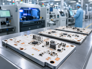
A major advantage of RO4500 is its balance of RF performance and manufacturability: unlike many traditional PTFE-based laminates, it can be easily processed using standard PCB fabrication methods and high-temperature lead-free soldering processes.
What Are the Main Types of RO4500 Laminates?
The main RO4500 laminate types are RO4533, RO4534, and RO4535. They belong to the same antenna-grade material family, but each one supports slightly different RF design needs.
- RO4533: Has the lowest Dk in the RO4500 family; suitable for antenna PCB designs that need a lower dielectric constant to support impedance control, antenna size adjustment, or specific RF signal behavior; lowest Dk option among common RO4500 laminates; suitable for antenna PCB designs requiring lower dielectric constant; helps support impedance control and antenna size adjustment; offers a low dissipation factor to reduce dielectric loss.
- RO4534: A balanced option in the RO4500 series; provides a slightly higher Dk than RO4533 while still maintaining low-loss performance and stable antenna-grade characteristics; balanced dielectric constant and RF performance; suitable for general RF communication applications; maintains low-loss antenna-grade behavior; useful when the design needs a practical middle option between RO4533 and RO4535.
- RO4535: Has the highest Dk among these three common RO4500 laminates; provides UL94 V-0 flame rating, making it suitable for antenna PCB projects where flame-retardant performance is required; highest Dk among RO4533, RO4534, and RO4535; suitable for compact antenna PCB layouts; provides UL94 V-0 flame-retardant performance; useful for applications that need both RF performance and flame rating compliance.
RO4500 High-Frequency Laminates Datasheet
The RO4500 datasheet is useful for evaluating whether the material matches a specific antenna PCB design. The most important values include dielectric constant, dissipation factor, PIM performance, thermal conductivity, Tg, flame rating, and lead-free compatibility. Below is a table and PDF for RO4500 high-frequency laminates datasheet:
| Property | RO4533 | RO4534 | RO4535 |
|---|---|---|---|
| Process Dk | 3.30 ± 0.08 | 3.40 ± 0.08 | 3.44 ± 0.08 |
| Design Dk | 3.45 | 3.55 | 3.60 |
| Df at 2.5 GHz | 0.0020 | 0.0022 | 0.0032 |
| Df at 10 GHz | 0.0025 | 0.0027 | 0.0037 |
| Typical PIM | Better than -155 dBc | Better than -155 dBc | Better than -155 dBc |
| Thermal Conductivity | 0.6 W/m·K | 0.6 W/m·K | 0.6 W/m·K |
| Tg | >280°C | >280°C | >280°C |
| Flammability Rating | Non-FR | Non-FR | UL94 V-0 |
| Lead-Free Compatible | Yes | Yes | Yes |
Rogers lists the RO4500 dielectric constant range as 3.3 to 3.5 ±0.08 and the dissipation factor range as 0.0020 to 0.0037 measured at 2.5 GHz. The datasheet also highlights low PIM response, standard PCB fabrication compatibility, good dimensional stability, and thermal performance.
Standard thickness options are also important:
- RO4533: Commonly available in 0.020 in., 0.030 in., and 0.060 in.
- RO4534: Commonly available in 0.020 in., 0.032 in., and 0.060 in.
- RO4535: Commonly available in 0.020 in., 0.030 in., and 0.060 in.
Before production, laminate availability, copper type, panel size, and tolerance requirements should be confirmed.
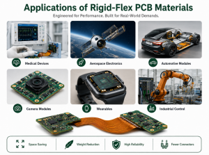
What Are Applications of Rogers RO4500?
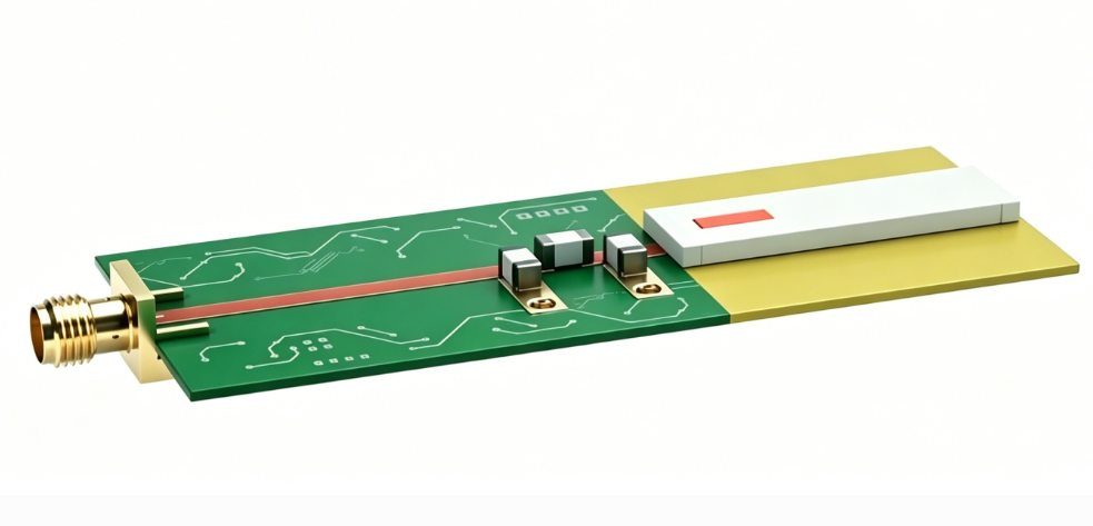
RO4500 is mainly used in antenna-related high-frequency PCB applications. It is especially suitable for wireless infrastructure and RF communication systems where material stability and production repeatability are required.
Common RO4500 applications include:
- Base station antenna PCBs
- Microstrip antenna circuits
- WiMAX antenna networks
- Wireless communication antenna systems
- RF antenna modules
- Distributed antenna systems
- Commercial antenna products
- Communication infrastructure equipment
In these applications, the PCB material must support predictable RF behavior. Antenna products often require stable impedance, controlled signal propagation, low dielectric loss, and reliable dimensional stability.
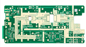
Why Is RO4500 Used for Antenna PCB Design?
RO4500 is widely adopted for antenna PCB design due to its optimal combination of antenna-grade RF performance and practical manufacturability. Specifically engineered to meet the demands of the antenna market, it offers stable electrical properties, low signal loss, and excellent low PIM performance, while being compatible with conventional PCB fabrication processes, eliminating the need for special treatment required by traditional PTFE-based laminates.
- Controlled Dk for stable RF behavior: RO4500 has a controlled Dk range (3.3 to 3.5 ±0.08), which helps maintain predictable impedance and antenna dimensions, influences how RF energy travels through the board, and improves production consistency.
- Low dissipation factor for reduced signal loss: With a dissipation factor range of 0.0020 to 0.0037 (measured at 2.5 GHz), RO4500 reduces dielectric loss, supporting better signal efficiency and overall antenna performance.
- Low PIM potential for antenna systems: RO4500 delivers excellent passive intermodulation performance (better than -155 dBc under specified conditions), which is critical for cellular infrastructure and high-power RF systems to maintain clean signal transmission.
- Superior fabrication compatibility: Unlike traditional PTFE-based laminates, RO4500 is fully compatible with conventional PCB fabrication and high-temperature lead-free soldering processes, requiring no special treatment for plated through-hole preparation, thus reducing manufacturing complexity and improving production control.
- Good mechanical and thermal reliability: It offers improved mechanical rigidity over PTFE, a Tg greater than 280°C, and thermal conductivity of 0.6 W/m·K, ensuring stability in various application environments.
How Does RO4500 Help Improve Low PIM Performance?
Passive intermodulation (PIM) is critical for antenna PCBs, as it creates unwanted signal products that degrade transmission quality, especially in high-power RF systems like cellular infrastructure. RO4500 supports excellent low PIM performance (better than -155 dBc under specified conditions) and works with fabrication and design choices to maximize PIM control. Below is how RO4500 contributes to low PIM and considerations.
- Stable material properties minimize PIM generation: RO4500’s ceramic-filled, glass-reinforced hydrocarbon composition ensures consistent dielectric properties (controlled Dk and low Df) across the laminate. This stability prevents irregularities in the material that could cause signal mixing at passive interfaces, a common source of PIM.
- Compatibility with low-PIM copper foils: RO4500 works seamlessly with low-profile, smooth copper foils which are critical for reducing PIM. Smoother copper surfaces minimize contact irregularities and signal reflections that contribute to unwanted intermodulation products, enhancing overall PIM performance.
- Robust thermal and mechanical stability: With a Tg greater than 280°C and good dimensional stability, RO4500 maintains its structure during high-temperature soldering and long-term operation. This prevents material warping or delamination, which can create loose contacts and increase PIM levels over time.
- Standard fabrication compatibility reduces PIM risks: Unlike PTFE laminates that require specialized processing, RO4500 works with conventional PCB fabrication methods. This reduces process-related inconsistencies (e.g., poor hole wall treatment, uneven plating) that often lead to higher PIM.
- Complementary design and fabrication best practices: While RO4500 provides a strong foundation for low PIM, optimal performance requires pairing it with high-quality plating, clean assembly processes, proper grounding design, and reliable RF connector soldering all of which work with RO4500’s properties to minimize PIM.
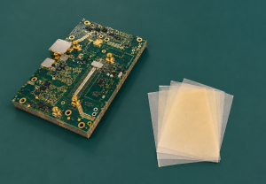
RO4500 vs PTFE Laminates: Which One Is Better for Antenna PCB?
RO4500 and PTFE laminates can both be used for antenna PCBs, but they are suitable for different project priorities.
PTFE laminates are often selected for very low-loss RF and microwave circuits. They are widely used in demanding high-frequency designs. However, PTFE materials usually require more specialized processing, which may affect cost, lead time, and manufacturing control.
RO4500 is designed to provide antenna-grade RF performance with easier PCB fabrication. It is often a better fit when the project needs low PIM potential, stable RF behavior, practical manufacturing, and cost-performance balance.
| Comparison Item | RO4500 Laminates | PTFE Laminates |
|---|---|---|
| Main Advantage | Balanced RF performance and easier fabrication | Very low loss for demanding RF designs |
| Processing | Similar to standard PCB fabrication | Often requires special processing |
| PTH Preparation | No special PTFE-style treatment required | More process-sensitive |
| Cost Control | Good for volume antenna production | Usually higher process cost |
| Mechanical Handling | More production-friendly | Softer and more sensitive |
| Typical Use | Antenna PCB, base station antenna, WiMAX | RF, microwave, radar, premium antenna systems |
RO4500 is often the better choice when manufacturability, low PIM performance, and production stability matter together. PTFE may be preferred when ultra-low loss is the top design priority.
What Should Be Considered When Designing RO4500 Antenna PCBs?
Designing antenna PCBs with RO4500 requires attention to key details that directly impact RF performance, production repeatability, and long-term reliability. These considerations cover material properties, fabrication processes, and assembly practices, ensuring the final PCB meets design requirements and application needs. Below are the critical points to keep in mind during the design process.
- Dk and Design Dk: Process Dk and design Dk are not always the same. Process Dk is mainly used for material control, while design Dk is more useful for circuit simulation. For antenna PCBs, using the correct Dk value helps improve impedance and frequency prediction.
- Copper Foil Type: Copper foil affects insertion loss, PIM behavior, and etching quality. Low-profile copper is often preferred in RF applications because smoother copper can help reduce conductor loss.
- Impedance Control: Antenna PCB traces must be controlled by line width, dielectric thickness, copper thickness, and layer structure. Even small deviations can affect RF performance, so impedance requirements should be confirmed before fabrication.
- Board Thickness and Flatness: Antenna PCBs may have larger board sizes than standard circuit boards. Flatness and dimensional stability should be reviewed carefully, especially for base station antenna boards and large RF panels.
- Via and PTH Reliability: RO4500 is easier to process than many PTFE materials, but via quality still matters. Drill quality, hole wall treatment, copper plating, and thermal stress reliability should be controlled during fabrication.
- Surface Finish: Surface finish affects solderability, contact reliability, and RF performance. ENIG, immersion silver, OSP, and other finishes may be selected depending on assembly needs and RF contact requirements.
- RF Connector Assembly: RF connector layout and soldering quality can affect impedance and PIM performance. Connector footprints, ground via placement, solder joints, and mechanical support should be reviewed before production.
- Fabrication Capability: The PCB manufacturer should understand Rogers laminate handling, controlled impedance, RF trace accuracy, low PIM requirements, and inspection control. A proper DFM review before production can help reduce avoidable revisions.
FAQs About RO4500 High-Frequency Laminates
Q1: What is the difference between RO4500 and FR-4 laminates for antenna PCBs?
A1: The core difference lies in RF performance and application scenarios. FR-4 is a standard PCB material with higher dielectric loss (Df) and unstable dielectric constant (Dk) at high frequencies, making it unsuitable for high-frequency antenna designs. RO4500 is a high-frequency laminate specifically engineered for antennas, with controlled Dk (3.3-3.5 ±0.08), low Df (0.0020-0.0037 at 2.5 GHz), and low PIM performance, while also being compatible with conventional FR-4 fabrication processes.
Q2: What is the maximum operating temperature of RO4500 laminates?
A2: RO4500 has a glass transition temperature (Tg) greater than 280°C, which means it can maintain stable mechanical and electrical properties in high-temperature environments. Its maximum continuous operating temperature is typically around 150°C, and it can withstand the high temperatures of lead-free soldering processes (up to 260°C for short durations), making it suitable for harsh industrial and communication infrastructure applications.
Q3: Does RO4500 require special storage conditions?
A3:Yes, RO4500 laminates need proper storage to maintain their performance. They should be stored in a clean, dry environment with relative humidity between 30%-60% and temperature between 15°C-30°C, avoiding direct sunlight, moisture, and chemical contamination. Unopened laminates have a shelf life of 6-12 months; once opened, they should be used within 30 days to prevent moisture absorption affecting dielectric properties.
Q4: Can RO4500 be used for 5G base station antenna PCBs?
A4: Absolutely. RO4500 is widely used in 5G base station antenna PCBs due to its excellent high-frequency performance. Its controlled Dk ensures stable impedance and signal propagation at 5G frequency bands (sub-6GHz and mmWave), low Df reduces signal loss, and low PIM performance (better than -155 dBc) prevents signal interference, which is critical for 5G communication quality.
Q5: What is the moisture absorption rate of RO4500 laminates?
A5: RO4500 has extremely low moisture absorption, typically less than 0.04% (per IPC-TM-650 2.6.2.1 standard). This low moisture absorption ensures that its dielectric properties (Dk and Df) remain stable even in humid environments, avoiding signal degradation and improving the long-term reliability of antenna PCBs.
Q6: Is RO4500 compatible with lead-free soldering processes?
A6: Yes, RO4500 is fully compatible with high-temperature lead-free soldering processes. Unlike traditional PTFE laminates that require special treatment, RO4500 can withstand the 260°C soldering temperature required for lead-free soldering without warping, delamination, or damage to its electrical properties, reducing manufacturing complexity.
Q7: What is the typical cost difference between RO4500 and PTFE laminates?
A7: RO4500 is more cost-effective than PTFE laminates. On average, RO4500 costs 30%-50% less than PTFE laminates for the same thickness and copper weight. This is because RO4500 is compatible with conventional PCB fabrication processes, eliminating the special processing costs required for PTFE, making it more suitable for volume production of antenna PCBs.
Conclusion
In summary, RO4500 stands out as a reliable, cost-effective high-frequency laminate solution for antenna PCB design, balancing excellent RF performance, including stable dielectric properties, low loss, and low PIM with easy manufacturability, making it an ideal choice for wireless infrastructure and various antenna-related applications when paired with thoughtful material selection and design considerations.