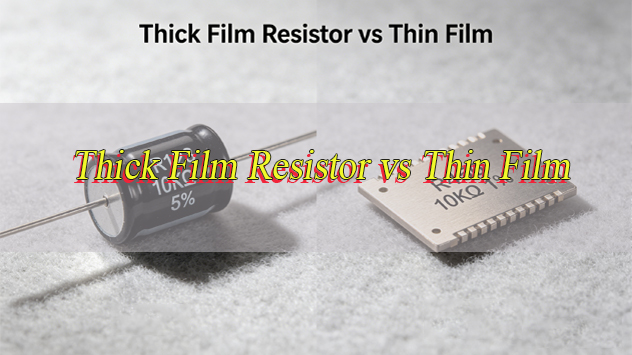
When designing RF circuits for communication devices, radar systems or microwave equipment, how do you choose between thick film resistor vs thin film to avoid signal degradation, high costs and performance failures? This common challenge plagues engineers, as the wrong choice can compromise high frequency stability, increase insertion loss and reduce long-term reliability.
Understanding their differences, advantages and ideal use cases is essential to optimizing circuit design and ensuring your RF systems perform as intended. This guide breaks down their basic construction, performance characteristics and application suitability to help you make an informed decision tailored to your RF needs.
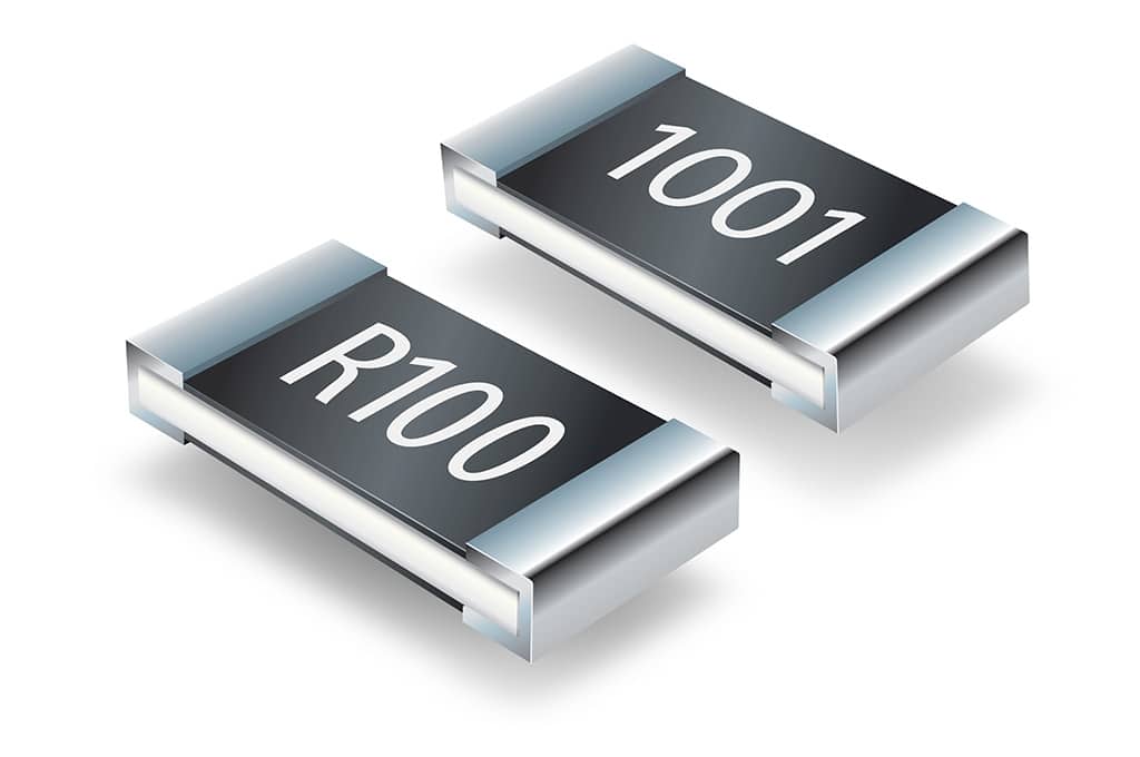
What Are Thin Film Resistors?
Thin film resistors are precision electronic components made by depositing a 50 to 250 nanometer thin layer of resistive material, typically nickel chromium (NiCr) or tantalum nitride (TaN), onto a ceramic substrate via physical vapor deposition (PVD) or vacuum sputtering.
This ultra-thin, uniform layer is etched or laser trimmed forprecise resistance values, making them ideal for RF circuits requiringaccuracy and stability. Thin film resistors are a go-to for projects where even a small resistance drift can disrupt the entire signal chain and derail prototype testing.
Key Performance Advantages of Thin Film Resistors:
- Smooth, defect-free surface with consistent material properties from precision manufacturing
- Low temperature coefficient of resistance (TCR: ±1 to ±25 ppm/°C), ensuring stable performance across temperature changes
- Low electrical noise and minimal parasitic inductance/capacitance, critical for signal integrity
- Tight tolerance down to ±0.01%, ideal for precision RF circuits
Ideal Applications for Thin Film Resistors:
- High frequency RF circuits where signal integrity is non-negotiable
- Precision RF components: signal amplifiers, filters and impedance matching networks
- Microwave communication modules and high speed data transmission circuits
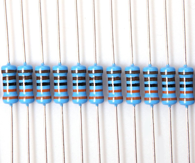
What Are Thick Film Resistors?
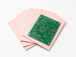
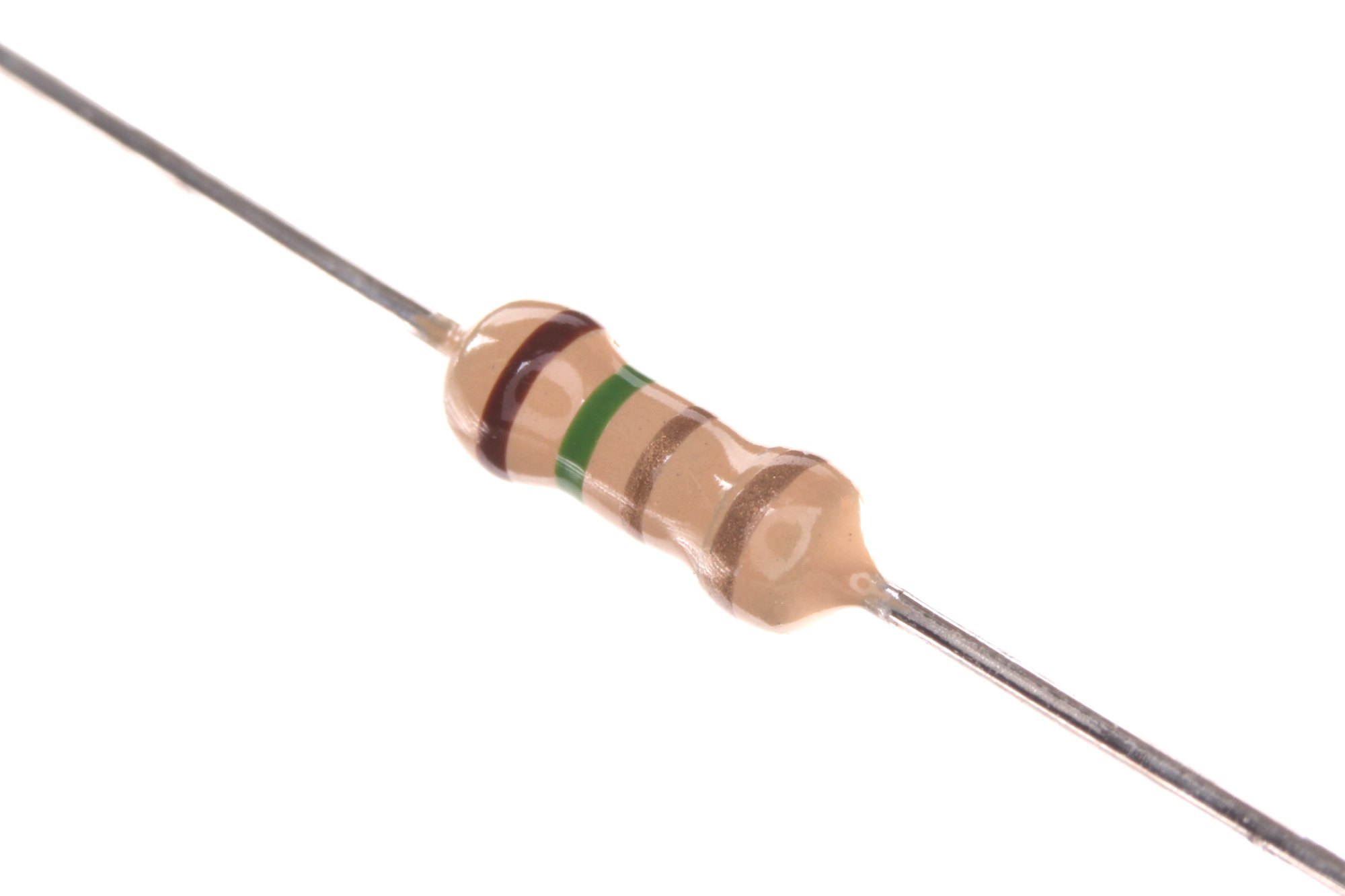
Thick film resistors arecost effective components produced by screen printing viscous resistive paste onto a ceramic substrate, followed by high temperature firing (850°C to 900°C). The paste, made of metal oxides (e.g., ruthenium dioxide RuO2), glass frit and organic binders, forms a 10 to 100 micrometer film that is significantly thicker than thin film variants.
This simple, scalable process makes them ideal for high volume applications. For mass-produced consumer RF devices, they’re often the most practical choice due to theirlower cost and consistent performance in less demanding environments.
Key Performance Traits of Thick Film Resistors:
- Granular, sponge-like structure from sintering, leading to higher TCR (±100 to ±200 ppm/°C)
- Higher electrical noise and greater parasitic capacitance compared to thin film variants
- Superior power handling capability (up to several watts)
- Strong resistance to environmental stress: humidity, mechanical shock and harsh conditions
Ideal Applications for Thick Film Resistors:
- Cost-sensitive, high-volume RF products: consumer electronics and IoT devices
- High power RF circuits: power amplifiers and transmitters
- Harsh environment use: industrial RF sensors and automotive RF systems
What Is The Difference Between Thick and Thin Film Resistors?
Core differences between thick film resistors vs thin film stem from their manufacturing processes, which impact electrical performance, physical properties and RF suitability. Below is a detailed comparison of parameters critical for RF component selection.
| Parameter | Thick Film Resistors | Thin Film Resistors |
| Manufacturing Process | Screen printing of resistive paste onto ceramic substrate followed by high temperature firing 850°C 900°C | Vacuum sputtering PVD of thin resistive metal alloy layer onto ceramic substrate followed by laser trimming |
| Film Thickness | 10 100 micrometers | 50 250 nanometers |
| Resistive Material | Metal oxides e g RuO2 mixed with glass frit | Metal alloys e g NiCr TaN |
| Tolerance | ±1% to ±5% typical | ±0 01% to ±1% typical |
| TCR ppm/°C | ±100 to ±200 | ±1 to ±25 |
| Electrical Noise | Higher 1/f noise due to granular structure | Very low noise due to uniform film structure |
| Parasitic Inductance/Capacitance | Higher due to thicker film and screen printed structure | Very low ideal for high frequency applications |
| Power Handling | Higher up to several watts | Lower typically 0 05W to 0 25W for standard sizes |
| Cost | Lower ideal for high volume production | Higher due to precision manufacturing process |
| High Frequency Stability | Poorer resistance drifts at GHz frequencies | Excellent stable resistance up to 20 GHz and beyond |
| RF Insertion Loss | Higher especially at frequencies above 10 GHz | Lower within 0 5 dB up to 20 GHz |
When To Use Thick Film Resistors Over Thin Film?
Choose thick film resistors if your RF project meets these criteria:
- Cost, power handling and environmental robustness are higher priorities than precision and high frequency stability, with minor resistance drifts not affecting performance.
- Circuits operate below 10 GHz and do not require tight tolerance or minimal signal loss.
- High-volume, cost-sensitive products (e.g., consumer electronics, IoT devices), where reducing per-unit cost improves competitiveness.
- Applications involve harsh environments (high humidity, mechanical vibration, extreme temperatures) like industrial RF sensors, automotive RF systems.
- RF circuits require high power handling (exceeding 0.5W) (e.g., power amplifiers, transmitters), where thick film resistors’ superior heat dissipation prevents burnout.
- Assembly uses reflow/wave soldering, with thick film resistors compatible with automated mounting and lower assembly costs.
- Components must comply with environmental standards (e.g., RoHS) with stable long-term performance at low cost.
- RF circuits are for non-precision scenarios (e.g., basic signal detection), where higher noise/parasitics do not affect signal quality.
- Miniaturized RF devices need small, lightweight resistors with thick film’s miniaturized packaging.
Thick film resistors balance performance and cost for IoT and consumer RF products. They outperform thin film in outdoor/factory environments, are compatible with automated assembly (ideal for high-volume production), and offer robust structure + RoHS compliance for automotive/industrial use at low cost.
When To Use Thin Film Resistors Over Thick Film?
Choose thin film resistors if your RF project meets these criteria:
- Precision, high frequency stability, low noise and minimal insertion loss are critical (minor signal degradation causes product failure).
- Circuits operate above 10 GHz (e.g., radar, microwave, satellite communication), where thick film’s poor stability causes drift/distortion.
- Tight tolerance (±1% or better) and low TCR (±1 to ±25 ppm/°C) are required for variable-temperature environments (e.g., aerospace, outdoor precision instruments).
- Minimal parasitic inductance/capacitance is needed (e.g., high-speed data transmission, microwave ICs) to avoid impedance disruption.
- RF products require long-term electrical stability (5+ years) (e.g., medical, aerospace devices), where thin film’s uniform structure ensures consistency.
- Low electrical noise is non-negotiable (e.g., LNAs, RF receivers) to prevent weak signal interference.
- Miniaturized RF devices need small, high-precision resistors (e.g., 0201/0402 sizes) without performance loss.
- High-precision impedance matching networks require minimal resistance deviations to avoid signal loss/power inefficiency.
- Resistors must comply with strict industry standards (aerospace, medical, defense) for precision/reliability.
- RF circuits are part of high-end systems (military radar, communication satellites), where failure costs outweigh thin film’s higher initial cost.
- High-speed RF data transmission (5G/6G base stations) needs minimal insertion loss/low parasitics for high data rates.
- Wide resistance range (1 ohm to 3 Mohm) with high precision, a thin film strength from vacuum sputtering.
Thin film resistors are essential for high-frequency radar signal integrity. Their higher cost is justified by reliable performance, critical for aerospace, medical and defense industries (failure risks costly/dangerous outcomes). For precision medical RF instruments, 5G base stations, they deliver low noise, tight tolerance and long-term stability (improves performance, reduces field failures) and meet strict industry standards for regulated applications.
Why Do Thick Film Resistors Have Worse High-Frequency Stability than Thin Film in RF Circuits?
Core Reason for Poor High-Frequency Stability in Thick Film Resistors:
Thick film resistors have poorer high frequency stability than thin film variants due to their physical structure and manufacturing process. Their granular, sponge-like structure (from sintering) causes inconsistent material properties and higher parasitic capacitance, leading to resistance drift above 10 GHz.
Additional Contributing Factors:
- Random inclusions and micro cracks (after laser trimming) absorb gases/moisture, worsening stability
- Thicker film increases electron travel distance, causing slower response times and phase shifts at high frequencies
Thin film resistors’ ultra-thin, uniform layers and low parasitics maintain stable resistance up to 20 GHz+, making them more reliable for high-frequency RF use and the preferred choice for GHz-range projects.
Which Has Lower Insertion Loss: Thick Film Resistor vs Thin Film in RF Applications?
Thin film resistors have lower insertion loss than thick film resistors in RF applications, especially above 10 GHz.
Insertion loss (signal power lost through the resistor) is minimized by thin film resistors’ low parasitic inductance, capacitance and uniform structure. This difference is noticeable above 10 GHz.
Insertion Loss Comparison by Frequency:
- Lower frequencies: Both types have similar insertion loss (within 0.25 dB)
- Above 10 GHz: Thick film resistors’ insertion loss rises significantly (≥0.5 dB at 20 GHz)
Thin film resistors’ planar structure and minimal parasitics keep insertion loss low, suiting RF circuits where signal integrity is critical (microwave filters, attenuators, power dividers)—even 0.1 dB difference impacts performance.
Do Thick Film Resistor vs Thin Film Differ in Reliability Under RF High-Power Conditions?
Yes, thick film resistors vs thin film differ significantly in high power RF reliability. Thick film resistors are more reliable due to higher power handling and robust structure.
Why Thick Film Resistors Excel in High-Power RF Conditions:
- Thicker film layer dissipates heat more effectively (handles up to several watts)
- Glass frit in paste provides better thermal stability and resistance to thermal shock
Limitations of Thin Film Resistors in High-Power Settings:
- Lower power ratings (0.05W to 0.25W for standard sizes)
- Prone to burnout under excessive power
- Reliable only in low to moderate power RF circuits
Thin film resistors can fail prematurely in high-power setups, so matching resistor type to power requirements is critical for RF circuit reliability.
Thick Film Resistor vs Thin Film: Which One Is Better for RF Applications?
The better choice depends on RF circuit specific requirements, no one-size-fits-all solution. Priorities include frequency, power, cost and environment.
Choose Thin Film Resistors For:
- Circuits operating above 10 GHz (radar, microwave, satellite, 5G/6G high-frequency components).
- Precision needs: tight tolerance (±0.01%), low noise, minimal insertion loss, low TCR (±1 to ±25 ppm/°C).
- Key applications: radar, microwave modules, LNAs, precision RF filters, impedance matching, high-speed data transmission.
- High-stakes industries: aerospace, defense, medical, industrial precision measurement (long-term reliability, strict standards).
- Miniaturized RF devices (portable precision instruments, compact microwave modules) needing small, high-precision components.
- Long-term stability (5+ years) (medical RF devices, aerospace communication systems).
Choose Thick Film Resistors For:
- Circuits operating below 10 GHz
- Priorities: cost savings and high power handling
- Key applications: consumer electronics, industrial RF equipment, high power transmitters
Aligning their differences with a circuit’s performance needs ensures optimized performance, lower costs and long-term reliability. Matching resistor type to application requirements saves time, money and frustration in RF design/testing.