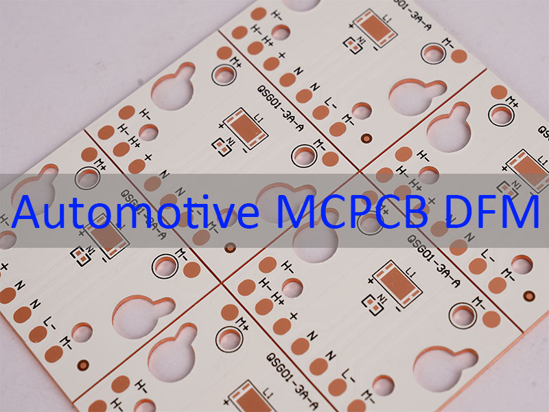
Automotive MCPCB DFM (Design for Manufacturability for automotive metal-core printed circuit boards) refers to the systematic optimization of board design to align with manufacturing capabilities, ensuring higher reliability and yield in demanding automotive applications. This article explores how strategic DFM practices address common challenges in automotive MCPCB production while boosting performance and consistency.
Pain Points in Automotive MCPCB Assembly
- Overlooked thermal expansion mismatches causing delamination or solder joint failure.
- Non-compliant tolerances leading to misalignment during SMT placement.
- Poor stack-up design resulting in signal integrity issues or excessive heat buildup.
- Incompatible material choices that fail automotive temperature or vibration standards.
- Lack of DFM expertise causing costly rework and delayed time-to-market.
To tackle these challenges, partnering with an experienced MCPCB manufacturer that integrates DFM into every design phase is critical. Here’s how Best Technology addresses them:
- Match material CTE (coefficient of thermal expansion) to copper core for reduced thermal stress.
- Adhere to strict tolerance rules (e.g., PTH ±4mil, NPTH ±2mil) for precise SMT alignment.
- Optimize stack-up with appropriate dielectric thickness for balanced thermal and electrical performance.
- Use automotive-grade substrates (aluminum/copper core) compliant with IATF 16949 standards.
- Provide early DFM feedback to eliminate design flaws before production starts.
With 20 years of expertise in PCB and MCPCB manufacturing, EBest Circuit (Best Technology) specializes in high-reliability automotive MCPCB solutions. We hold IATF 16949:2016 certification—critical for automotive applications—and maintain a 97% on-time delivery rate. Our 1,600+ sqm monthly MCPCB capacity, combined with in-house component sourcing (from authorized distributors like Digikey and Mouser) and advanced assembly equipment (Yamaha YSM20R SMT mounters, X-ray inspection systems), ensures consistent quality and yield. Pls feel free to contact us at sales@bestpcbs.com for DFM support tailored to your automotive project.
What Is Automotive MCPCB DFM?
Automotive MCPCB DFM refers to the practice of designing a metal core printed circuit board for automotive use with manufacturing in mind from the beginning. It is not only about making the board function properly, but also about making sure it can be produced with stable quality, good yield, and reasonable cost.
It usually covers these aspects:
- Thermal performance
The board must transfer and spread heat efficiently, especially in automotive lighting, power control, and high-load electronic systems. - Material compatibility
The aluminum base, copper circuit layer, and dielectric material must work well together during fabrication and long-term use. - Manufacturing limits
Trace width, spacing, hole size, board thickness, and tolerance must all stay within practical production capability. - Reliability in harsh environments
Automotive MCPCBs often operate under vibration, humidity, thermal cycling, and wide temperature ranges such as -40°C to 125°C or higher. - Process stability
A good DFM design helps avoid lamination issues, soldering defects, warpage, dielectric cracking, and other production risks.
Compared with standard PCB DFM, automotive MCPCB DFM pays much closer attention to heat dissipation, structural durability, and long-term reliability. This is because vehicle electronics are exposed to far more demanding service conditions than many consumer products.
When engineers apply DFM early, they can reduce redesign cycles, improve manufacturability, raise production yield, and build a board that is better suited for automotive-grade applications.
What Materials Are Best for Automotive MCPCB DFM Design?
Choosing the right material is foundational to DFM success.
Below are top choices aligned with automotive needs:
| Material Type | Substrate | Key Properties | Automotive Use Case |
|---|---|---|---|
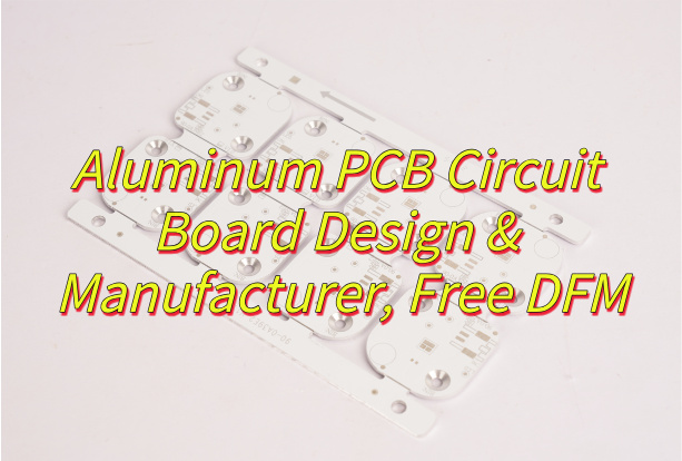
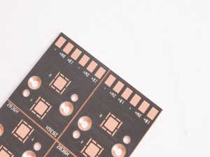
| Aluminum Core MCPCB | Aluminum (1-10L) | Lightweight, high thermal conductivity (1-3 W/mK) | LED headlights, power modules |
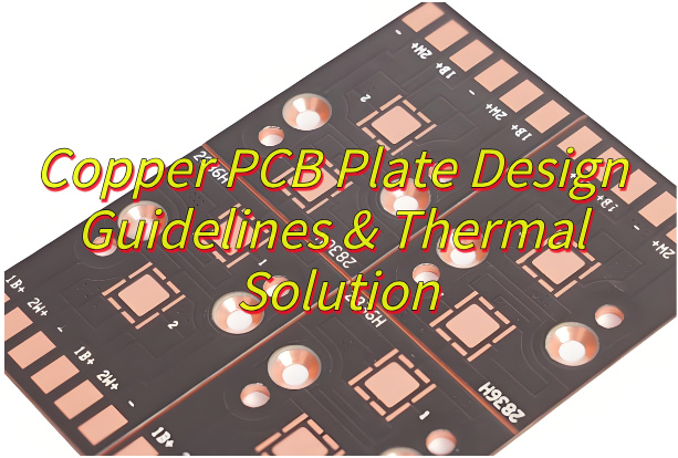
| Copper Core MCPCB | Copper (1-10L) | Higher thermal conductivity (3-5 W/mK), durable | Engine control units (ECUs) |
| SinkPAD MCPCB | Copper + Aluminum | Enhanced heat dissipation via embedded pads | High-power inverters |
All materials comply with RoHS and REACH standards, ensuring environmental safety.
How Does Thermal Management Impact Automotive MCPCB Manufacturability?
Thermal management is the #1 driver of MCPCB DFM. Poor thermal design leads to:
- Solder joint fatigue from repeated heating/cooling cycles.
- Delamination between copper core and dielectric layers.
- Reduced component lifespan (e.g., LEDs failing prematurely).
DFM strategies to optimize thermal performance include:
- Using thicker copper cores (up to 10oz) for better heat spreading.
- Designing thermal vias (0.59mil wall thickness for normal PTH) to transfer heat to the core.
- Maintaining minimum line width/space (4/4mil) to avoid overheating during operation.
These steps directly improve yield by reducing thermal-related defects during assembly and field use.
What Are the Key Stack-Up Considerations in Automotive MCPCB Design?
Stack-up design balances electrical, thermal, and mechanical needs. Critical DFM rules include:
- Dielectric Thickness: Keep between 0.5oz–10oz conductor thickness to prevent warpage.
- Layer Count: 1-10L for MCPCB (optimal for automotive power applications).
- Via Type: Use blind/buried vias (max aspect ratio 10:1) to save space and improve signal integrity.
- Copper Distribution: Uniform copper pour to avoid thermal hotspots.
A well-designed stack-up reduces assembly errors (e.g., misaligned layers) and boosts reliability under vibration.
How Do Automotive Standards Affect MCPCB DFM Requirements?
Automotive standards (IATF 16949, ISO 16750) dictate strict DFM rules:
- Tolerance Compliance: PTH ±4mil, NPTH ±2mil to ensure fit with connectors.
- Material Certification: Only use substrates (e.g., aluminum, copper) tested for -40°C to 125°C operation.
- Testing Requirements: Mandatory AOI, X-ray, and functional testing to catch defects pre-shipment.
Adhering to these standards avoids recalls and ensures compliance with OEM requirements.
What Tolerances and Design Rules Should Be Followed in Automotive MCPCB?
Strict tolerances are non-negotiable for automotive MCPCB DFM.
Key rules:
| Parameter | Tolerance |
|---|---|
| PTH Diameter | ±4mil |
| NPTH Diameter | ±2mil |
| Outline (Laser) | +0.20/-0.05mm |
| Min Line Width/Space | 4/4mil |
| Min Hole Spacing (PTH) | 20mil |
Following these rules ensures SMT placement accuracy (Yamaha YSM20R supports 0.25mm BGA pitch) and reduces rework.
How To Optimize Automotive MCPCB For Manufacturability?
Optimization starts with early DFM collaboration.
Steps include:
- DFA Checks: Verify BOM matches components to avoid sourcing delays.
- SMT Stencil Design: Use GKG-GLS printers for precise solder paste application.
- Thermal Simulation: Model heat flow to identify hotspots before prototyping.
- Testing Integration: Include ICT, X-ray, and aging tests in the design phase.
These steps cut lead time (1-5 days for assembly) and improve yield by up to 30%.
How to Choose a Reliable Automotive MCPCB Manufacturer for DFM Support?
Look for manufacturers with:
- Automotive Certification: IATF 16949:2016 (critical for OEM approval).
- In-House Capabilities: SMT assembly (Yamaha YSM20R), X-ray inspection (UNICOMP AX8200), and testing.
- DFM Expertise: 20+ years of experience (like Best Technology) with 1,700+ satisfied clients.
- Supply Chain Control: Direct sourcing from authorized distributors (Digikey, Mouser) to avoid counterfeit parts.
In closing, automotive MCPCB DFM is the linchpin of reliable, high-yield production for automotive electronics. By addressing thermal, tolerance, and standards challenges upfront, it ensures boards perform flawlessly in extreme conditions. At EBest Circuit (Best Technology), we combine 20 years of MCPCB expertise, IATF 16949 certification, and advanced manufacturing capabilities to deliver DFM-optimized solutions. Pls feel free to contact us anytime at sales@bestpcbs.com to improve your automotive MCPCB reliability and yield.
FAQs About Automotive MCPCB DFM
Q: Can DFM reduce automotive MCPCB cost?
A: Yes—by eliminating rework, optimizing material use, and shortening lead times (1-5 days for assembly).
Q: What’s the minimum BGA pitch supported?
A: 0.25mm, ideal for compact automotive ECUs.
Q: Do you offer DFM reviews for existing designs?
A: Yes—our engineers provide free consultations to identify and fix DFM issues.