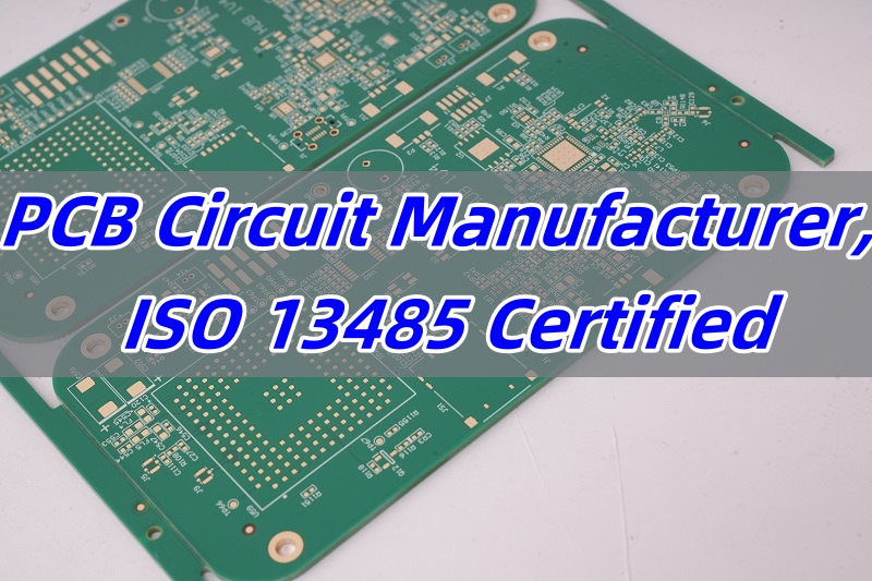
Are you looking for multi layer PCB manufacturer that provides with fast delivery service? As technology advances, the demand for multi layer PCBs (Printed Circuit Boards) continues to grow. These boards are essential in modern electronics, offering superior performance and reliability compared to single-layer or double-layer PCBs. In this blog, we’ll explore what makes a multi-layer PCB manufacturer the best choice, the materials used in their production, how long it takes to manufacture them, and why you should select EBest Circuit (Best Technology) as your trusted partner.
EBest Circuit (Best Technology) is your reliable multi layer PCB manufacturing partner with on-time delivery service. Our multi layer PCB quality is in line with AS9100D aerospace standards. We have good inventory management for the customer material. Our commitment is to provide high-quality PCB manufacturing and turnkey PCB assembly service to our global customers from rapid PCB Prototyping, and component sourcing to PCBA. Our engineers master the know-how, and we are happy to not only provide the final multi layer PCBs, but also the tailored multi layer PCB solutions for your applications. If you are looking for multi layer PCB manufacturer with fast delivery, kindly reach out to us at sales@bestpcbs.com.
1. What is the Best Multi Layer PCB Manufacturer?
In the dynamic world of electronics, multi layer printed circuit boards (PCBs) play a crucial role. They are the backbone of countless electronic devices, from smartphones and laptops to industrial machinery and aerospace equipment. But with so many PCB manufacturers out there, how do you determine the best multi layer PCB manufacturer? Let’s dive in and explore the key factors and some top contenders.
1. Technical Expertise
- Design Capabilities: The best multi layer PCB manufacturers have a team of highly skilled designers. These experts can handle complex PCB designs, ensuring proper signal integrity, power distribution, and thermal management. For example, they can design multi layer boards with high speed signal traces, which are crucial for modern high performance electronics.
- Manufacturing Processes: Advanced manufacturing processes are a must. This includes capabilities such as precise drilling, electroplating, and solder mask application. A manufacturer that uses state-of-the-art equipment can produce multi layer PCBs with tight tolerances and high reliability.
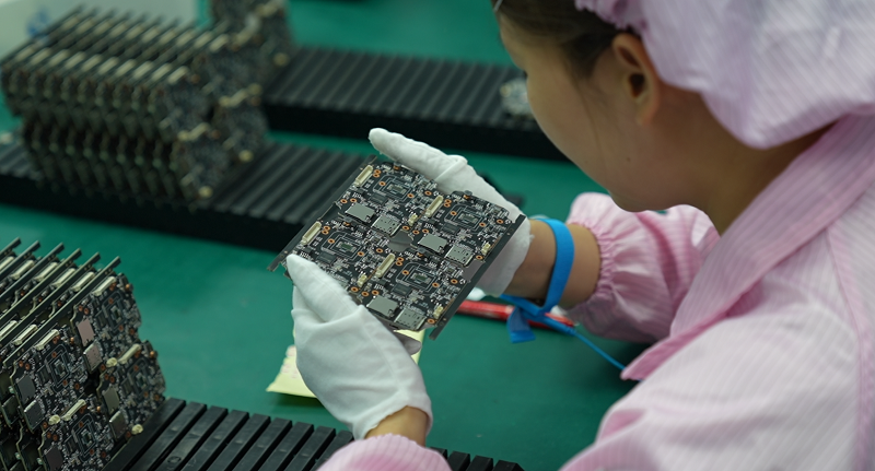
2. Quality Assurance
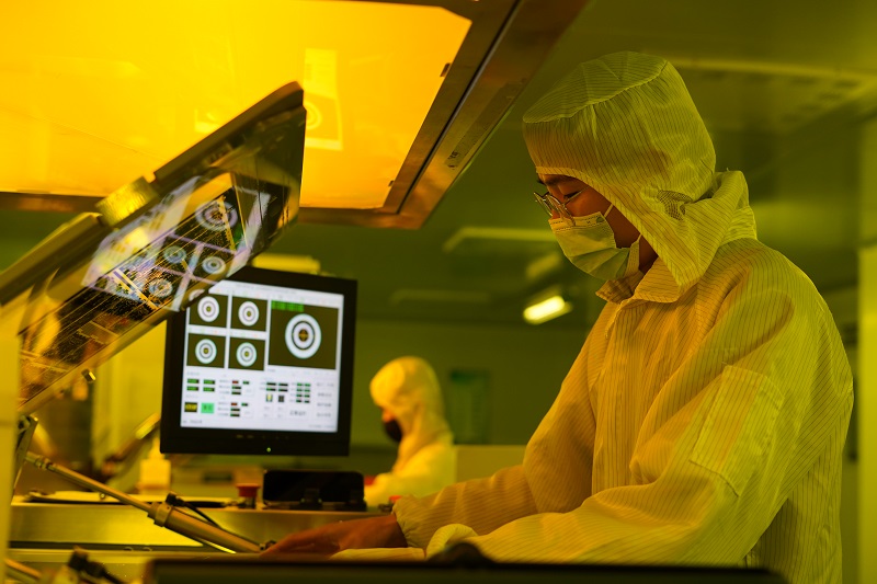
- Testing Procedures: Rigorous testing is essential to ensure the quality of multi layer PCBs. The best manufacturers conduct a variety of tests, such as electrical testing, X-ray inspection, and automated optical inspection (AOI). These tests help detect any defects, such as short circuits, open circuits, or incorrect component placement.
- Certifications: Certifications like ISO 9001, IPC standards, and RoHS compliance are indicators of a manufacturer’s commitment to quality. ISO 9001 ensures that the manufacturer has a well-defined quality management system in place, while IPC standards guarantee that the PCBs meet industry-recognized quality levels.
3. Production Capacity and Turnaround Time
- Capacity: A good multi layer PCB manufacturer should have sufficient production capacity to meet your volume requirements. Whether you need a small batch of prototypes or large-scale production runs, they should be able to handle it.
- Turnaround Time: In today’s fast-paced market, quick turnaround times are crucial. The best manufacturers can deliver your multi-layer PCBs in a timely manner, without compromising on quality. This is especially important for companies with tight product launch schedules.
4. Customer Service
- Communication: Clear and effective communication is key. The manufacturer should be responsive to your inquiries, provide regular updates on the production progress, and be willing to work with you to address any issues or concerns.
- Technical Support: Good technical support can make a big difference. Whether you need help with PCB design, troubleshooting, or understanding the manufacturing process, the manufacturer should have a team of experts available to assist you.
Choosing the right multi-layer PCB manufacturer is crucial for ensuring high-quality products that meet your specific requirements. EBest Circuit (Best Technology) stands out due to its extensive experience, advanced manufacturing capabilities, and commitment to customer satisfaction. With over 18 years of expertise in the PCB industry, EBest Circuit (Best Technology) offers reliable and efficient solutions tailored to various applications, from prototypes to mass production.
2. Multi Layer PCB Manufacturers in India
Multi-layer PCBs have become essential components in modern electronics, powering everything from smartphones to aerospace systems. India manufacturers leverage local talent and advanced technology to produce boards that are competitive globally. However, selecting the right one requires careful evaluation of factors such as experience, production capacity, and quality control measures.
1. Micropack Limited
(Established:1984 | Location: Bangalore)
A pioneer in adopting advanced Orbotech Nuvogo DI technology, Micropack specializes in high-reliability boards for aerospace application. Their technical capabilities include:
- Advanced direct imaging solutions
- Quick turnaround prototyping
- Aerospace-grade multilayer boards
2. Ascent Circuits
(Established:1999 | Location: Hosur)
Recently secured ₹500 million investment for expansion, positioning them as leaders in automotive and telecom PCBs. Key highlights:
- Annual capacity:108000 multilayer boards
- Caters to ISRO, BEL, and major auto companies
- 23% revenue growth in FY2023
3. EIPRISM Circuitronics
(Established:1995 | Location: Pune)
A specialized manufacturer producing boards with up to 32 layers, particularly for space applications . Their expertise includes:
- High-density interconnect (HDI) technology
- Edge plating boards
- Serving aerospace sector
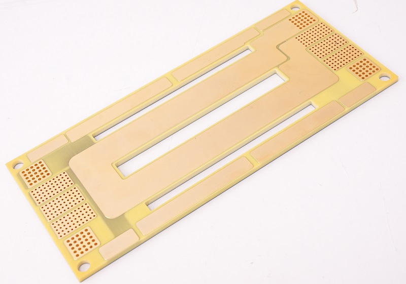
3. What Materials Are Used in Multi Layer PCB?
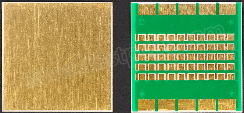
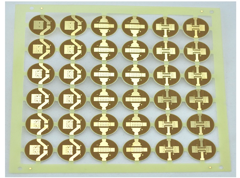
Multi-layer PCBs are typically made from a combination of copper foil, insulating materials (like epoxy glass cloth), and prepreg layers. These materials are carefully selected to ensure durability, thermal stability, and electrical conductivity. The core layers are usually made from epoxy glass fabric, while the outer layers consist of copper foil bonded with insulating materials. This multi-layer structure allows for efficient signal routing and electromagnetic interference (EMI) shielding.
4. How Long Does It Take to Manufacture Multi Layer PCBs?
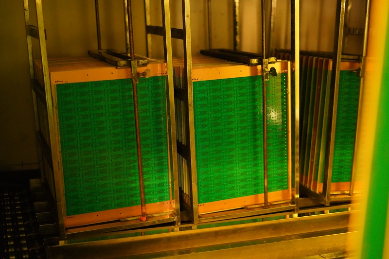
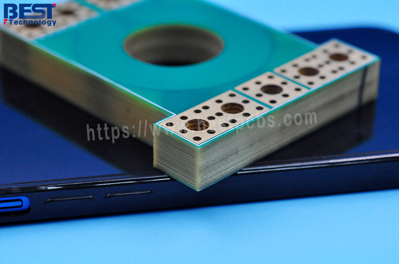
The manufacturing process of multi-layer PCBs is intricate and time-consuming. It involves several stages, including the design stage, layer creation, lamination, drilling, plating, etching, and final assembly. Depending on the complexity of the design and the number of layers, the production time can range from a few days to several weeks. For instance, the simple 4-layer prototypes might take around 7-10 business days, while more complex designs with eight layers or more layers could take up to 12 days or more. If you want to know more specific lead time of your demands, kindly contact us at sales@bestpcbs.com.
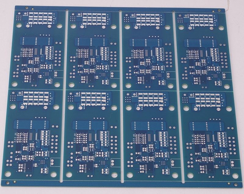
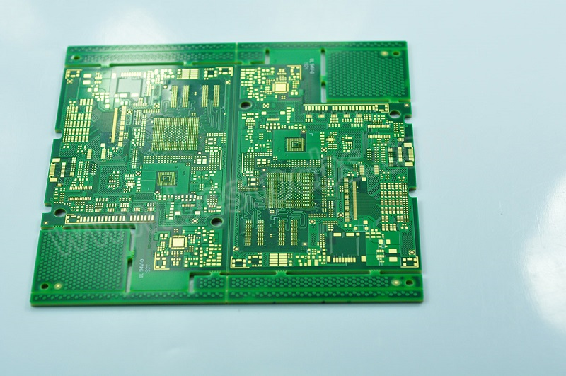
5. How Are 4 Layer PCBs Made?
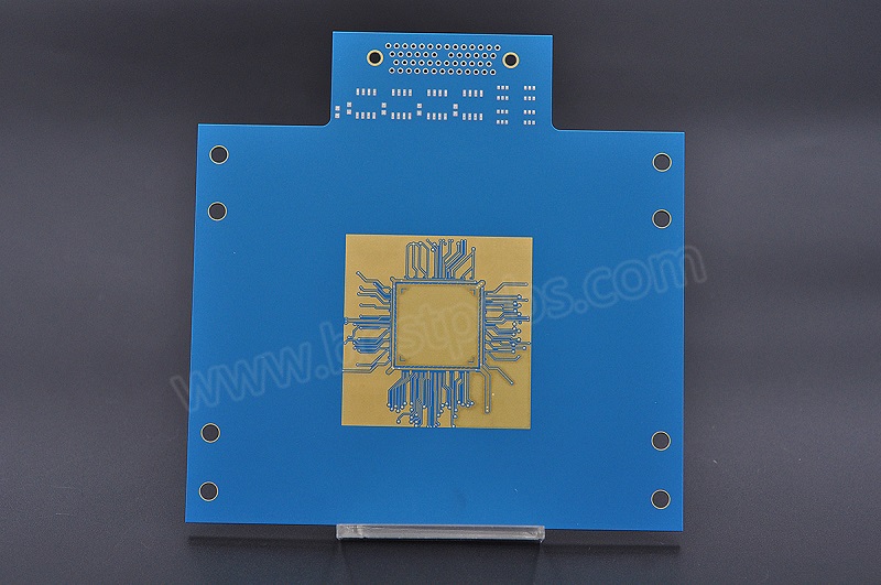
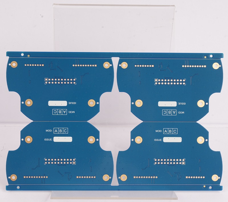
Manufacturing a 4-layer PCB involves several key steps:
- Design Planning: Engineers create a detailed blueprint using specialized software to ensure accurate routing and component placement.
- Core Layer Preparation: Two inner layers are prepared by applying copper foil on both sides of an epoxy glass substrate.
- Lamination: The inner layers are bonded together with prepreg material under high pressure and temperature to form a single unit.
- Drilling and Plating: Holes are drilled for vias, followed by electroless copper plating to connect the layers.
- Etching: Excess copper is removed to create the desired circuit pattern.
- Final Assembly: The outer layers are laminated onto the core layers, followed by silk screening, solder mask application, and testing.
6. How to Choose a Multi Layer PCB Manufacturer?
Choosing the right manufacturer involves considering several factors:
- Experience: Look for manufacturers with a proven track record of delivering high-quality products.
- Capacity: Ensure they have sufficient production capacity to meet your order requirements.
- Technology: Opt for manufacturers using advanced equipment and processes like CNC testing and FQC packaging.
- Customization: Choose providers that offer flexible customization options to suit your unique needs.
- Request Quotes: Contact multiple manufacturers and request detailed quotes. Compare the pricing, services, and delivery times offered by each manufacturer.
- Support: Evaluate their customer support and response time to ensure timely assistance.
- On – Site Inspection: If feasible, visit the manufacturer’s facility. This will give you an opportunity to see their production processes, quality control measures, and the overall working environment. It can also help you establish a better relationship with the manufacturer.
In conclusion, finding the best multi layer PCB manufacturer requires careful consideration of various factors. By evaluating technical expertise, quality assurance, production capacity, customer service, you can make an informed decision that meets your specific needs. You can select an established global player such as EBest Circuit (Best Technology), and the right choice will make a big difference to the success of your electronic project.
7. Why Should You Choose EBest Circuit (Best Technology) as Your Trusted Multi Layer PCB Manufacturer?
EBest Circuit (Best Technology) excels in providing top-notch multi-layer PCB manufacturing services due to its:
- Extensive Experience: Over 18 years of expertise in PCB manufacturing ensures reliability and efficiency. We provide one-stop services such as design, layout, prototyping, PCBA, and box build assembly.
- Advanced Equipment: State-of-the-art machinery enables precise manufacturing processes.
- Custom Solutions: Offers tailored solutions for various applications, including aerospace, telecommunications, and medical devices. We provide high-quality PCBs, like extra thin PCB, HDI PCB, high TG PCB, RF PCB, etc.
- Global Reach: Serves clients worldwide with on-time delivery.
- Quality Assurance: We follow strict quality control standards, from raw materials to final product testing. We comply with environmental regulations. All materials are lead-free and comply with UL, REACH, and RoHS standards. Moreover, our plants comply with international standards like ISO 9001, ISO 13485, IATF 16949, and AS9100D to ensure consistent quality.
- Production Capacity: Our current monthly production capacity is 260,000 square feet (28,900 square meters), allowing us to complete over 1,000 distinct PCB boards.
By partnering with EBest Circuit (Best Technology), you can trust that your multi-layer PCBs will be manufactured with precision, reliability, and adherence to your specifications. Whether you need prototypes or mass production runs, EBest Circuit (Best Technology) is your one-stop solution for all your PCB manufacturing needs.
In conclusion, finding a reliable multi layer PCB manufacturing partner with on-time delivery service is of significance to ensure the success of your project. By choosing a provider who not only provides high-quality products but also offers fast turnaround PCB Manufacturing services, you can be confident that your end product will meet the demanding timelines and expectations set by your client or market demand. This kind of partnership not only enhances customer satisfaction but also opens up new opportunities for growth and expansion within your business. EBest Circuit (Best Technology) is committed to delivering aerospace-grade quality PCBs and providing solutions for all series of PCBs. You can contact us at sales@bestpcbs.com. Thanks so much for your trust.