PCB manufacturing PCB manufacturing
Home > Blog

Archive for the ‘bestpcb’ Category

Happy 19th Anniversary to Best Technology!!!
Monday, June 30th, 2025

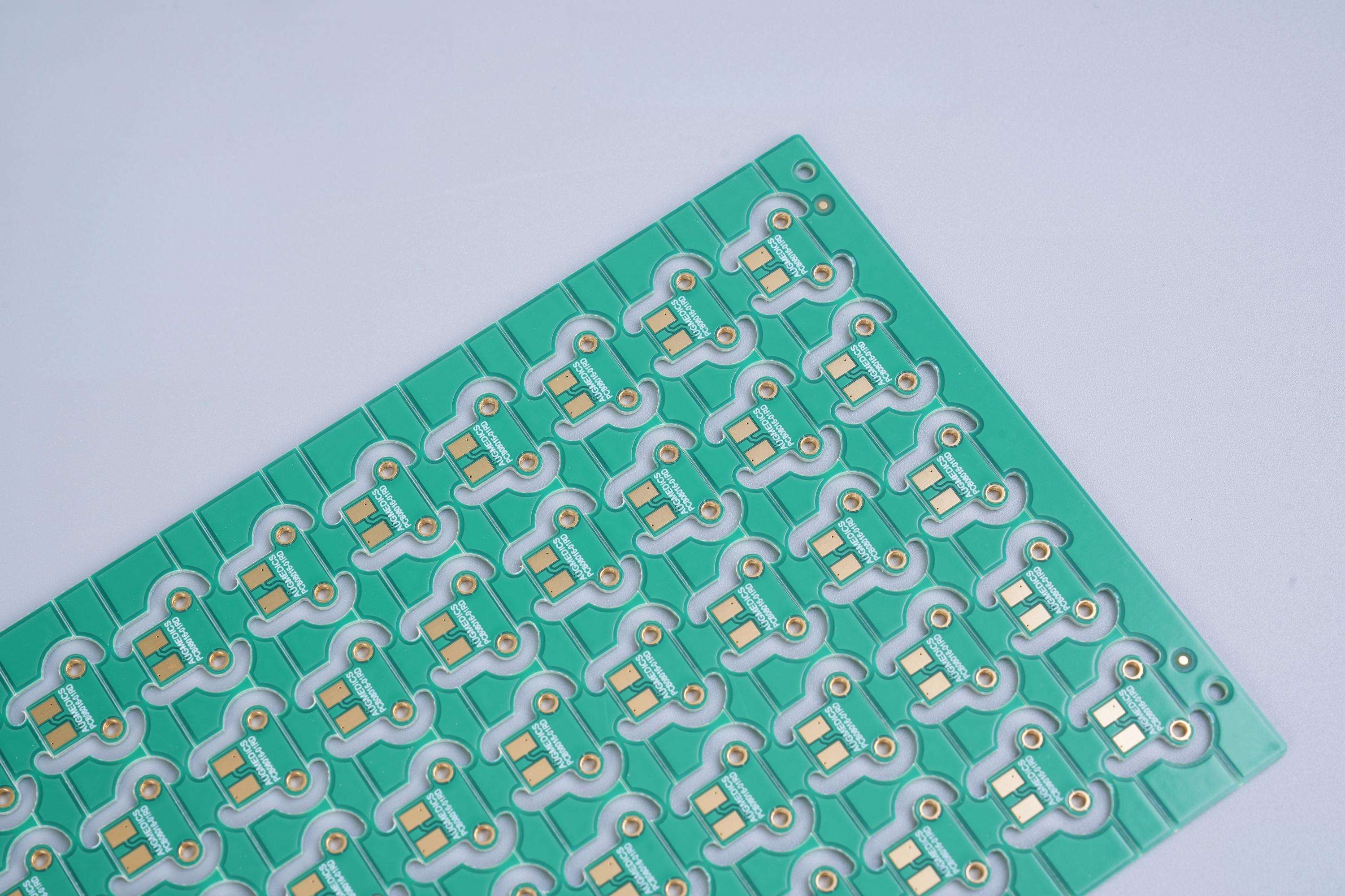
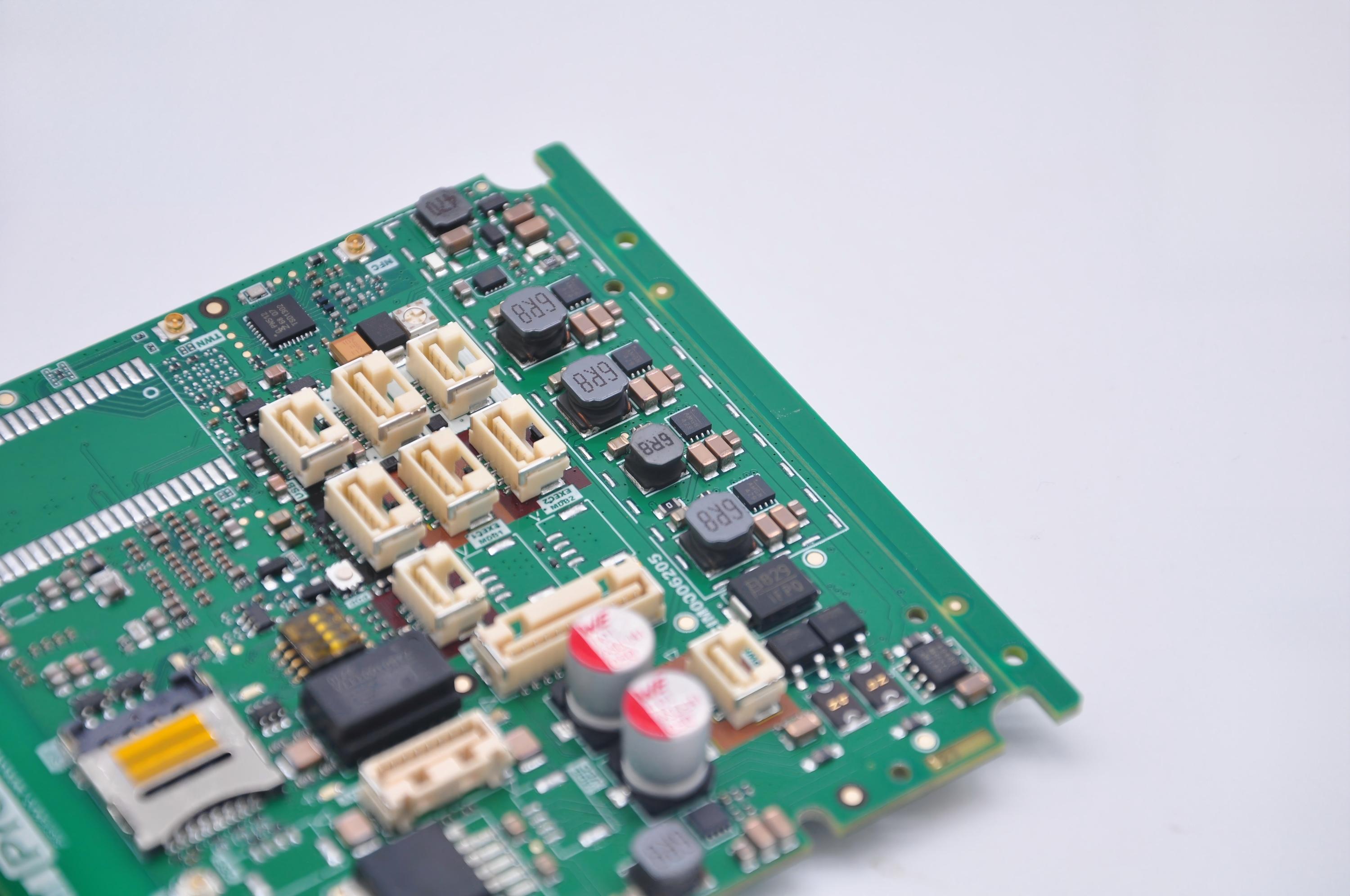
Last Saturday, Jun 28th, 2025, we are thrilled to celebrate the 19th anniversary of Best Technology both in our factory and office. It has been an inspiring journey of innovation, perseverance, and continuous growth since our company was officially established on June 28, 2006, in Hong Kong. What started as a small team with a single product line has now become a leading printed circuit board (PCB) and assembly service provider trusted by hundreds of global customers.

Our Growth Capability

In the early days, Best Technology focused on producing metal dome switches, with only one staff member and a very small office. Our scale was small, but our vision was big: to become a reliable, long-term PCB manufacturing partner that values quality, precision, and speed.

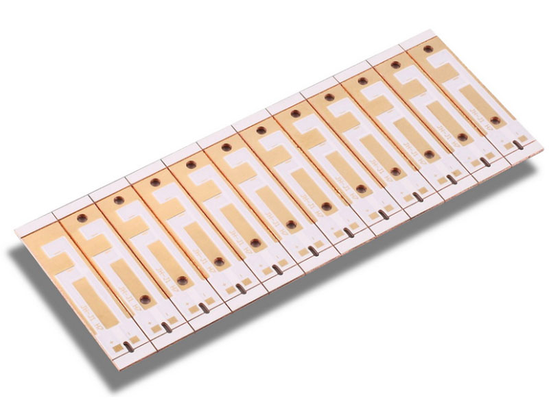
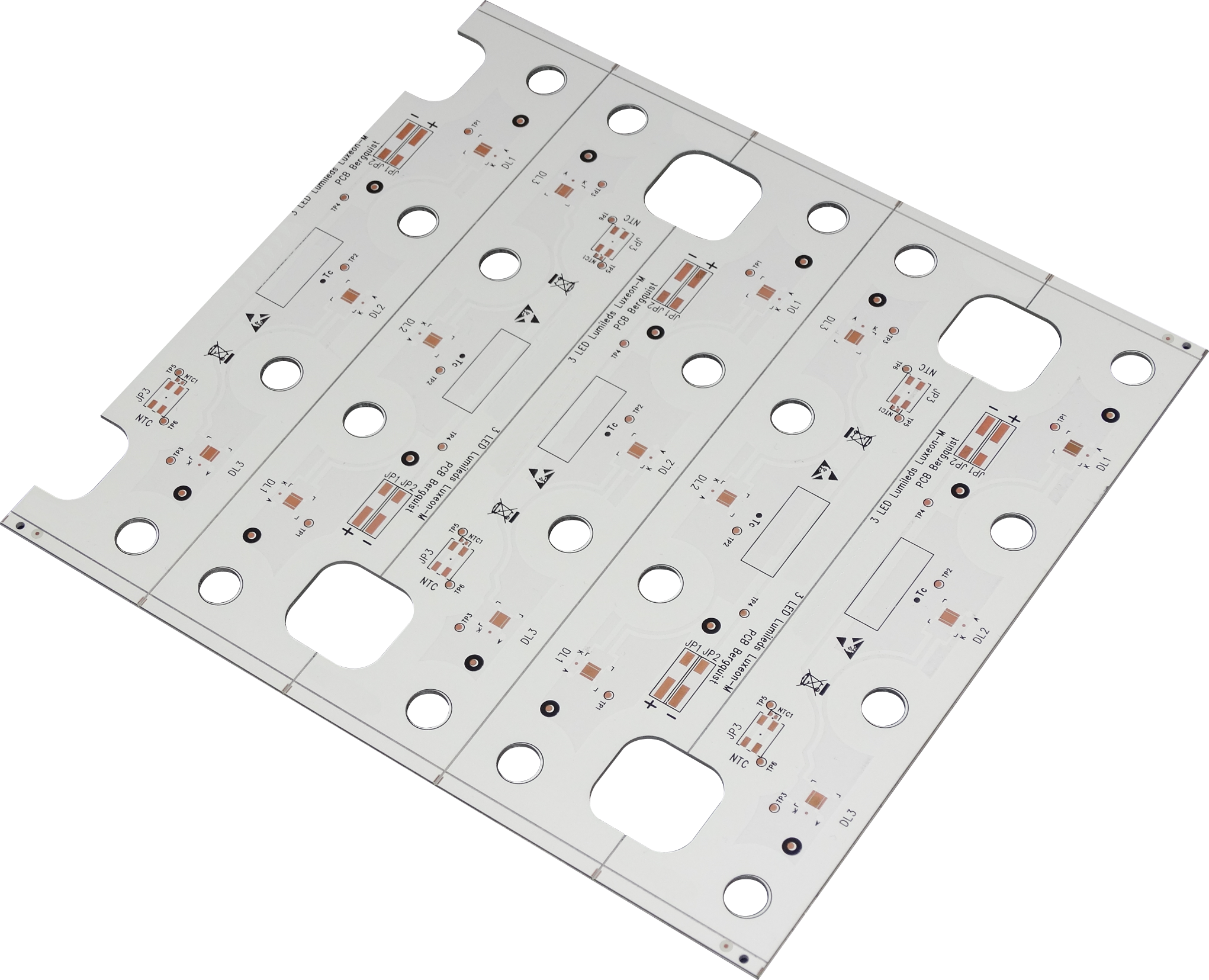
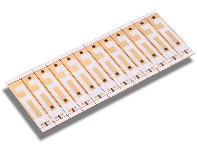
As time passed, our capabilities matured. We gradually expanded our product lines from metal domes to FR4 PCBs, Heavy Copper PCBs, Flexible Circuits (FPC), Rigid-Flex PCBs, Metal Core PCBs (MCPCBs), Ceramic PCBs and built a SMT factory, aiming to provide customer with one-stop service. Today, we are proud to support a wide range of industries including automotive, medical, aerospace, LED lighting, industrial control, power electronics, and many more.

Solid Team Backed us

One of our most valuable assets is our people. From a single founder Peter to a dedicated team of over 100 skilled professionals, our growth has been powered by individuals who care deeply about every board we produce. Most of our engineers and production staff have over 10 years of experience, enabling us to tackle even the most complex and high-precision PCB projects. Here are some our office staff.

To support increasing demand and advanced technical requirements, we’ve continually invested in state-of-the-art production equipment and testing instruments. Today, we operate dozens of machines that help us deliver:

  • 20 OZ heavy copper PCBs
  • 4-layer metal core PCBs
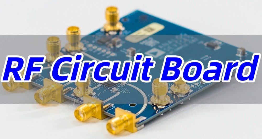
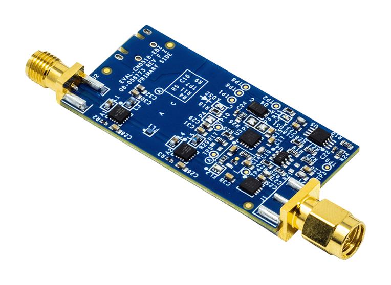
  • High-frequency Rogers and Taconic boards
  • Controlled impedance multilayers
  • Quick-turn prototypes within 24 hours

With over 260,000 square feet of monthly production capacity and a strict ISO9001, ISO13485, IATF16949, and AS9100D certified quality system, we ensure our boards meet the highest international standards.

Growing Together with Global Customers

As we’ve grown, so has our customer base. From serving a handful of clients locally, we now support hundreds of customers across Asia, Europe, North America, and Oceania. Many of our customers are long-term partners who appreciate our fast delivery, consistent quality, and professional engineering support.

We are especially proud to have built strong relationships with companies in medical electronics, military and defense systems, communication devices, and green energy products, helping them bring reliable and high-performance solutions to market.

We Offer Turnkey PCB Solutions

Best Technology is not just a PCB manufacturing. We’re a one-stop solution provider. Over the past 19 years, we’ve expanded our services to include:

  • PCB duplication and layout
  • Engineering and process design
  • Component sourcing and BOM management
  • In-house SMT and DIP assembly
  • Full system integration and final product assembly

This comprehensive capability allows us to assist customers from initial concept to final product shipment, saving them time, cost, and communication hassle.

Looking Back with Pride, Looking Ahead with Confidence

Nineteen years may sound like a long time, but for us, this is only the beginning. With each passing year, we’ve learned, improved, and evolved. From manual operations to fully digitized and MES-monitored workflows, from domestic sales to a global footprint, Best Technology has transformed into a modern, competitive, and customer-focused enterprise.

We are grateful to every employee who contributed to our growth, and to every customer who chose to trust us. Your continued support is the reason we are here today, celebrating this special milestone.

As we look forward to the future, we remain committed to:

  • Continuous innovation
  • Advanced manufacturing capabilities
  • Rigorous quality control
  • Flexible and responsive customer service

Thank You for Being Part of Our 19-Year Journey

We believe that the best is yet to come. As we step into our 20th year, we invite you to grow with us, explore new ideas together, and build even stronger partnerships.

Whether you need standard FR4 PCBs, high-power heavy copper boards, high-frequency circuits, or custom PCB assembly solutions — Best Technology is always ready to be your reliable manufacturing partner.

👉 Have a project in mind? Contact us today to find out how we can help bring your vision to life.

Happy 19th Anniversary to all of us at Best Technology!

Extraordinary Quality China PCBA for Efficient Delivery
Monday, June 30th, 2025

China PCBA solutions are changing how electronics manufacturers think about speed, quality, and reliability. In this blog, we’ll explore how Best Technology delivers professional SMT PCBA manufacturing, driven by cutting-edge systems and a commitment to excellence.

Best Technology is a leading PCB & PCBA Manufacturer offering extraordinary quality China PCBA for efficient delivery. We place a priority on innovation and have a professional research and development department that has been creating patents annually, thanks to our seasoned talents. Best Technology promotes team spirit and provides quick responsiveness service to both our prospects and regular customers. We implement shift work at our SMT PCBA factories in China & Vietnam, where the on-time delivery rate is up to 97%. Both factories are ISO 9001, ISO 13485, IATF 16949, and AS9100D compliant. Rest assured that we can effectively handle both large and small-volume orders. Feel free to contact us at sales@bestpcbs.com for any technical inquiries or requests to make a factory visit. We are happy to give our full engagement and show you around our factory at your convenience.

Extraordinary Quality China PCBA for Efficient Delivery

What is the best China PCBA company?

The best China PCBA company combines speed, quality, and dependability. Best Technology is a standout in the industry. We use full-process digital quality control to reach nearly perfect production efficiency. Our first-pass yield exceeds 99.9%, thanks to precise control and minimal human error. We also offer a stable lead time of 7 days, meeting the demand of fast-moving industries without sacrificing quality. Our customer satisfaction rate reaches 98%, a result of responsive technical support and after-sales service.

What is the best China PCBA company?

Who is the best China PCBA supplier?

Best Technology is recognized as a leading China PCBA supplier. We serve global markets with robust PCBA services including design, sourcing, assembly, and testing. With certifications like ISO 13485, AS9100D, and IATF 16949, we meet the standards required for medical, aerospace, and automotive industries. Our systems trace each PCB with a unique ID, speeding up issue tracking by 90%. We also deploy AOI, SPI, and X-ray inspection for a 99.97% defect capture rate.

Who is the largest China PCBA manufacturer?

China has many large PCBA manufacturers, each with strengths in different sectors. Below are three major players:

  1. Shenzhen Kaifa Technology: Known for large-scale EMS, they serve telecom and consumer electronics. They focus on smart manufacturing and rapid delivery.
  2. Huaqiang Electronics: A major supplier in the China PCB market. They offer complete solutions from design to PCBA assembly, including sourcing and testing.
  3. BYD Electronics: Originally an automotive company, they now provide PCBA services across industries, offering strong R&D and automated lines.

These companies provide large-scale services, but many customers prefer more responsive and flexible partners like Best Technology. With lean production lines and quick delivery, we give more attention to individual projects.

Who is the largest China PCBA manufacturer?

What is the difference between a PCB and a PCBA?

The key term here is PCBA vs PCB. A PCB (Printed Circuit Board) is the blank board with copper traces. A PCBA (Printed Circuit Board Assembly) includes all mounted components like resistors, chips, and connectors. So, PCBA is a complete working circuit. We not only produce PCBs but also handle sourcing, assembly, and testing to deliver complete PCBA products ready for integration.

What are the problems with PCBA?

Every manufacturer faces challenges. Here’s a breakdown of common PCBA issues and their impacts:

ProblemImpact
Unstable qualityHigh defect rate reduces reliability
Soldering issues (cold joints, voids, etc.)Account for over 60% of total defects
No traceability78% of companies cannot locate root causes, leading to long rework time
Manual inspection dependencyYield rate fluctuates over 15%
Uncontrolled delivery schedulesComponent lead time causes 65% of delays
Frequent reworkCauses 3–5 days of delivery delay
Cost vs quality conflictTrying to cut costs may raise defect rates

Best Technology addresses all these problems with digital inspection, predictive maintenance, and robust logistics support.

How expensive is China PCBA?

The cost of China PCBA depends on complexity, parts, and order size. However, Best Technology balances price and quality well. We apply lean production, centralized sourcing, and predictive logistics to cut unnecessary costs. Our long-term vendor relationships help us get better prices, which we pass on to our clients.

Is BEST in China?

Yes, Best Technology is based in China. We operate a modern facility equipped with advanced SMT lines, X-ray, AOI, SPI, and MES systems. We serve both domestic and global clients with end-to-end PCBA services. Our location in Shenzhen offers fast access to electronic components and efficient shipping options.

Why choose Best Technology for China PCBA?

We go beyond manufacturing. Here’s why customers choose us:

  • Stable quality: Achieved through full-process digital control and triple inspection systems.
  • Fast delivery: 7-day lead time with intelligent supply chain and emergency line setup.
  • High reliability: Our defect rate stays below 0.1%, even for complex builds.
  • Component sourcing: Over 500 supplier partners and predictive stock ensure parts availability.
  • Responsive support: 24/7 technical help with direct engineer contact, reducing wait time.
  • Customization: Flexible solutions for medical, automotive, LED, and other specialized applications.

Our system offers not just production but a total solution. From fast prototyping to volume orders, we keep communication simple and outcomes consistent. When other suppliers struggle with delays or defects, we bring stability and precision.

Why choose Best Technology for China PCBA?

To wrap up, China PCBA services are efficient, but not all manufacturers deliver the same results. Thorough supplier vetting is vital to maintain consistent quality standards. Best Technology provides viable solutions to customers—from digital traceability to fast delivery and high reliability. We shorten delivery times by 53% and improve quality by over 70%. If you’re looking for dependable PCBA manufacturing in China, Best Technology is your next move. Just feel free to let us know your specific SMT PCBA requirements via sales@bestpcbs.com.

BMS PCB Protection Board for 18650​
Monday, June 30th, 2025

How BMS PCB keeps your 18650 battery pack safe and efficient?‌ This guide covers everything from wiring and design to cost-effective noise shielding and heat management for optimal BMS PCB protection.

Using 18 years of BMS PCBA technology accumulation, we will protect your battery safety!

  • Poor welding? – Nitrogen reflow + 3D SPI detection to eliminate false welding
  • Delivery delay? – Intelligent scheduling system guarantees 7-day delivery
  • Cost out of control? – Standardized process reduces 15% assembly cost
  • Poor compatibility? – Support TI/ADI/NXP and other multi-platform solution adaptation

Best Technology Provide:

  • Integrated solution – From PCB design to finished product assembly, BMS protection board “plug and play” is realized
  • High-precision mounting – 01005 component mounting accuracy ±25ÎŒm, ensuring the stability of the sampling circuit
  • Triple test guarantee – AOI+ICT+FCT full inspection, fault interception rate increased to 99.97%
  • Flexible production – Support 1-16 layer board mixed production, 24-48 hours ultra-fast prototyping.

Let every BMS PCB become the intelligent guardian of the battery system! Contact us now: sales@bestpcbs.com.

What Is BMS PCB?

A BMS PCB (Battery Management System Printed Circuit Board) serves as the central control unit for rechargeable battery packs, ensuring safe and efficient operation. It monitors vital parameters including individual cell voltages, overall current flow, and temperature distribution across connected battery cells. When detecting potentially hazardous conditions such as overcharging, excessive discharge, or abnormal heat buildup, the system automatically disconnects the battery through integrated protection circuits to prevent permanent damage.

To maintain consistent performance, most BMS PCBs incorporate cell balancing functionality, which adjusts charge distribution among cells during operation. This process helps maximize available energy storage while extending battery lifespan. Communication capabilities allow the board to relay operational data, including state-of-charge estimates and system warnings, to connected devices through standard interfaces. The implementation varies across applications, with simpler versions managing small consumer electronics and more advanced configurations supporting high-capacity systems like electric vehicles and renewable energy storage installations.

What Is BMS PCB?

How to Wire PCB BMS?

Here’s a practical guide to wiring a BMS PCB, focusing on achieving reliability, safety, and performance:

1. Establish Accurate Cell Voltage Monitoring

  • Connect each cell voltage sense wire directly to its corresponding cell terminal within the battery pack. Keep these sense wires as short and consistent in length as feasible and route them away from high-current paths to minimize noise interference and ensure precise voltage readings by the BMS PCB.

      2. Implement Dedicated High-Current Paths

      • Use appropriately thick traces or busbars for the main battery pack positive (P+) and negative (P-) connections entering the BMS PCB. Similarly, size the discharge (B-) and charge/discharge output (C- or P-) traces adequately to safely carry their maximum expected currents without excessive voltage drop or heating.

      3. Apply Effective Grounding Strategies

      • Create a solid, low-impedance reference ground plane on the BMS PCB near the current shunt resistor. Physically separate and connect sensitive analog measurement grounds (like cell sense circuits) directly to this reference point before connecting noisy digital grounds or high-current FET grounds.

      4. Route Signal Traces Mindfully

      • Physically separate sensitive signals like cell voltage sense lines. Shield communication lines (CAN, UART, etc.) whenever possible using twisted pairs, shielded cables, or ground planes adjacent to the traces on the BMS PCB itself.

      5. Install Thermistors Securely

      • Mount temperature sensors directly onto the cell surface or module terminals where thermal monitoring is required. Route their connecting wires carefully to avoid snagging or damage and connect them securely to the designated thermistor input pins on the BMS PCB.

      6. Connect Balancing Components Efficiently

      • Link balancing resistors or FETs directly to their respective cell sense points. Ensure the balancing current paths on the BMS PCB have adequate trace width for the balancing current level without causing localized heating. Tightly group balancing components to shorten signal paths.

      7. Select and Wire Suitable Connectors

      • Choose connectors rated well above the maximum operating current and voltage, with sufficient pin density and locking mechanisms. Match wire gauges to current loads. Clearly label all connector positions for unambiguous wiring to the BMS PCB.

      8. Integrate Protective Elements

      • Install necessary fuses or circuit breakers in series with the main pack positive (P+) input path before it reaches the BMS PCB. Ensure the fuse rating aligns with system capabilities. Connect any external contactor control coils to the designated driver outputs on the BMS PCB.

      9. Verify Connections Thoroughly

      • Before applying power, meticulously check all wiring against the BMS PCB schematic and layout diagram. Use a multimeter to confirm absence of short circuits, verify correct voltage polarity at each sense point, and ensure thermistor resistances read correctly at the connector.

      How to Design BMS PCB Heat Dissipation Structure to Avoid MOSFET Hot Spot Failure?

      Here are practical approaches to design BMS PCB heat dissipation structures that effectively prevent MOSFET hot spot failures:

      • Strategic Component Placement: Position MOSFETs away from other heat-generating components and near board edges or ventilation areas. Allow sufficient spacing between devices to enable airflow and prevent thermal interference.
      • Optimized Copper Pour Layout: Use thick copper layers (≄2 oz) for power traces and create large, continuous copper areas connected to MOSFET source/drain pins. Expand these pours to maximize surface area for heat dissipation.
      • Thermal Via Implementation: Place dense arrays of thermal vias beneath MOSFET packages, connecting top-side heat sources to inner copper layers or bottom-side heatsinks. Follow manufacturer recommendations for via diameter and spacing.
      • Effective Heatsink Integration: Design PCB mounting points for clip-on or screw-attached heatsinks. Ensure flat surface areas under MOSFETs for proper thermal interface material contact when using external cooling solutions.
      • Current Distribution Balancing: Implement symmetrical layouts with identical trace lengths when using parallel MOSFETs. This prevents uneven current sharing that could cause localized overheating in individual devices.
      • Thermal Relief Pad Design: Configure solder pads with appropriate thermal relief patterns – enough to allow proper soldering while maintaining efficient heat transfer to the PCB copper.
      • Temperature Monitoring Integration: Embed temperature sensors near expected hot spots, positioned to detect actual MOSFET case temperatures rather than ambient board temperature for accurate thermal management.
      How to Design BMS PCB Heat Dissipation Structure to Avoid MOSFET Hot Spot Failure?

      How to Shield BMS PCBs from High-Voltage Noise Without Breaking the Budget?

      Cost-effective strategies to shield BMS PCBs from high-voltage noise

      Prioritize TVS Diodes for Transient Voltage Suppression

      • Implementation: Install TVS diodes at power inputs and critical signal lines (e.g., CAN bus, sensor interfaces).
      • Why: Clamps high-voltage spikes from load dumps or inductive switching, diverting excess energy to ground.
      • Cost Efficiency: Low-cost unidirectional/bidirectional TVS arrays (e.g., SMAJ series) provide robust protection without complex circuitry.

      Optimize PCB Layout for Noise Isolation

      • Ground Plane Strategy: Use dedicated ground layers for analog/digital sections. Separate high-current paths (e.g., battery cell balancing) from low-voltage sensor traces.
      • Trace Routing: Keep high-voltage traces >2mm from sensitive signals. Avoid 90-degree bends to minimize impedance discontinuities.
      • Decoupling: Place 0.1”F ceramic capacitors near every IC power pin and 10”F electrolytic capacitors at PCB entry points.

      Leverage Ferrite Beads for HF Attenuation

      • Application: Insert ferrite beads (e.g., Murata BLM series) in series with power lines to the MCU and communication modules.
      • Benefit: Dissipates high-frequency noise as heat without affecting DC power delivery.
      • Budget Tip: Use multi-layer chip inductors (e.g., 1206 size) for cost-effective EMI filtering.

      DIY Shielding with Copper Tape or Aluminum Enclosures

      • Low-Cost Enclosure: Line BMS housing with adhesive copper foil (≀$5 for 1mÂČ) and connect to PCB ground.
      • Gap Management: Seal seams with conductive gasket tape to prevent electromagnetic leakage.
      • Alternative: Repurpose aluminum tooling plates as shields, secured with nylon screws to avoid ground loops.

      Software Filtering for Noisy Sensors

      • Algorithm: Implement a moving average or Kalman filter in BMS firmware to smooth voltage/current readings.
      • Example: Apply a 10-sample moving average to cell voltage data to reject transient spikes from motor noise.
      • Zero Hardware Cost: Leverage unused MCU flash memory to store filter coefficients.

      Isolation Techniques for Critical Nodes

      • Optocouplers: Use low-cost optoisolators (e.g., PC817) for relay drivers or charge enable signals.
      • Digital Isolators: For CAN/RS-485 interfaces, adopt cost-effective isolators like ISO7741 (under $2 in qty).
      • Galvanic Separation: Prevent ground loops by isolating high-voltage sampling circuits from the main MCU.

      What Is A BMS Protection PCB Board?

      A BMS protection PCB board is a dedicated hardware solution designed to ensure battery pack safety by monitoring critical parameters in real time. This printed circuit board tracks cell voltages, pack current, and temperature distribution while comparing these values against predefined safety thresholds. When detecting unsafe conditions like overvoltage, undervoltage, excessive current, or high temperatures, it activates protective measures through control elements such as power MOSFETs to isolate the battery. The board also incorporates cell balancing functions, state-of-charge estimation, and communication interfaces to relay system status. Its primary purpose is to provide autonomous hardware-level protection that prevents catastrophic failures while maintaining safe battery operation.

      What Is A BMS Protection PCB Board?

      How to Use PCB BMS Protection Board for 18650s?

      How to use a PCB BMS protection board for 18650 batteries:

      1. Inspect the BMS and Batteries

      • Confirm the BMS matches your 18650 cell count (e.g., 4S for four 3.7V cells in series).
      • Check battery voltage with a multimeter to ensure no cell is below 2.5V before connecting the BMS.

      2. Wire the Battery Pack

      • Connect the battery pack’s negative terminal to the BMS B- port using 16–20 AWG silicon wire.
      • Route each cell’s balance wire (B1+, B2+, etc.) to the corresponding BMS balance ports. Avoid crossing wires to prevent short circuits.

      3. Connect Charger and Load

      • Attach the charger’s negative lead to the BMS P- port and positive lead to the battery pack’s positive terminal.
      • Connect the load (e.g., device, inverter) to the same P- port and pack positive, ensuring the load’s current draw does not exceed the BMS rating.

      4. Secure and Ventilate the BMS

      • Mount the BMS using nylon standoffs to prevent contact with metallic surfaces.
      • Ensure adequate airflow around the BMS, especially if it lacks built-in heat sinks.

      5. Initial Power-Up and Testing

      • Charge the pack at 0.5A–1A initially to verify the BMS triggers overcharge protection at 4.25V per cell.
      • Discharge the pack with a low-power load (e.g., LED light) to test over-discharge cutoff at 2.5V per cell.

      6. Balance Cells Regularly

      • After 3–5 cycles, use a battery analyzer to check cell voltages. Manually discharge any cell exceeding 4.2V using a resistor.
      • Avoid full discharges to minimize voltage imbalance between cells.

      7. Monitor Temperature and Connections

      • Check for overheating near MOSFETs during high-current use. Reduce charge/discharge current if temperatures exceed 60°C.
      • Tighten terminals monthly to prevent loose connections, which can cause erratic behavior.

      8. Replace Aging Components

      • Inspect capacitors for bulging every 12 months. Replace if signs of leakage or swelling appear.
      • Upgrade to a BMS with higher current ratings if using the pack for high-drain applications (e.g., e-bikes).

      How to Choose PCB BMS Protection Board for 18650?

      Match Cell Count and Voltage

      • Choose a BMS that supports your battery pack’s configuration (e.g., 4S for four 3.7V cells in series).
      • Verify the BMS’s maximum voltage rating exceeds your pack’s fully charged voltage (e.g., 16.8V for a 4S pack).

      Check Current Ratings

      • Select a BMS with a continuous discharge current rating 20% higher than your application’s peak demand (e.g., 30A BMS for a 25A e-bike motor).
      • Ensure the charge current rating aligns with your charger’s output (e.g., 5A BMS for a 4A charger).

      Evaluate Protection Features

      • Prioritize boards with overcharge, over-discharge, over-current, and short-circuit protection.
      • Look for optional features like cell balancing, temperature sensors, and low-voltage recovery modes.

      Inspect Physical Design

      • Choose a BMS with labeled terminals and spaced-out ports to simplify wiring.
      • Prioritize models with integrated NTC thermistor ports for precise temperature monitoring.

      Verify Communication Protocols

      • For smart packs, ensure the BMS supports your device’s protocol (e.g., I2C, SMBus) or includes Bluetooth/Wi-Fi for remote monitoring.
      • Test compatibility with your charger or energy meter before finalizing.

      Review User Feedback

      • Check forums or reviews for reports of false triggers, uneven balancing, or premature MOSFET failures.
      • Avoid boards with frequent complaints about solder joint quality or inaccurate voltage readings.

      Balance Cost and Longevity

      • Avoid ultra-cheap BMS units with thin traces or generic MOSFETs, as they may fail under stress.
      • Invest in models with replaceable fuses or upgradeable firmware for future-proofing.
      How to Choose PCB BMS Protection Board for 18650?

      How to Balance Cost and Stability of BMS PCB Protection Board for 18650​?

      Here are actionable tips to balance cost and stability when selecting a PCB BMS protection board for 18650 batteries:

      Prioritize Essential Protections Over Premium Add-Ons

      • Ensure the PCB BMS protection board includes core features: overcharge, over-discharge, over-current, and short-circuit protection. These are non-negotiable for safety.
      • Avoid paying extra for advanced functions like Bluetooth monitoring or active cell balancing unless your application requires them.

      Evaluate Component Quality Carefully

      • Check for MOSFETs with mid-range current ratings (e.g., 40V/60A vs. 80A+). They offer sufficient durability for most 18650 packs without inflating costs.
      • Look for ceramic capacitors instead of electrolytic ones for better temperature stability and longer lifespan.

      Balance Current Ratings with Real-World Needs

      • Choose a PCB BMS protection board with a continuous discharge rating 10–20% above your system’s maximum draw (e.g., 25A BMS for a 20A tool). This avoids over-engineering costs.
      • Avoid boards rated far beyond your requirements, as higher current tolerance often increases price disproportionately.

      Leverage Passive Cell Balancing

      • Opt for PCB BMS protection boards with passive balancing (resistor-based) instead of active balancing (inductor-based). Passive designs are cheaper and sufficient for most 18650 applications.
      • Ensure the balancing current is ≄50mA to maintain cell health over hundreds of cycles.

      Inspect Trace Width and PCB Thickness

      • Choose a board with 2oz copper traces and a minimum thickness of 1.6mm. These specs reduce resistance and heat buildup without adding significant cost.
      • Avoid ultra-thin PCBs (e.g., 0.8mm), as they may warp or delaminate under stress.

      Check for Replaceable Fuses or Resettable PTCs

      • Some PCB BMS protection boards include user-replaceable fuses or polymer PTCs (resettable breakers). These features extend the board’s lifespan by allowing recovery from overcurrent events.
      • Compare costs: A board with a $0.50 PTC may outlast three cheaper boards without this feature.

      Review Open-Source Firmware Options

      • Select a PCB BMS protection board with publicly available firmware (e.g., via GitHub). This lets you customize protections or fix bugs without relying on the manufacturer.
      • Community-supported boards often have lower long-term maintenance costs due to shared troubleshooting resources.

      Conclusion

      In conclusion, this guide has comprehensively covered the essential aspects of BMS PCB protection boards for 18650 battery systems, from fundamental concepts to practical wiring techniques, thermal management solutions, and cost-effective noise shielding approaches. We’ve explored proper usage methods, selection criteria, and the critical balance between performance and affordability. For reliable battery management systems that prioritize both safety and efficiency, these components prove indispensable. Should you require high-quality BMS PCB solutions tailored to your specific 18650 applications, we recommend contacting Best Technology for professional consultation and competitive pricing. Their expertise ensures optimal battery protection while meeting your technical and budgetary requirements. Welcome to contact us: sales@bestpcbs.com.

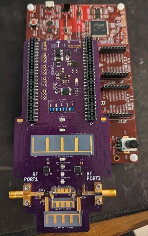
      STM32H7B3I DK, What Does STM32H7B3I-DK Mean?
      Friday, June 27th, 2025

      STM32H7B3I DK is a full-featured discovery kit built for developers who need high-performance control in embedded systems. It supports fast interface testing, GUI design, and efficient prototyping. Whether you are in industrial, consumer, or smart IoT sectors, this kit offers practical tools to bring your concepts to life.

      At Best Technology, we don’t just produce PCBs — we support engineers through manufacturing solutions for all sorts of PCB designs. Some clients develop prototypes using boards like the ‌STM32H7B3I-DK‌, and our expertise ensures seamless translation of these designs into production-ready PCBs. Whether it’s a complex HDI board, a multi-layer layout with BGA components, or a touchscreen interface requiring compatible assembly processes, we deliver precision fabrication and PCBA that faithfully matches your specifications. Feel free to email us at sales@bestpcbs.com or ring us at +86-755-2909-1601 for expert PCB fabrication, reliable PCBA assembly, and fast delivery you can count on.
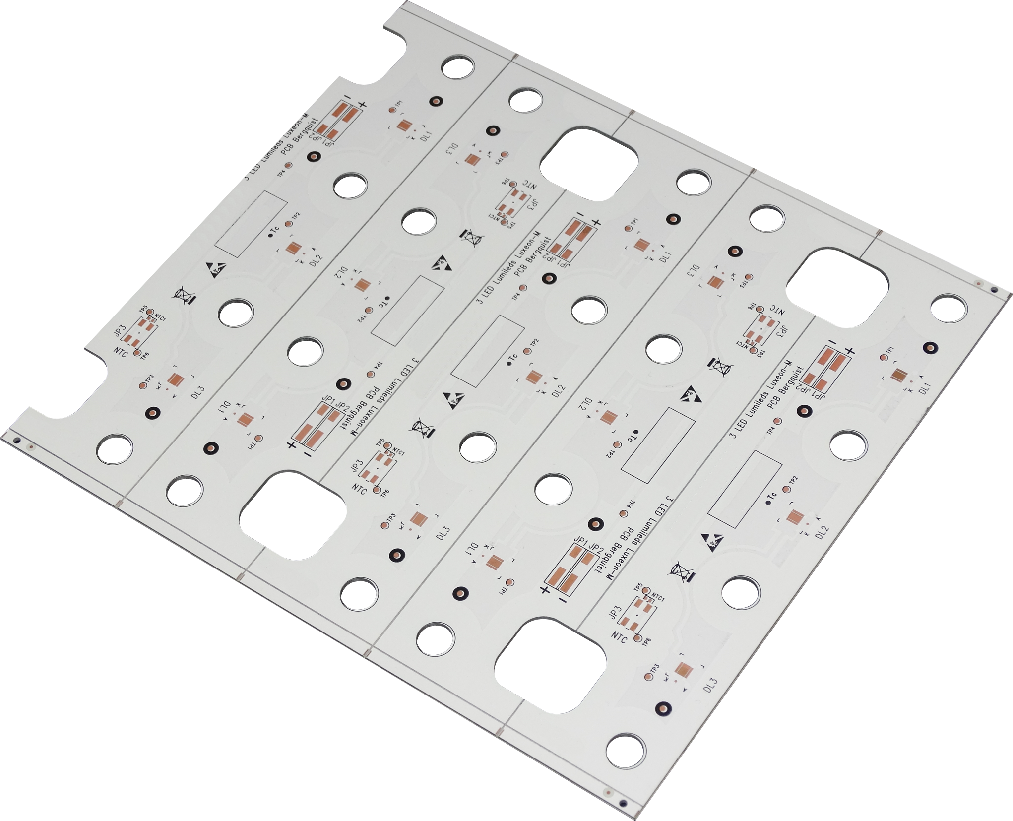
      STM32H7B3I DK, What Does STM32H7B3I-DK Mean?

      What Is the Functional Category of the STM32H7B3I-DK Development Kit?

      The STM32H7B3I-DK belongs to the STM32 Discovery Kit family, known for combining evaluation and prototyping tools in one board. It’s based on the STM32H7B3LIH6Q MCU, a high-performance 32-bit ARM Cortex-M7 core running at up to 280 MHz. The kit comes with embedded LCD, camera, and audio peripherals. It also supports external memory and has onboard sensors for easy testing. In short, it works as a complete embedded platform.

      What Is the Functional Category of the STM32H7B3I-DK Development Kit?

      What’s STM32H7B3I DK Good for in the PCB Industry?

      In the PCB field, time and precision matter. The STM32H7B3I-DK helps engineers and designers validate signal flow, power management, and firmware interactions. It’s often used for touchscreen GUI testing with TouchGFX and LVGL. Many PCB designers also use it for ‌signal validation in mid-speed multi-layer designs‌. Thanks to its ‌onboard debugger and straightforward connectivity‌, it’s ideal for checking software and hardware performance together.

      Which PCB Types Need STM32H7B3I-DK Validation Most?

      This kit is often used with ‌digital control system PCBs‌, ‌embedded HMI interfaces‌, and ‌4-8 layer multi-layer boards‌ where real-time processing and graphical rendering are needed. It’s optimized for applications involving ‌touch interfaces‌, ‌external displays‌, or ‌wired communication protocols‌. Its support for ‌MIPI-DSI displays‌ and ‌Ethernet‌ makes it valuable for industrial control panels, medical devices, and consumer electronics prototypes.

      Which PCB Types Need STM32H7B3I-DK Validation Most?

      What Are the Advantages of STM32H7B3I DK?

      There are several practical advantages to this discovery kit:

      • High-speed processing with Cortex-M7
      • Pre-mounted LCD and camera ‌connector‌ for instant GUI testing
      • TouchGFX support for interactive screen development
      • LVGL compatibility for flexible interface design
      • Built-in debugging and tracing features
      • Expandable with Arduino and STMod+ connectors
      • ‌Interface for‌ Wi-Fi ‌module‌ and low-power management

      These features give users the freedom to test, tweak, and confirm their PCB layout and function in real time.

      Where to Download STM32H7B3I-DK Schematic, Datasheet, and User Manual?

      For technical development, you’ll need accurate and up-to-date documentation. Here’s where to find everything you need:

      1. STM32H7B3I-DK Schematic: Available on the STMicroelectronics official site. It shows the circuit layout and component mapping.
      2. STM32H7B3I DK Datasheet: This gives you electrical details, memory specs, and MCU architecture.
      3. STM32H7B3I DK User Manual: Offers step-by-step instructions on using peripherals, loading code, and connecting displays or networks.

      Make sure you use the latest version to avoid any confusion. Bookmark the ST site or set up alerts for updates.

      How to Use STM32H7B3I-DK with TouchGFX or LVGL?

      TouchGFX and LVGL help developers build attractive and responsive interfaces. With STM32H7B3I-DK, you can prototype touchscreen applications right away. Simply use the onboard LCD, load the TouchGFX Designer project, and deploy it using STM32CubeIDE. If you prefer open-source, LVGL gives flexibility to create rich graphics with minimal CPU load. This board supports both options well, making it a strong choice for HMI development.

      How to Use STM32H7B3I-DK with TouchGFX or LVGL?

      All in all, the STM32H7B3I DK is more than just a development board. It’s a practical tool to speed up embedded design, validate multi-layer PCBs, and explore new applications with advanced GUIs. From industrial control to smart displays, this kit adds value at every stage. If you are planning a fast prototype or a detailed layout test, STM32H7B3I DK is ready to support you. Best Technology has been a turnkey EMS PCB manufacturer since 2006. If any questions or new PCBA project inquiries, reach out to our team via sales@bestpcbs.com.

      Bare PCB Manufacturing & Manufacturer, Over 18 Years
      Friday, June 27th, 2025

      Struggling with bare PCB manufacturing delays, hidden costs, or quality inconsistencies?‌ This guide reveals from process optimization to vendor selection, helping you achieve reliable, cost-effective boards with full traceability.

      Best Technology delivers precision-engineered bare PCBs with unmatched speed and reliability.‌ Our advanced manufacturing capabilities support 2-36 layer boards with tight tolerances (±3% impedance control, 3/3mil trace/spacing), backed by ‌100% electrical testing‌ and ‌free DFM analysis‌ to eliminate costly errors. We offer ‌24-hour rapid sampling‌ with a 99.2% on-time delivery rate—50% faster than industry averages. Unlike suppliers with hidden fees, we provide ‌transparent pricing‌ (verified by 1,200+ clients in 2024) and dedicated 1-on-1 engineering support to optimize your designs for cost-efficiency.

      With ISO-9001 and IATF 16949 certified production lines, we reduce defects to <0.5% versus the 2-3% industry standard. Whether you require HDI, rigid-flex, or high-frequency boards, our ‌24/7 responsive team‌ ensures seamless transitions from design to mass production. Let’s discuss how our ‌quality-first approach, accelerated timelines, and fair pricing‌ can streamline your PCB supply chain. Contact us now: sales@bestpcbs.com.

      What Is Bare PCB?

      A bare PCB (Printed Circuit Board) refers to the unfinished foundational board that mechanically supports and electrically connects electronic components using conductive pathways, tracks, or signal traces etched from copper sheets. Unlike assembled PCBs, these lack soldered components, conformal coating, or final finishes, essentially serving as the raw platform for subsequent manufacturing stages.
      Manufactured through processes like imaging, etching, drilling, and plating, bare PCBs vary from single-layer designs to complex multilayered structures with blind/buried vias. Their quality directly impacts end-product reliability, with factors like material selection (FR-4, Rogers, or metal-core), trace precision, and impedance control determining performance in applications ranging from consumer electronics to aerospace systems.

      What Is Bare PCB?

      What Is Bare PCB Manufacturing Process?

      Here’s a structured breakdown of the bare PCB manufacturing process, written for practical reference without promotional language:

      1. Design & File Preparation‌

      • Engineers finalize schematics and convert them into Gerber/ODB++ files, including drill maps and layer alignment data.

      2. Material Selection‌

      • Substrates (FR-4, Rogers, etc.) are chosen based on thermal, mechanical, and electrical requirements.

      3. Inner Layer Imaging‌

      • Copper-clad laminates are coated with photoresist, exposed to UV light through the design pattern, and etched to form conductive traces.

      4. Oxidation & Lamination‌

      • Inner layers are oxidized for adhesion, stacked with prepreg, and pressed under heat to create multilayer boards.

      5. Drilling‌

      • Precision CNC machines drill holes for vias and component leads, with tolerances as tight as ±0.05mm.

      6. Plating & Metallization‌

      • Holes are electroplated with copper to establish electrical connections between layers.

      7. Outer Layer Patterning‌

      • Similar to inner layers, outer copper is etched to finalize surface circuitry, often with added solder mask alignment.

      8. Solder Mask Application‌

      • A protective epoxy layer is applied, leaving only solderable areas exposed, then cured under UV.

      9. Surface Finishing‌

      • ENIG, HASL, or OSP coatings are added to prevent oxidation and ensure solderability.

      10. Electrical Testing & Inspection‌

      • Automated testing (e.g., flying probe) checks continuity, while AOI machines verify dimensional accuracy.

      11. Panelization & Scoring‌

      • Multiple PCBs are separated from production panels via V-cut or routing, ready for assembly.

      12. Final Quality Assurance‌

      • Cross-sectional analysis, impedance testing (for high-speed designs), and microsectioning validate reliability.
      What Is Bare PCB Manufacturing Process?

      What Are Common Issues of Bare PCB Board Manufacturing?

      Common issues of bare PCB board manufacturing:

      Material Incompatibility

      Issue: Using laminates unsuitable for thermal demands (e.g., lead-free soldering) causes delamination or warpage.

      Impact: Weakens board integrity, risking failures in high-temperature applications like automotive engine controls.

      Solution:

      • Material Database: Veteran manufacturers maintain a library of 50+ laminates (e.g., FR-4, Rogers 4350B) matched to thermal profiles.
      • Testing: Simulate soldering cycles (e.g., 260°C for 10 seconds) to validate material stability pre-production.
      • Benefit: Avoids $15,000+ rework costs from field failures.

        Drilling Accuracy Errors

        Issue: Mechanical drill bit deflection misaligns vias, disrupting layer-to-layer connectivity.

        Impact: Causes intermittent opens or shorts in multi-layer boards (e.g., 8+ layers).

        Solution:

          • Laser Drilling: Achieves ±20”m accuracy for microvias <75”m diameter.
          • X-ray Inspection: Verifies via placement in buried/blind via structures.
          • Benefit: Reduces re-spin rates by 60% in HDI designs.

          Inconsistent Electroplating

          Issue: Uneven copper thickness in via barrels weakens joints, risking cracks under thermal stress.

          Impact: Leads to via failure in power integrity-sensitive designs (e.g., server motherboards).

          Solution:

          • Pulse Plating: Ensures uniform 18–25”m copper deposition.
          • Cross-Section Analysis: Validates plating quality at 50+ points per panel.
          • Benefit: Improves via reliability by 4x in thermal cycling tests.

            Over-Etching

            Issue: Excessive chemical etching undercuts traces, reducing current-carrying capacity.

            Impact: Causes signal degradation in high-speed traces (e.g., USB 3.2 Gen 2×2).

            Solution:

              • Automated Etchers: Monitor etchant concentration in real-time, holding line width tolerance to ±10%.
              • Etch Factor Control: Maintains 2:1 trace-to-space ratio for 50Ω impedance traces.
              • Benefit: Preserves signal integrity in 112 Gbps SerDes applications.

              Solder Mask Misregistration

              Issue: Misaligned solder mask exposes pads, leading to solder bridges during assembly.

              Impact: Increases defect rates in fine-pitch components (e.g., 0.3mm BGAs).

              Solution:

              • Laser Direct Imaging (LDI): Achieves 15”m registration accuracy.
              • Solder Mask Dam Design: Adds 75”m dams between pads to prevent bridging.
              • Client Benefit: Reduces assembly rework by 75% in SMT lines.

              Incomplete Surface Finish

              Issue: Skipped ENIG plating steps leave copper exposed, risking oxidation.

              Impact: Causes non-wetting defects in RoHS-compliant soldering.

              Solution:

                • X-Ray Fluorescence (XRF): Verifies 0.05–0.15”m gold thickness.
                • Nickel Corrosion Testing: Exposes panels to 85°C/85% RH for 168 hours to validate adhesion.
                • Client Benefit: Extends shelf life to 12+ months without tarnishing.

                Impedance Deviations

                Issue: Poor dielectric control causes 10–15% impedance variance.
                Impact: Degrades signal integrity in 5G mmWave or PCIe 5.0 designs.
                Solution:

                • Laser Interferometry: Measures dielectric constants during lamination.
                • Embedded Capacitance: Uses Dk=4.2 materials for controlled impedance in ±5% tolerance.
                • Client Benefit: Achieves <1% eye diagram closure in 56 Gbps PAM4 channels.

                What Are the Factors Affecting the Reliability of Bare PCB Manufacturing?

                Here are the primary factors impacting reliability in bare PCB manufacturing:

                • Design for Manufacturability (DFM) Compliance‌: Overlooking automated assembly requirements like board size limits, panelization efficiency, or trace/spacing rules leads to rejection, manual handling, extended cycles, and higher costs.
                • Material Properties‌: Substrate thermal expansion coefficient mismatch with components induces stress cracks during thermal cycling. Copper foil roughness directly increases signal loss, especially at high frequencies, while inadequate thermal conductivity causes localized overheating.
                • Fabrication Process Control‌: Inconsistent etching causes undercuts or shorts. Drill misalignment or smear creates unreliable vias. Poor plating uniformity (thin spots, voids) weakens interconnects and increases resistance.
                • Impedance Control Accuracy‌: Variations in dielectric thickness, copper roughness, and trace geometry distort signals in high-speed designs, causing timing errors or data corruption.
                • Multilayer Lamination Quality‌: Layer misalignment during bonding breaks connectivity. Inadequate resin fill or voids between layers create delamination sites under thermal stress.
                • Thermal Management Design‌: High power density combined with limited copper thickness and thin substrates creates hotspots, accelerating component failure and board warpage.
                • Moisture and Contamination Resistance‌: Absorbed humidity vaporizes during soldering, causing internal blistering or layer separation. Chemical residues or pollutants corrode copper traces over time.
                • Surface Finish Integrity‌: Oxidation or poor solderability of finishes (e.g., ENIG, HASL) results in weak solder joints (voids, cold solder) prone to cracking. Inconsistent thickness reduces shelf life.
                What Are the Factors Affecting the Reliability of Bare PCB Manufacturing?

                How to Choose A Trusted Bare PCB Manufacturer?

                Below are tips to help you evaluate bare PCB manufacturer objectively:

                Prioritize Quality Over Price

                  • Certifications: Check for IPC-6012 Class 3 (aerospace/medical) and ISO 9001/IATF 16949 compliance.
                  • Testing Rigors: Ensure they perform microsectioning, thermal cycling (-55°C to +150°C), and HAST (highly accelerated stress testing) in-house.
                  • Defect Rates: Target suppliers with <0.2% scrap rates and 99.5%+ first-pass yield in SMT assembly.

                  Assess Technical Capabilities

                  • Laser Drilling: Critical for microvias <75”m diameter.
                  • Impedance Control: Look for ±5% tolerance via laser interferometry and embedded capacitance materials.
                  • Surface Finish: Verify ENIG/ENEPIG expertise for fine-pitch components (e.g., 0.3mm BGAs).

                  Verify Supply Chain Resilience

                  • Dual Sourcing: Confirm they stock laminates (e.g., FR-4, Rogers 4350B) from multiple vendors.
                  • Inventory Management: Ask about 6-month copper foil and solder dross reserves.
                  • Lead Time: Request quotes with and without material surcharges during shortages.

                  Demand Design for Manufacturing (DFM) Support

                    • 48-Hour Feedback: On trace/space, via aspect ratios, and solder mask dams.
                    • Panelization Optimization: Maximize yield while minimizing stress during depanelization.
                    • Red Flag: Suppliers charging extra for DFM or taking >72 hours to respond.

                    Evaluate Pricing Transparency

                      • Line-Item Quotes: Break down material, labor, tooling, and testing costs.
                      • Volume Discounts: Negotiate 5–15% savings for 12-month forecasts.
                      • Avoid: Bids <20% below market average (likely cuts corners on plating or QA).

                      Inspect Production Flexibility

                      • Quick-Turn Prototypes: 3–5 day lead times for 2–4 layer boards.
                      • Scalability: Capacity to handle 1–100,000+ panels without quality drift.
                      • Red Flag: Suppliers refusing to adjust line configurations for urgent orders.

                      Audit Customer Service & Communication

                        • Delays in DFM feedback or RMA requests.
                        • No dedicated project manager for your account.
                        • Unclear escalation paths for quality disputes.
                        How to Choose A Trusted Bare PCB Manufacturer?

                        How Can Ensure Fast Delivery of Bare PCB Boards Without Compromising Quality?

                        Streamline DFM (Design for Manufacturing) Reviews

                        • Submit Gerber/ODB++ files for pre-production DFM analysis within 24 hours.
                        • Prioritize fixes for acid traps, insufficient annular rings, or unbalanced copper distribution first.
                        • Why: Reduces re-spin cycles by 40% and cuts lead times by 7–10 days.

                        Leverage Automated Production Lines

                        • Laser Direct Imaging (LDI): Eliminates phototools, cutting imaging time by 50%.
                        • Automated Optical Inspection (AOI): Reduces QA cycles by 30% via AI-driven defect detection.
                        • Why: Shaves 5–8 days off standard 10–14 day lead times.

                        Optimize Material Inventory

                        • Partner with manufacturers holding 4–6 weeks of FR-4, copper foil, and solder mask stock.
                        • Use industry-standard laminates (e.g., IS410, Nelco N7000) to avoid exotic material lead times.
                        • Why: Avoids 7–10 day delays during peak demand periods.

                        Adopt Quick-Turn Prototyping

                        • Request dedicated quick-turn lines for 2–6 layer boards (3–5 day delivery).
                        • Use panelized designs to share setup costs between prototypes and production runs.
                        • Why: Accelerates NPI (New Product Introduction) by 2–3 weeks.

                        Implement Parallel Testing

                        • Conduct impedance, thermal cycling, and solderability tests concurrently.
                        • Use in-line SPC (Statistical Process Control) to monitor etching/plating in real time.
                        • Why: Reduces final QA time by 40% without quality compromise.

                        Prioritize Supplier Communication

                        • Share 12-week demand forecasts for core products.
                        • Use cloud-based portals for real-time order tracking and documentation (e.g., FAI, COC).
                        • Why: Minimizes back-and-forth and reduces order acknowledgment time to <24 hours.

                        Utilize Express Shipping for Critical Components

                        • Pre-book air freight for time-sensitive boards.
                        • Use regional manufacturers (e.g., Asia for APAC clients) to cut transit times.
                        • Why: Shaves 50% off shipping lead times for urgent orders.

                        How to Reduce Bare PCB Manufacturing Costs While Maintaining High Performance?

                        Below are actionable strategies to cut expenses without compromising reliability:

                        Optimize Material Selection

                        • Use industry-standard laminates (e.g., FR-4, IS410) instead of specialty materials unless required by thermal/electrical demands.
                        • Negotiate volume discounts for copper foils and solder masks with suppliers.
                        • Cost Saving: Reduces material expenses by 10–15% for standard designs.

                        Adopt Design for Manufacturing (DFM) Best Practices

                        • Standardize trace/space to 4mil (100”m) and via diameters to 0.2mm to avoid costly microvia processes.
                        • Use panelization to improve material utilization from 75% to >90%.
                        • Cost Saving: Cuts PCB costs by 20–30% through reduced scrap and simpler tooling.

                        Leverage Automated Production Lines

                        • Deploy Laser Direct Imaging (LDI) to eliminate phototool costs (150–300 per layer).
                        • Use AOI (Automated Optical Inspection) to reduce manual QA labor by 40%.
                        • Cost Saving: Lowers per-unit labor costs by 25–35%.

                        Streamline Testing Protocols

                        • Replace 100% electrical testing with flying probe sampling for low-risk designs.
                        • Use in-line SPC (Statistical Process Control) to monitor etching/plating in real time
                        • Cost Saving: Reduces testing expenses by 15–20% without quality compromise.

                        Consolidate Suppliers for Volume Discounts

                        • Partner with manufacturers offering tiered pricing for 12-month forecasts.
                        • Use regional suppliers to cut logistics costs (e.g., Asia for APAC clients).
                        • Cost Saving: Achieves 5–10% savings through bulk orders and reduced shipping.

                        Implement Just-in-Time (JIT) Inventory

                        • Sync production schedules with client demand forecasts to minimize stockpiling.
                        • Use Kanban systems to reorder materials only when needed.
                        • Cost Saving: Reduces working capital tied to inventory by 30–40%.

                        Reuse Engineering Change Orders (ECOs)

                        • Template common ECOs (e.g., trace widening, pad resizing) for faster approvals.
                        • Avoid ECOs during peak hours to prevent production line interruptions.
                        • Cost Saving: Lowers engineering overhead by 25–35%.

                          How Can Manufacturer Improve the Traceability of Bare PCB Production?

                          Implement Digital Thread Systems

                          • Use IoT sensors and barcode scanning to track panels through drilling, plating, etching, and testing.
                          • Link Gerber files, BOMs, and process parameters to unique serial numbers.
                          • Benefit: Enables real-time audits of material lots and machine settings.

                          Adopt Laser-Etched Serialization

                          • Engrave QR codes or Data Matrix symbols on boards during inner layer imaging.
                          • Ensure codes survive solder mask, HASL, or ENIG finishes.
                          • Benefit: Simplifies recalls by pinpointing affected boards in <1 hour.

                          Integrate MES (Manufacturing Execution Systems)

                          • Auto-capture data from AOI, flying probe testers, and thermal chambers.
                          • Generate digital “birth certificates” with SPC charts and inspection images.
                          • Benefit: Reduces audit preparation time by 70%.

                          Standardize Material Lot Tracking

                          • Record laminate batch numbers, copper foil rolls, and solder mask expiry dates.
                          • Flag lots approaching shelf life during DFM reviews.
                          • Benefit: Avoids defects from degraded materials in 95% of cases.

                          Leverage Blockchain for Supply Chain Transparency

                          • Create immutable records of material origins, certifications, and ESG compliance.
                          • Share hashes with clients for independent verification.
                          • Benefit: Strengthens trust in conflict-free minerals and RoHS compliance.

                          Automate Data Collection at Every Step

                          • Use edge computing to log etchant concentrations, plating currents, and oven temperatures.
                          • Trigger alerts for OOT (out-of-tolerance) conditions.
                          • Benefit: Reduces human error in data entry by 90%.

                          Conduct Regular Calibration Audits

                          • Certify machines (e.g., drill spindles, etching tanks) monthly using NIST-traceable standards.
                          • Store calibration records in cloud repositories.
                          • Benefit: Maintains ±5% measurement accuracy across tools.

                          Train Operators on Traceability Protocols

                          • Require daily scans of material reels and tooling IDs.
                          • Gamify compliance with leaderboards and performance bonuses.
                          • Benefit: Achieves 99%+ scan adherence in 4–6 weeks.

                          Conclusion

                          Bare PCB manufacturing demands precision across design, material selection, and production processes to avoid impedance mismatches, etching defects, and layer misalignment. Best Technology delivers reliable solutions with 18+ years of expertise, combining ‌free DFM analysis‌ to prevent 90% of pre-production errors and ‌automated traceability systems‌ for real-time quality tracking. Our ‌vertically integrated supply chain‌ reduces costs by 15-30% while maintaining IPC Class 3 standards, supported by a ‌24-hour engineering team‌ to accelerate delivery without quality compromise. For high-performance bare PCBs with guaranteed signal integrity and on-time delivery, request your competitive quote today at sales@bestpcbs.com.

                          Basic Electron Devices and Circuits
                          Friday, June 27th, 2025

                          Electron devices and circuits are the foundation of modern electronics. From smartphones and computers to medical scanners and satellite systems, these components quietly manage the flow of electricity behind the scenes. This blog explores how they work, what types exist, and how they power the electronic world around us.

                          Basic Electron Devices and Circuits

                          What Are Electron Devices?

                          Electron devices are components that either control, modify, or amplify electrical signals. These devices rely on the movement of electrons to function and are used in countless applications, from simple toys to complex industrial machinery. Their job is to manage electrical energy in ways that produce useful output—such as turning on lights, processing data, or amplifying sound.

                          At their core, electron devices convert electrical energy into other forms or modify electrical signals to perform a specific function. Without them, modern electronic systems wouldn’t be possible.

                          Types of Electronic Devices

                          Each electronic component has specific properties that determine how it behaves in a circuit. The choice of components depends on the designer’s goal and the function the circuit is meant to perform. The image below highlights common electronic components used across various types of circuits. To better understand their roles, components are generally classified into two categories: Active Components and Passive Components.

                          1. Active Devices

                            Active devices can control current flow and even amplify weak electrical signals. These devices require an external power source to operate. Some common active devices include:

                            • Transistors: Used in amplifiers and switches.
                            • Diodes: Let current flow in one direction.
                            • Integrated Circuits (ICs): Tiny packages that contain complex electronic functions.

                            Active devices are central to any system that processes signals, computes information, or boosts communication signals.

                            2. Passive Devices

                            Passive devices do not generate energy. Instead, they store, dissipate, or transfer it. Common examples include:

                            • Resistors: Limit the flow of current.
                            • Capacitors: Store and release electrical energy.
                            • Inductors: Resist sudden changes in current.
                            Types of Electronic Devices

                            These components support the work of active devices and help shape how signals behave in a circuit.

                            What Are the 5 Basic Electronic Devices?

                            The five basic devices you’ll find in nearly every circuit are:

                            • Resistor

                            Resistors manage the current flowing through different parts of a circuit. They help in dividing voltage, controlling signal levels, and protecting components from excessive current.

                            • Capacitor

                            Capacitors store electrical charge temporarily. They’re used in filtering noise, smoothing power supply outputs, and creating time delays.

                            • Inductor

                            Inductors store energy in a magnetic field when current flows through them. They’re commonly used in filters, power supplies, and transformers.

                            • Diode

                            Diodes allow current to flow in only one direction. They are essential in power rectification, signal demodulation, and voltage regulation.

                            • Transistor

                            Transistors act as switches or amplifiers. They control the flow of current and are fundamental to logic circuits and digital electronics.

                            How Do Electronic Devices Work?

                            Each electronic device has a specific function based on its physical and electrical characteristics:

                            • Resistors slow down current.
                            • Capacitors store energy in an electric field.
                            • Inductors build magnetic fields.
                            • Diodes control direction.
                            • Transistors regulate and amplify signals.

                            Together, these devices shape how electricity behaves inside a circuit. When connected in specific arrangements, they form circuits capable of performing tasks like amplifying a sound, storing digital information, or controlling a motor.

                            How Do Electronic Devices Work?

                            What Are Electronic Circuits?

                            An electronic circuit is a system of connected components that guide electrical currents to perform a specific job. These circuits can be as simple as a battery lighting an LED or as complex as the logic boards inside a computer.

                            Circuits make electronic devices work by controlling where and how electricity flows. Each component in the circuit has a role—some store energy, others shape signals, and some respond to external inputs like light or sound.

                            Types of Electronic Circuits

                            Electronic circuits come in a few major types, depending on how they handle signals:

                            • Analog Circuits

                            Analog circuits work with continuous signals. They are used in audio systems, radio receivers, and temperature sensors. They process real-world inputs like sound or light.

                            • Digital Circuits

                            Digital circuits work with binary signals (0s and 1s). They form the backbone of computers, smartphones, and digital watches. Logic gates and microcontrollers are key components.

                            • Mixed-Signal Circuits

                            These combine analog and digital elements. Examples include digital audio converters, embedded controllers, and power management circuits.

                            Types of Electronic Circuits

                            Key Components in Electronics Circuits

                            A functioning circuit depends on a combination of components, each with a distinct role:

                            • Power Supply: Provides the necessary voltage and current.
                            • Resistors: Manage current flow and protect sensitive parts.
                            • Capacitors & Inductors: Shape or filter signals and manage timing.
                            • Diodes & Transistors: Control signal direction, switching, and amplification.
                            • Integrated Circuits (ICs): Combine multiple components in one small package for complex functions.
                            • Switches, Connectors & PCBs: Physically support and route current throughout the system.

                            All these parts are arranged on a printed circuit board (PCB), which provides the mechanical structure and electrical connections.

                            Key Components in Electronics Circuits

                            How to Design an Electronic Circuit?

                            Designing a circuit starts with a clear goal. Once the purpose is defined, follow these steps:

                            1. Outline Your Requirements: What do you want the circuit to do?
                            2. Create a Schematic: Use circuit design software to build the layout using symbols for each component.
                            3. Select Components: Choose values for resistors, capacitors, etc., based on your requirements.
                            4. Simulate the Circuit: Check how it behaves using tools like LTspice or Proteus.
                            5. Build a Prototype: Use a breadboard or PCB to assemble and test your design.
                            6. Test & Debug: Measure voltages and currents to confirm it works as expected.
                            7. Final Layout: Once tested, you can design a PCB for the final version.

                            Even simple circuits need careful planning, as incorrect wiring or value choices can lead to failure or inefficiency.

                            Common Measurement Devices for Electronic Circuits

                            To check and troubleshoot circuits, engineers use various tools:

                            • Multimeter: Measures voltage, current, and resistance. Essential for almost any testing.
                            • Oscilloscope: Displays how signals change over time—helpful for analyzing waveforms.
                            • LCR Meter: Measures inductance (L), capacitance (C), and resistance (R).
                            • Logic Analyzer: Helps in debugging digital signals and timing issues.

                            These devices ensure that the circuit performs properly under different conditions.

                            Applications of Electron Devices and Circuits

                            Electron devices and circuits power virtually all technology we use today. Here are a few major application areas:

                            • Consumer Electronics: Televisions, phones, game consoles, and home appliances all rely on sophisticated circuits.
                            • Automotive Systems: Used in engine control units (ECUs), ABS brakes, GPS modules, and more.
                            • Medical Devices: Circuits manage everything from heart monitors to imaging systems.
                            • Telecommunications: Signal boosters, routers, and network devices depend on electronic components.
                            • Industrial Equipment: Used in automation, robotics, and machine control systems.
                            • Defense & Aerospace: Critical in radar systems, flight control computers, and satellite communications.

                            No matter the industry, the role of electron devices and circuits is critical in innovation, performance, and safety. Whether you’re a student, hobbyist, or professional, grasping how circuits function and how devices interact is essential to designing or repairing electronic equipment.

                            For those looking to build reliable circuit boards or need help bringing their electronic designs to life, partnering with an expert manufacturer is key.

                            Why Choose Best Technology for Electronic Circuit Projects?

                            Best Technology is a trusted PCB manufacturer specializing in both prototype and volume production. With ISO-certifications, our team ensures your circuits meet international standards. Whether you need rigid PCBs, flexible circuits, or mixed-signal board assemblies, we help turn your ideas into high-quality products—on time and within budget. By choosing Best Technology, you can enjoy:

                            1. Fast Turnaround from Prototype to Mass Production

                            We help you move quickly from design to final product. Whether it’s a first-run prototype or a full production batch, we adapt to your schedule and keep your project on track.

                            2. Hands-On Engineering Support

                            Our experienced engineers work with you on component selection, stack-up optimization, and layout suggestions—helping you avoid design flaws before production begins.

                            3. High Customization, No Fear of Complexity

                            Need a non-standard stack-up, hybrid materials, or bendable structures? We handle complex builds with confidence and tailor every detail to match your design requirements.

                            4. Clear Quotes and On-Time Delivery

                            Our pricing is transparent, and our timelines are realistic. Dedicated project coordinators provide regular updates, so you’re never left guessing.

                            5. Quality is a Daily Practice, Not Just a Promise

                            We don’t just inspect a few boards—we test every unit. From flying probe tests to X-ray and AOI, our quality process ensures every board performs reliably.

                            FAQs

                            1. What’s the difference between an electronic and electrical device?

                            Electronic devices use the flow of electrons to process signals, while electrical devices typically handle power distribution and energy conversion.

                            2. Can I build electronic circuits without a PCB?

                            Yes, prototypes are often built on breadboards or perfboards, but PCBs are used for stability and durability in final products.

                            3. What software is best for circuit design?

                            Popular tools include KiCad, Eagle, Altium Designer, and Proteus for simulation and layout.

                            4. What is the most common cause of circuit failure?

                            Overheating, poor soldering, incorrect component values, or voltage surges are common failure causes.

                            5. How do I start learning electronics as a beginner?

                            Start with basic components, build simple circuits using breadboards, and gradually move to microcontroller projects using kits like Arduino or Raspberry Pi.

                            Circuit Board Generator For PCB Design
                            Friday, June 27th, 2025

                            Seeking for circuit board generator for your design? This guide covers automated pattern/font generation, error reduction, and signal integrity optimization, helping you save time and costs at every stage.

                            Best Technology stands out as your ideal PCB design partner with tangible benefits that accelerate your projects. We provide ‌free DFM analysis‌ with every design to prevent costly manufacturing errors upfront. Our pricing is ‌transparent and competitive‌ with no hidden charges. When you need support, our ‌24-hour response team‌ delivers solutions faster than industry standards. What truly differentiates us is our ‌dedicated designer team‌ offering real-time 1-on-1 consultations to address your specific challenges.

                            With 18+ years of specialized experience, we’ve optimized our circuit board generators to handle complex multilayer designs while maintaining 99.2% first-pass success rates. Let us prove how our combination of ‌technical expertise, cost efficiency and responsive service‌ can streamline your PCB development – contact us today for a risk-free consultation: sales@bestpcbs.com.

                            What Is a Circuit Board Generator?

                            A circuit board generator is a specialized system that translates electronic circuit designs into functional printed circuit boards (PCBs). It bridges the gap between schematic diagrams and physical hardware.

                            Software circuit board generators automate PCB layout creation. They handle component positioning, copper trace routing according to electrical requirements, and manufacturability checks. These tools produce essential industry-standard output files like Gerber formats, accelerating development for complex designs such as multi-layer boards or high-frequency circuits.

                            Physical circuit board generators directly create prototype boards using methods like milling, etching, or additive printing. This enables tangible board production within hours for rapid testing. Specialized versions also exist for creating custom silkscreen markings, electromagnetic shielding patterns, or experimental circuit configurations.

                            By efficiently translating electronic concepts into manufacturable realities, circuit board generators streamline the entire development cycle, ensuring designs meet fabrication standards while dramatically shortening prototyping time.

                            What Is a Circuit Board Generator?

                            What Are Software For Circuit Board Generator?

                            Here are software tools for circuit board generator:

                            • Schematic Capture Interface:‌ This foundational tool allows designers to create the logical diagram of the circuit using standardized electronic symbols. It precisely defines component connections, establishing the functional blueprint before physical layout begins.
                            • Component Library Manager:‌ Comprehensive libraries store detailed information on parts, including schematic symbols, physical footprints (pad shapes, sizes), 3D models, and electrical parameters. This prevents errors and streamlines component selection and placement.
                            • Placement Assistance:‌ Tools provide visual cues and automated suggestions for positioning components on the board layout. Designers maintain control while benefiting from optimized arrangements that minimize trace lengths and consider thermal or signal constraints.
                            • Interactive Routing Engine:‌ This facilitates creating physical copper connections (“traces”) between component pins, offering manual, semi-automated, or fully automated modes. Intelligent routing adheres to spacing rules, manages complex paths (like differential pairs), and ensures signal integrity.
                            • Real-time Design Rule Checker (DRC):‌ Operating continuously, this enforces user-defined and fabrication constraints (trace width, spacing, hole sizes). Immediate feedback on violations prevents costly errors reaching manufacturing.
                            • Manufacturing File Generator:‌ Upon successful verification, the system automatically exports industry-standard files essential for production, including Gerber files (copper layers, solder mask, silkscreen) and drill files (Excellon format).
                            • Signal Integrity Analyzer:‌ Integrated simulation tools model how electrical signals behave on traces. This helps predict and mitigate issues like noise, reflections, or timing errors before prototyping, enhancing reliability.
                            • Power Integrity Analysis Tool:‌ Dedicated features analyze voltage stability and current distribution across the board, identifying potential drops or excessive noise that could impact circuit performance.
                            • 3D Visualization & Mechanical Integration:‌ Tools render the board and components in 3D, enabling collision checks with enclosures or other mechanical parts. This ensures physical fit and compatibility early in the design cycle.
                            • Bill of Materials (BOM) Generator:‌ Automatically extracts a complete list of all required components directly from the design data, simplifying procurement, cost estimation, and assembly preparation.
                            • Version Control & Data Management:‌ Integrated systems track design revisions, manage project files, and support collaborative workflows, safeguarding progress and enabling efficient team coordination.
                            • CAM Processor Interface:‌ While distinct from the generator core, robust interfaces allow seamless data transfer to specialized CAM (Computer-Aided Manufacturing) software for final fabrication preparation and panelization. This ensures smooth handoff to manufacturing partners.

                            What Are Function of Circuit Board Generator?

                            Function of circuit board generator:

                            • Translating Schematics into Physical Layouts: The circuit board generator converts logical circuit diagrams into precise, manufacturable board geometries. This ensures the electrical connections defined in the schematic are accurately reflected in the physical copper pathways and component placement.
                            • Managing Comprehensive Component Libraries: It centrally stores and organizes detailed information for every part used. This includes schematic symbols, footprints (defining physical pad layouts and outlines), 3D models, and electrical parameters, guaranteeing consistency and preventing placement or assembly errors.
                            • Facilitating Intelligent Component Placement: While designing, the circuit board generator provides visual aids and automated suggestions based on connectivity and design rules. This assists in arranging components efficiently, minimizing trace lengths for better signal performance, managing heat distribution, and respecting mechanical constraints.
                            • Enabling Rule-Driven Routing: The generator offers powerful tools for creating the copper traces connecting components. Designers can route manually, use guided assistance, or employ automation – all while strictly adhering to spacing rules, managing impedance for sensitive signals, and avoiding electrical conflicts.
                            • Enforcing Real-Time Design Rules: Continuously, the circuit board generator checks the layout against predefined manufacturing tolerances (trace width, spacing, hole sizes) and electrical requirements. Immediate feedback on violations prevents costly errors from reaching fabrication, saving significant time and money.
                            • Generating Essential Manufacturing Files: Upon design completion and verification, the circuit board generator automatically exports the complete set of industry-standard files required for production. These include Gerber files for each copper layer, solder mask, and silkscreen; Excellon drill files; assembly drawings; and accurate Bills of Materials (BOM).
                            • Supporting Early Electrical Verification: Through integrated simulation, the circuit board generator allows designers to analyze signal behavior and power distribution stability before physical prototypes exist. Identifying potential issues like noise or voltage drops at this stage significantly reduces later development risks and costs.
                            • Producing Functional Prototypes: When connected to compatible milling or printing equipment, the circuit board generator directly drives the machinery to create tangible, working prototype boards within a short timeframe. This accelerates testing and validation cycles dramatically.

                            What Are Applications of Circuit Board Generator?

                            Applications of circuit board generator:

                            • Consumer Electronics‌ – Designs compact boards for smartphones, wearables, and smart home devices
                            • Industrial Systems‌ – Creates durable control boards for factory equipment and power systems
                            • Automotive Tech‌ – Develops reliable vehicle electronics for engine control, ADAS, and EV batteries
                            • Aerospace & Defense‌ – Produces ultra-reliable boards for aircraft systems and military equipment
                            • Medical Devices‌ – Enables precise circuits for diagnostic machines and implantable devices
                            • Telecom Equipment‌ – Builds complex boards for network infrastructure and communication systems
                            • IoT Devices‌ – Designs connected sensors and smart controllers with wireless capabilities
                            • Energy Systems‌ – Creates boards for solar inverters, wind turbines, and smart grid technology
                            • Robotics‌ – Develops control circuitry for industrial robots, drones, and automated systems
                            • Education & Research‌ – Supports academic learning and rapid prototyping for new technologies

                            Why Choose a Circuit Board Pattern Generator​ for RF PCB Designs?

                            Reasons why choose a circuit board pattern generator for RF PCB designs:

                            • Save Time on Repetitive Tasks‌: Instead of manually drawing common patterns (like ground planes or RF shields), the generator automates these layouts. This means you can focus on custom parts of your design, reducing hours of work to minutes.
                            • Reduce Human Errors‌: Manual tracing risks small mistakes—misaligned vias or uneven spacing. Automated patterns ensure consistency, especially for high-frequency designs where precision matters.
                            • Test Ideas Faster‌: Quickly generate multiple pattern variations (e.g., different antenna shapes or thermal reliefs) to compare performance in simulations. Ideal for prototyping phases.
                            • Simplify Complex Geometries‌: For advanced needs like curved traces or fractal-based layouts, the tool handles math-heavy optimizations you’d otherwise calculate manually.
                            • Standardize Designs Across Teams‌: Share pre-validated patterns (e.g., EMI shields or power distribution networks) with colleagues, ensuring everyone uses the same reliable templates.
                            • Adapt to Material Constraints‌: Some generators adjust patterns based on your PCB’s dielectric properties or manufacturing limits, avoiding costly post-design fixes.
                            • Enhance Aesthetics Without Sacrificing Function‌: Create visually appealing boards (e.g., artistic logos or decorative elements) while maintaining electrical integrity—useful for consumer electronics.
                            • Lower Learning Curve for New Designers‌: Beginners can leverage pre-built patterns to understand best practices, like proper via stitching or impedance matching, without deep prior experience.
                            Why Choose a Circuit Board Pattern Generator​ for RF PCB Designs?

                            How a Circuit Board Font Generator Saves Time in Custom Marking Design?

                            Automated Font Compliance

                            • PCBs require silkscreen markings that adhere to manufacturing standards (e.g., minimum line width, spacing). Font generators automatically apply industry-compliant fonts, ensuring legibility without manual adjustments. This prevents costly reworks caused by non-conforming text.

                            Instant Customization

                            • Engineers often need to modify text for branding, part numbers, or warnings. Font generators allow real-time edits to size, style, and orientation. For example, adjusting a logo’s placement on a crowded board takes seconds, whereas manual redrawing in CAD tools could consume hours.

                            Multi-Language Support

                            • Products sold globally require PCBs with labels in multiple languages. Font generators store libraries of Unicode characters, enabling quick switching between alphabets (e.g., English, Chinese, Cyrillic) without redrawing symbols. This simplifies localization for international markets.

                            Export Efficiency

                            • Font generators output silkscreen layers in standard formats (e.g., Gerber RS-274X), ensuring compatibility with PCB fabrication software. This eliminates time-consuming file conversions or manual layer stacking in EDA tools.

                            Reduced Dependency on Graphic Designers

                            • Non-expert users can generate production-ready text without assistance. For example, a hardware engineer can independently add a company logo or safety certification marks, bypassing the back-and-forth with graphic design teams.

                            Accelerated Prototyping

                            • During iterative testing, engineers frequently update PCB labels (e.g., version numbers, test parameters). Font generators apply changes across entire board layouts in minutes, whereas manual edits risk inconsistencies and delays.

                            Cost Avoidance for Low-Volume Runs

                            • For niche products, outsourcing custom silkscreens is expensive. Font generators enable in-house design of unique markings, cutting per-unit costs by up to 30% for small batches.
                            How a Circuit Board Font Generator Saves Time in Custom Marking Design?

                            How to Avoid PCB Rework Costs With Automated Font and Pattern Generation Tools?

                            Enforce Design Rules in Real Time

                            • Automated tools apply industry standards (e.g., IPC-7351B) as you design. For example, a circuit board font generator ensures silkscreen text meets minimum line width and spacing requirements, preventing illegible markings that fail quality control. Similarly, a pattern generator flags traces violating impedance tolerances, avoiding signal reflections that require board scrapping.

                            Optimize Shielding Layouts for EMI Compliance

                            • Manual shielding designs often leave gaps or improper via stitching, leading to electromagnetic interference (EMI). A circuit board pattern generator automates the creation of continuous ground planes, via fences, and honeycomb patterns. This reduces rework caused by failed EMC testing, saving 500–2,000 per failed batch in testing and assembly costs.

                            Prevent Material-Related Errors

                            • Different PCB substrates (e.g., FR-4 vs. Rogers) affect trace impedance and thermal performance. Automated tools adjust pattern geometries based on material properties. For instance, they widen traces on high-loss materials to maintain signal integrity, avoiding costly re-spins due to unexpected signal attenuation.

                            Streamline Multi-Layer Alignment

                            • Misaligned layers in complex boards (e.g., 8+ layers) cause shorts or opens. Tools like Blender circuit board generators simulate 3D layer stacking, highlighting misregistrations before fabrication. This proactive check reduces rework rates by up to 40% in high-density interconnect (HDI) designs.

                            Automate Custom Markings for Consistency

                            • Hand-drawn logos or part numbers often vary in size or position, causing assembly errors. A circuit board font generator locks text dimensions and positions relative to components. For example, it ensures QR codes remain scannable even after multiple design iterations, avoiding line downtime due to labeling mistakes.

                            Accelerate Design-to-Fabrication Handoff

                            • Manual export of silkscreen and copper layers frequently introduces file errors (e.g., missing layers, inverted polars). Automated tools generate Gerber, ODB++, or Excellon files directly from validated designs. This cuts file-related rework by 70%, as engineers no longer troubleshoot mismatched layers.

                            Reduce Prototype Iterations

                            • A random circuit board generator helps test unconventional layouts (e.g., randomized via patterns for thermal management) digitally. Engineers identify failures in simulation rather than physical prototypes, slashing iteration cycles from weeks to days.
                            How to Avoid PCB Rework Costs With Automated Font and Pattern Generation Tools?

                            Can Random PCB Generators Improve Signal Integrity in High-Speed Multilayer Boards?

                            Here’s how random PCB generators enhance signal integrity in high speed multilayer boards:

                            Breaking Traditional Layout Constraints

                            • High-speed signals demand precise control over trace length, impedance, and coupling. Random generators experiment with non-linear routing paths that reduce parallel run lengths between aggressive and passive traces, minimizing crosstalk. For example, they might stagger differential pairs to avoid uniform spacing that amplifies interference.

                            Optimizing Via Placement for Layer Transitions

                            • Vias introduce stubs and inductance that degrade signal integrity at GHz frequencies. Random generators test thousands of via configurations to identify layouts with minimal stub lengths or backdrilled options. This trial-and-error approach uncovers solutions that deterministic algorithms might skip due to computational limits.

                            Balancing Ground Pour Density

                            • Uneven ground planes create impedance discontinuities. Random tools distribute copper pours dynamically, ensuring consistent return paths for high-speed signals. They might fill empty board areas with staggered ground vias or adjust pour shapes to match trace density, reducing loop inductance.

                            Reducing Resonance in Power Planes

                            • Parallel power/ground planes can resonate at specific frequencies, causing EMI. Random generators perturb plane geometries to disrupt resonant modes. For instance, they might add offset slots or randomize via spacing to scatter electromagnetic energy harmlessly.

                            Enhancing Thermal Dissipation Without Compromising SI

                            • High-speed designs often face thermal-signal integrity trade-offs. Random generators place thermal vias and copper fills in non-uniform patterns that avoid clustering near sensitive traces. This maintains signal integrity while preventing hotspots that could warp boards or shift component values.

                            Automated What-If Scenarios for Differential Pairs

                            • Manual tuning of differential pairs is time-consuming. Random tools simulate millions of variations in trace width, spacing, and length matching. They identify layouts where intentional skew compensates for layer-specific propagation delays, improving eye diagrams in SerDes channels.

                            Mitigating Skew in Multi-GHz Clock Networks

                            • Clock trees require tight skew control. Random generators explore non-radial routing topologies that balance delays across branches. By avoiding symmetrical “star” patterns prone to process variations, they achieve 30% lower skew in PCIe or DDR5 interfaces.

                            Validating Robustness to Manufacturing Variations

                            • High-speed boards are sensitive to etching tolerances and dielectric variations. Random generators stress-test layouts by simulating worst-case process shifts. They recommend designs where intentional trace wiggles or redundant via fences buffer against production inconsistencies.

                            Conclusion

                            Circuit board generators revolutionize PCB design by automating pattern creation, reducing errors, and enhancing efficiency. Whether you need precise silkscreen markings, optimized signal paths, or faster design iterations, these tools deliver measurable results. For reliable solutions that fit your specific project requirements, Best Technology offers customized generator tools with expert support. Contact us today for a competitive quote and take your PCB designs to the next level with professional-grade automation. Let’s discuss how we can streamline your workflow while maintaining quality standards: sales@bestpcbs.com.

                            Super Quality PCBA Manufacturer in China for Fast Delivery
                            Friday, June 27th, 2025

                            PCBA Manufacturer in China is a keyword that resonates with global buyers who demand fast, precise, and trusted electronics assembly services. If you’re looking for a reliable partner who delivers consistent quality on tight timelines, you’re not alone. The competition in electronics manufacturing is intense, and choosing the right PCBA supplier is no longer just about cost—it’s about control, speed, and support.

                            To ensure every customer enjoys super quality PCBA and satisfactory service, Best Technology offers DFA checks, rapid prototyping service, and a wide range of PCBA choices for customers, such as 4L, 6L, 8L, and 12L FR4 PCB assembly, 4L rigid-flex PCBA assembly, ceramic PCB assembly, and box building services. Best Technology is a PCBA board manufacturer for electronics in China. We promise a super-quality SMT PCBA and efficient delivery. And we will provide the best service for you. Feel free to share your BOM list, silk screen position diagram, and SMD coordinates with us at sales@bestpcbs.com, and we will be pleased to share our specific quoting correspondingly.

                            Super Quality PCBA Manufacturer in China for Fast Delivery

                            Who Is the Best PCBA Manufacturer in China?

                            Many companies call themselves top suppliers, but the best PCBA manufacturer in China goes beyond high volume. It’s about who can provide stable quality, quick turnaround, and full technical backup. Best Technology, for example, has earned the trust of global clients through a well-managed MES system, certified production (ISO9001, ISO13485, IATF16949, AS9100D), and a customer-first approach. Clients choose them not just for products—but for comprehensive solutions.

                            Who Is the Best PCBA Manufacturer in China?

                            Where Are Most PCBA Manufactured?

                            Most PCBA manufacturing in China is concentrated in regions like Shenzhen, Dongguan, and Suzhou. Shenzhen stands out as the heart of the electronics industry. With access to a robust supply chain, skilled labor, and modern logistics, PCBA China suppliers in this area offer faster prototyping and flexible batch production. That’s why many global electronics brands choose this hub for their key projects.

                            What Services Do Top PCB Assembly Manufacturers in China Offer?

                            Leading PCBA board manufacturers for electronics in China don’t just offer assembly. They provide full turnkey services—PCB fabrication, SMT, DIP soldering, functional testing, BGA rework, and conformal coating. Best Technology adds an extra layer of value through DFM feedback, component suggestions, and custom packaging. In-house AOI, X-ray, ICT, and full traceability reporting help buyers avoid quality risks and shorten development cycles.

                            What Services Do Top PCB Assembly Manufacturers in China Offer?

                            What Is the Difference Between Bare PCB and PCBA?

                            The terms sound similar but represent two different stages. A bare PCB is the raw board with only copper traces and no parts. A PCBA (Printed Circuit Board Assembly) includes all the soldered components. The jump from PCB to PCBA adds complexity and responsibility—especially in terms of inspection, process control, and final test. So, working with a skilled PCBA China team can reduce rework, returns, and missed deadlines.

                            Who Is the Manufacturer of Bare PCB in China?

                            China has countless PCB manufacturers. However, very few manage both bare board production and complete PCBA in one location. Best Technology is one of the few that offers integrated services. This helps maintain consistency between PCB and assembly quality. No more back-and-forth between multiple suppliers. Customers benefit from a single point of accountability, stronger material control, and fewer delays.

                            Who Is the Manufacturer of Bare PCB in China?

                            How to Choose a Reliable Shenzhen PCBA Manufacturer for Fast Turnaround?

                            First, check for certifications—ISO 9001, ISO 13485, IATF 16949, and others prove the factory follows international standards. Second, examine their testing process. Do they use AOI, X-ray, ICT, and FCT? Third, review their past delivery records. Finally, talk to their support team. A fast response today shows how they’ll support you tomorrow. Best Technology checks all the boxes and adds extra value with proactive DFM support and 24/7 communication. Fast delivery isn’t luck—it’s planning.

                            How to Choose a Reliable Shenzhen PCBA Manufacturer for Fast Turnaround?

                            Why Choose Best Technology for PCB & PCBA Manufacturer in China?

                            Customers choose Best Technology for a reason. Their strength lies in four pillars:

                            • Quality Control: They operate under a complete quality system—from raw material inspection to final test. Every board passes AOI and functional checks before shipping.
                            • Fast Delivery: Thanks to lean manufacturing and automated lines, urgent orders ship in as fast as 24–48 hours.
                            • Technical Support: Their engineering team works with your design to avoid issues before production starts.
                            • Customer Service: Around-the-clock response ensures you’re never left waiting.

                            Moreover, Best Technology manages orders with a clear process and always seeks continuous improvement. Whether you’re scaling up or launching a new design, they reduce your risks and help you move fast—without quality trade-offs.

                            Why Choose Best Technology for PCB & PCBA Manufacturer in China?

                            As a final point, finding the right PCBA Manufacturer in China is more than a search—it’s a strategic decision. Customers today need more than just low cost. They want accountability, speed, quality, and clear communication. Best Technology stands out with its strong engineering, fast delivery, rigorous testing, and transparent support model. In a world where missed deadlines and poor quality hurt business, choosing a trusted partner like Best Technology can make a big difference for your projects.

                            Best Technology is a super quality PCBA manufacturer in China for fast delivery. If you’re tired of delays, rework, and poor communication, it’s time to work with a supplier who delivers not just boards—but viable solutions. Please email Best Technology at sales@bestpcbs.com if you have new inquiries or would like to schedule a factory visit with us.
                            SMPS PCB Board Prototyping, Fast Delivery
                            Thursday, June 26th, 2025

                            Seeking for SMPS PCB Board solutions? This guide explores its definition, functions, applications, design strategies, and fast-delivery advantages.

                            Best Technology specializes in high-quality SMPS PCB board prototyping and assembly services with industry-leading 24-hour quick-turn delivery. Our accelerated production process ensures fast turnaround without compromising quality, supported by:

                            • Free professional DFM analysis to optimize designs for manufacturability
                            • Advanced fabrication capabilities (up to 20-layer boards, 6oz copper)
                            • Full IPC-A-600 compliant quality control with flying probe testing
                            • Mixed-technology assembly (SMT+THT) for complex power electronics

                            With 18+ years of SMPS manufacturing experience, we maintain <1% defect rate through rigorous process controls. Our engineering team provides actionable DFM feedback to reduce prototyping iterations. Clients benefit from our one-stop solution combining rapid delivery (50% faster than industry average), cost efficiency, and reliable performance – validated by 95%+ repeat order rate from global power supply manufacturers. Welcome to contact us: sales@bestpcbs.com.

                            What Is SMPS PCB Board?

                            A SMPS (Switched Mode Power Supply) PCB board serves as the core component in power conversion systems, efficiently transforming and regulating electrical energy for various applications. These boards incorporate essential elements such as transformers, MOSFETs, diodes, and control ICs arranged on a compact layout to enable high frequency switching and minimize power loss. During prototyping, engineers focus on optimizing trace routing, thermal dissipation, and EMI suppression to enhance performance and reliability under different operating conditions.

                            For rapid prototyping and fast delivery, manufacturers employ efficient design validation techniques and accelerated PCB fabrication processes. Automated testing and iterative refinements help ensure the board meets specifications before full scale production. Material choices, including heat resistant laminates, contribute to durability in demanding environments. Whether used in industrial machinery or consumer electronics, SMPS PCB boards play a vital role in delivering stable, energy efficient power solutions.

                            What Is SMPS PCB Board?

                            What Is the Function of the SMPS Board?

                            Here are functions of an SMPS board:

                            • Efficient Power Conversion‌: Switches power at high frequencies to minimize energy loss, reducing electricity costs and heat generation compared to traditional power supplies.
                            • Voltage Transformation‌: Converts higher input voltages (AC or DC) to precisely regulated lower DC voltages needed by electronic devices, ensuring proper operation.
                            • Noise Suppression‌: Incorporates filters to eliminate electrical interference, preventing disruptions to nearby devices and maintaining signal integrity.
                            • Thermal Management‌: Uses heatsinks and thermal design to dissipate heat effectively, prolonging component life and maintaining reliable performance.
                            • Overload Protection‌: Automatically shuts down during power surges or short circuits, safeguarding both the power supply and connected equipment from damage.
                            • Compact Design‌: High-frequency operation allows smaller components, enabling lightweight and space-saving solutions for modern electronics.
                            • Wide Input Range‌: Adapts to varying input voltages automatically, making devices compatible with different power standards worldwide.
                            • Stable Output Regulation‌: Maintains constant voltage output despite fluctuations in input power or load changes, ensuring consistent device performance.

                            What Are Applications of SMPS PCB Board?

                            Applications of SMPS PCB board:

                            • Consumer Electronics Power Supplies‌ – Provides compact, efficient power conversion for devices like televisions, gaming consoles, and audio systems, enabling slimmer product designs while reducing energy consumption.
                            • Computer and Server Power Systems‌ – Delivers stable multi-voltage outputs for motherboards, storage devices, and processors, ensuring reliable operation while minimizing heat generation in confined spaces.
                            • Industrial Equipment Control‌ – Supplies regulated power to automation systems, PLCs, and motor drives with robust protection against voltage fluctuations common in manufacturing environments.
                            • Telecommunications Infrastructure‌ – Maintains uninterrupted power for network switches, routers, and base stations, featuring high efficiency to reduce operational costs in always-on applications.
                            • Medical Device Power Management‌ – Provides ultra-clean power with strict noise suppression for sensitive diagnostic equipment, meeting rigorous safety standards for patient-connected devices.
                            • LED Lighting Drivers‌ – Enables precise current regulation for commercial and residential lighting systems, improving energy efficiency while extending LED lifespan.
                            • Renewable Energy Systems‌ – Facilitates power conversion in solar inverters and battery storage systems, maximizing energy harvest while adapting to variable input conditions.
                            • Transportation Electronics‌ – Powers onboard systems in electric vehicles, trains, and aircraft with vibration-resistant designs that withstand harsh mobile environments.
                            What Are Applications of SMPS PCB Board?

                            Design Consideration of SMPS PCB Board

                            Optimized Design Considerations for SMPS PCB Boards

                            Circuit Partitioning and Signal Integrity

                            • Segregate high-voltage and low-voltage sections: Isolate switching nodes (e.g., MOSFETs, transformers) from sensitive analog/digital circuits (e.g., feedback resistors, control ICs) using guard rings or ground gaps. This reduces crosstalk and improves signal clarity.
                            • Optimize grounding strategy: Designate separate ground planes for power stages and control logic, connecting them at a single point to prevent ground loops. For example, route PWM controller grounds away from high-current paths.

                            Component Placement and Routing

                            • Prioritize high-current paths: Place inductors, output capacitors, and connectors close to load terminals to minimize trace resistance. For instance, align output capacitors parallel to inductors to reduce loop inductance.
                            • Shorten switching node traces: Route high-frequency loops (e.g., MOSFET drain to transformer) with minimal length and width to mitigate electromagnetic interference (EMI). Use polygon pours for critical nodes to lower impedance.

                            Thermal Management

                            • Maximize heat dissipation: Add thermal vias under power devices (e.g., MOSFETs, rectifiers) to conduct heat to inner layers or external heatsinks. For example, use a 10–20 via array under a TO-220 package.
                            • Use copper zones strategically: Design solid copper pours for high-power traces (e.g., 2 oz. copper for VIN/VOUT rails) and avoid thermal reliefs to enhance thermal conductivity.

                            EMI/EMC Compliance

                            • Filter input/output noise: Integrate EMI filters (e.g., ferrite beads, X/Y capacitors) at AC/DC ports to suppress conducted emissions. For example, place a common-mode choke before the bridge rectifier.
                            • Control impedance: Maintain 50Ω differential impedance for high-speed signals (e.g., PWM drivers) using PCB stack-up planning and controlled dielectric spacing.

                            Safety and Creepage Distances

                            • Adhere to safety standards: Ensure ≄6mm creepage between primary and secondary circuits for 250VAC isolation. Use slotted PCB cutouts or insulating barriers if space is constrained.
                            • Reinforce high-voltage isolation: Apply solder mask dams or conformal coatings to protect against dust accumulation in creepage areas.

                            Design for Manufacturing (DFM)

                            • Standardize footprints: Use preferred component libraries (e.g., 0805 resistors, SOIC-8 ICs) to streamline assembly and reduce procurement delays.
                            • Avoid tight tolerances: Specify ≄0.2mm annular rings and ≄0.15mm solder mask slivers to accommodate manufacturing variations.

                            Why Choose SMPS PCB Board Prototyping?

                            Reasons why choose SMPS PCB board prototyping:

                            Accelerated Time-to-Market

                            • Rapid prototyping shortens development cycles by enabling iterative testing of power conversion topologies (e.g., flyback, forward, or LLC resonant converters).
                            • Modular PCB layouts and off-the-shelf components allow quick adjustments to voltage rails, efficiency targets, or thermal performance without full redesigns.

                            Cost-Efficient Design Validation

                            • Prototyping identifies flaws (e.g., EMI hotspots, thermal bottlenecks) early, preventing costly reworks during mass production.
                            • Low-cost materials or hybrid PCB technologies (e.g., combining FR-4 with metal-core substrates) can be used for initial testing before finalizing high-volume specifications.

                            Risk Mitigation Through Testing

                            • Early-stage validation of critical parameters—such as load regulation, transient response, and efficiency under varying input voltages—reduces failure risks in end-products.
                            • Automated test equipment (ATE) integration during prototyping ensures compliance with safety/EMC standards, avoiding post-certification delays.

                            Customization for Diverse Applications

                            • Prototyping supports tailored solutions for industries like automotive (high-temperature resilience), medical (low leakage current), or renewable energy (wide input range).
                            • Adjustable features (e.g., programmable output voltages, digital control interfaces) can be tested before committing to fixed designs.

                            Supply Chain and Manufacturing Readiness

                            • Collaborating with PCB manufacturers during prototyping ensures alignment with DFM (Design for Manufacturing) guidelines, such as panelization, solder paste optimization, and component availability.
                            • Early engagement with assembly houses helps identify potential issues (e.g., stencil design, pick-and-place feasibility) for smoother production ramps.
                            Why Choose SMPS PCB Board Prototyping?

                            How to Optimize SMPS PCB Prototype Design to Reduce Costs?

                            Simplify Circuit Topology

                            • Use common topologies: Select flyback or buck converters for non-critical applications to minimize components and design complexity.
                            • Avoid over-engineering: Align performance (e.g., efficiency, transient response) with actual needs instead of adding unnecessary features.

                            Leverage Standard Components

                            • Choose off-the-shelf parts: Prioritize generic MOSFETs, diodes, and capacitors over specialized or high-precision alternatives.
                            • Use wide-range components: Select parts with broad operating margins (e.g., 40–100V input for a 48V system) to reduce inventory.

                            Optimize PCB Layer Count

                            • Design with 2–4 layers: Strategically place ground/power planes and use thicker copper (e.g., 2 oz.) for high-current traces to avoid extra layers.
                            • Combine traces: Route signal and low-speed power lines on the same layer to simplify layout.

                            Adopt Modular Design

                            • Create reusable modules: Build EMI filter blocks or feedback loops that work across multiple prototypes.
                            • Use connectors for optional features: Add jumpers or connectors for non-essential functions (e.g., digital interfaces) to avoid redundant PCB spins.

                            Prioritize DFM Guidelines

                            • Collaborate with manufacturers: Align designs with PCB maker capabilities (e.g., panelization, solder stencils) to cut assembly costs.
                            • Relax tolerances: Avoid tight specs for holes, solder mask, or spacing unless critical for performance.

                            Outsource Non-Core Tasks

                            • Partner with specialists: Delegate tasks like magnetic component winding or thermal testing to firms with economies of scale.

                            Iterate With Low-Cost Materials

                            • Start with FR-4: Use standard FR-4 for initial prototypes instead of premium laminates (e.g., Rogers 4350B).
                            • Test thermal performance: Try solder mask or coatings before upgrading to metal-core PCBs.
                            How to Optimize SMPS PCB Prototype Design to Reduce Costs?

                            How to Verify Performance Indicators in the Early SMPS Prototyping Stage?

                            How to Verify Performance Indicators in the Early SMPS Prototyping Stage

                            Leverage Simulation Tools

                            • Use SPICE-based software to model circuit behavior, such as switching losses and loop stability, before building physical prototypes.
                            • Simulate extreme conditions like input voltage fluctuations or overload scenarios to uncover weaknesses in control logic or component ratings.

                            Test Main Parameters Under Real-World Conditions

                            • Measure efficiency across the entire operating range using a programmable DC load and precision multimeter.
                            • Validate load transient response with a step load generator to ensure output voltage stability during sudden current changes.

                            Conduct Thermal Stress Testing

                            • Operate the prototype continuously at maximum rated load while monitoring component temperatures with thermal cameras or IR guns.
                            • Verify thermal performance against component derating curves to prevent premature failure or aging.

                            Perform EMI Pre-Compliance Checks

                            • Use a spectrum analyzer and near-field probe to detect radiated emissions from switching nodes or layout hotspots.
                            • Test conducted emissions by injecting noise into power lines and measuring filtering effectiveness with a LISN.

                            Automate Repetitive Tests

                            • Develop scripts for oscilloscopes or ATE systems to log data like ripple voltage or switching frequency over extended periods.
                            • Automate safety tests, such as overvoltage/overcurrent shutdown triggers, to reduce manual effort and errors.

                            Validate Component Tolerances

                            • Test worst-case scenarios by combining component tolerances in simulations or hardware adjustments.
                            • Use adjustable components like trimmer potentiometers to evaluate stability margins in feedback loops.

                            Iterate With Rapid-Prototyping Techniques

                            • Build breadboards or perfboard prototypes to quickly validate critical subcircuits like snubbers or gate drivers.
                            • Use PCB milling or low-cost fabrication services for fast turnaround of revised layouts.

                            Document and Analyze Failures

                            • Record test conditions, waveforms, and failure modes in a centralized database to track design improvements.
                            • Perform root-cause analysis for issues like instability or excessive ripple using structured methodologies.

                              How Can Prototyping Accelerate the Delivery Timeline for SMPS PCB Boards?

                              How Can Prototyping Accelerate the Delivery Timeline for SMPS PCB Boards?

                              Enable Rapid Iteration

                              • Use 3D printing or CNC machining to create mechanical mockups quickly, testing form factors before finalizing PCB layouts.
                              • Deploy in-house PCB milling machines to produce prototypes within hours, bypassing external fabrication delays.

                              Adopt Modular Design Principles

                              • Break the design into reusable modules (e.g., power stage, control board) for independent development and testing.
                              • Standardize interfaces (e.g., connectors, protocols) to enable parallel work on subsystems.

                              Leverage Simulation for Early Validation

                              • Use electromagnetic field (EMF) solvers to optimize high-frequency trace routing and mitigate EMI risks pre-hardware.
                              • Simulate thermal performance with CFD tools to identify hotspots and adjust component placement proactively.

                              Implement Concurrent Engineering

                              • Begin PCB layout while sourcing components, using predictive analytics to manage lead times for critical parts.
                              • Collaborate with firmware developers to integrate control algorithms during prototyping, avoiding sequential delays.

                              Use Off-the-Shelf Evaluation Boards

                              • Adapt vendor-provided reference designs for core functionality (e.g., PWM controllers) to reduce low-level debugging.
                              • Customize only unique features (e.g., auxiliary rails, protections) after validating baseline performance.

                              Automate Testing and Documentation

                              • Develop scripts for ATE systems to validate efficiency, ripple, and transient response in minutes.
                              • Generate compliance reports (e.g., EMI, safety) automatically using test data pipelines, cutting documentation time by 50%.

                              Prioritize Design for Manufacturing (DFM) Early

                              • Share PCB designs with contract manufacturers during prototyping to address DFM issues (e.g., panelization, solderability) upfront.
                              • Use CM-provided design rules to avoid costly re-spins later in production.

                                Conclusion

                                SMPS PCB prototyping enables efficient power supply development through optimized design, cost control, and early performance validation. By addressing key considerations and leveraging rapid prototyping, you can accelerate time-to-market while ensuring reliability. For competitive pricing and expert support, contact Best Technology to discuss your project requirements today. Turn concepts into high-performance solutions faster with professional prototyping services. Contact us now: sales@bestpcbs.com.

                                China Heavy Copper PCB for Prompt Prototyping
                                Thursday, June 26th, 2025

                                China heavy copper PCB is not just about thicker copper layers. It’s a complete solution to manage high current, heat, and mechanical stress in demanding electronic systems. For engineers and buyers who need reliability, fast prototyping, and reduced risk, heavy copper PCBs from trusted Chinese manufacturers are becoming essential. This article dives into what makes them special and how to choose the right partner for your next project.

                                Best Technology is one of the leading heavy copper PCB manufacturers in China, providing pre-sales support, prompt prototyping, and assembly service. We trust that rapid prototyping, extraordinary quality, turnkey EMS PCB solutions, and efficient delivery are prerequisites for us to ‌establish long-term competitiveness and win customer loyalty‌ in international markets. Per our ‌no-procrastination culture‌, we adhere to the principle of ensuring efficiency from the top down: ‌Today’s work must be done today. That accelerates the time of your final product entry.‌ As a customer-driven factory, your satisfaction is the priority at BEST. If you are interested in our heavy copper PCBs, please contact us via our contact link here.

                                China Heavy Copper PCB for Prompt Prototyping

                                What Is the China Heavy Copper PCB?

                                Heavy copper PCBs are built with copper layers thicker than the standard 1oz. These boards often carry 2oz to 6oz copper thickness, but they can go beyond that depending on the application. When made in China, these boards benefit from scalable production and cost-effective services. The increased copper allows better current flow, improved thermal performance, and stronger physical integrity.

                                What Is the China Heavy Copper PCB?

                                What Is the Manufacturing Process for China Heavy Copper PCB 4Layer?

                                Producing a China heavy copper PCB 4layer requires precision. Each layer starts with high-quality base material. Then copper is laminated and etched carefully. Plating is strengthened with optimized electroplating formulas. The multi-layer bonding process uses step-by-step lamination to prevent resin voids. Special drilling equipment and tight process control avoid misalignment and burrs. Every step is monitored to avoid surface roughness and inner layer shifting.

                                What Are the Advantages of China Heavy Copper PCB?

                                The benefits go beyond durability. Here are the key advantages:

                                • Current Handling: Increased copper means better current-carrying capacity.
                                • Thermal Control: Heat spreads faster, protecting key components.
                                • Mechanical Strength: Boards resist vibration and mechanical stress.
                                • Multilayer Support: Complex layouts become manageable.
                                • Long Life: Boards last longer, even in tough environments.
                                What Are the Advantages of China Heavy Copper PCB?

                                What Are the Applications for Heavy Copper PCB?

                                Heavy copper PCBs are used in industries that need strength and stability:

                                • Power Electronics: Used in solar inverters, UPS, and charging stations.
                                • Industrial Control: Drives, sensors, robotics, and automation equipment.
                                • Aerospace: Suitable for high-reliability aircraft systems.
                                • Automotive: Key for EV battery management and control systems.
                                • Medical: Critical for stable readings in pH meters, ECG devices, and more.

                                China Heavy Copper PCB Manufacturers

                                Many Chinese PCB manufacturers now specialize in heavy copper PCB production. However, not all meet the tight tolerance, flatness, and plating standards required. Common complaints include board warping, resin issues, and poor copper fill in holes. Reliable heavy copper PCB manufacturers in China use real-time monitoring systems, better resin control, and balanced copper distribution across layers. Below are three trusted manufacturers in China known for their strong track records in this field.

                                1. Best Technology

                                Best Technology stands out for its expertise in producing multilayer heavy copper PCBs with up to 10oz copper thickness. What sets them apart is their step-lamination technique, which helps manage uneven copper areas and reduces surface warping during SMT. With in-house DFM support and smart MES tracking systems, Best also delivers fast prototyping—an edge that matters in time-sensitive projects. We are certified to ISO 9001, IATF 16949, AS9100D, and ISO 13485, covering industries from automotive to aerospace and medical.

                                2. Suntak Technology

                                Suntak is one of China’s large-scale PCB manufacturers, offering advanced capabilities in high-power circuit board production. They have robust equipment for thick copper etching and are known for their strict quality checks at each production stage. Their automated production lines reduce manual errors, helping ensure flatness and consistent copper plating, especially in 4–6 layer designs used in power electronics.

                                3. Wus Printed Circuit Co., Ltd.

                                Wus is a long-established Chinese PCB maker that supplies to industrial and automotive customers worldwide. They have deep technical experience in thermal management PCBs and offer solid process control for heavy copper builds. Their ability to handle complex multilayer stackups and copper plating thickness consistency makes them a reliable option for high-reliability applications.

                                In summary, the demand for China heavy copper PCB production is growing, but so are the challenges—especially in heat distribution, plating reliability, and delivery time. Working with proven manufacturers like Best Technology, Suntak, and Wus gives engineering teams the confidence that their boards will meet both electrical and mechanical expectations. Among these, Best Technology offers an edge in rapid prototyping, advanced lamination processes, and responsive customer support—making it a dependable choice for businesses needing speed and precision.

                                China Heavy Copper PCB Manufacturers

                                How Do Heavy Copper PCB Manufacturers Ensure Prompt Prototyping?

                                Prompt delivery matters. Advanced Chinese factories tackle this challenge by:

                                • DFM Collaboration: Designs are reviewed early to avoid delays.
                                • In-house processes: From lamination to final testing, everything is under one roof.
                                • Material reserves: Strategic copper and resin storage avoid shortages.

                                These steps help cut turnaround time while improving consistency.

                                Why Choose Best Technology for China Heavy Copper PCB?

                                Many clients choose Best Technology for heavy copper PCB solutions—and with good reason. Here’s why:

                                • Manufacturing Confidence: Advanced plating control avoids poor copper in hole walls and ensures stable conductivity.
                                • Surface Flatness: Even when copper thickness varies, their step-by-step lamination process keeps the board flat for SMT.
                                • Warpage Prevention: Optimized resin ratios and lamination methods reduce PCB deformation during soldering.
                                • Speed: In-house DFM experts and intelligent MES systems help shorten sampling cycles.
                                • Quality Commitment: All boards pass AOI, X-ray, and final electrical tests.
                                • Certifications: ISO9001, IATF16949, ISO13485, and AS9100D show our industry expertise.

                                In addition, Best Technology keeps a flexible supply chain and price control through long-term supplier partnerships. With the growing copper price and customer urgency, that’s a big plus.

                                Why Choose Best Technology for China Heavy Copper PCB?

                                In a nutshell, as the need for high-power, high-reliability electronics grows, China heavy copper PCB manufacturing is rising to meet demand. But high copper content brings challenges like thermal imbalance, copper height gaps, and plating risks. Best Technology offers targeted solutions through proven processes, professional DFM support, and steady supply chains. We are the original manufacturer of China Heavy Copper PCB for Prompt Prototyping. We have our production line. Our team helps turn design into product—fast and reliably. That’s the edge buyers are looking for today. If any pertinent Heavy Copper PCB demands or would like to visit our factory, a warm welcome to contact us via email at sales@bestpcbs.com, or by giving us a call at +86-755-2909-1601.