pcb
Home > Blog

Posts Tagged ‘LED’

Street Light MCPCB,MCPCB Factory&Manufacturer
星期三, 18 9 月, 2024

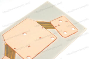
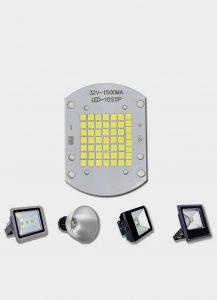
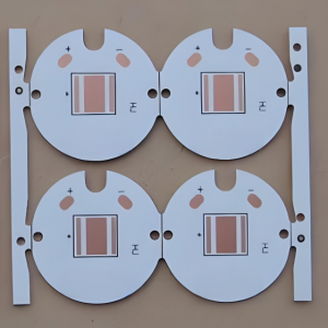
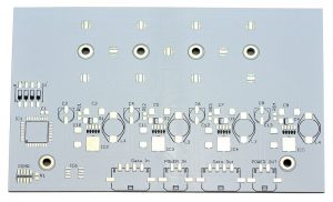
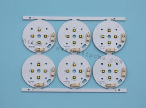
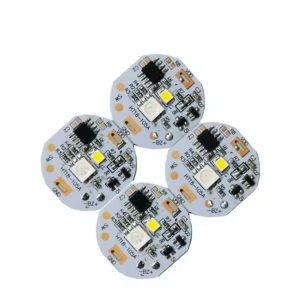
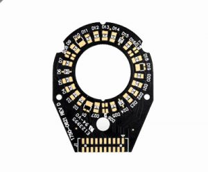
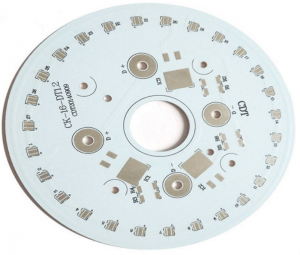
Being the market leader, we offer high quality range of LED Street Light MCPCB or Street Light PCB. These PCB are manufactured using high grade raw material under the supervision of expert and professional team with international quality standards.

Street Light

Street Light PCB

5w12V led street light mcpcb,size:14x14mm ① 10mm 5W 12V 2C2B 300mA 120- 130lm+/W
10w24V led street light mcpcb,size:18x18mm ① 13mm 10W 24V 4C2B 300mA 120-130lm+/W
15w30V led street light mcpcb,size:19x19mm ① 16mm 15W 36V 6C2B 300mA 120-130lm+/W
20w30V led street light mcpcb,size:24x24mm 019mm 20W 30V 5C4B 600mA 120-130lm+/W
20w30V led street light mcpcb,size:56x40mm 24x24mm 20W 30V 5C4B 600mA 120- 130lm+/W
30w30V led street light mcpcb,size:56x40mm 24x24mm 30W 30V 5C6B 900mA 120-130lm+/W
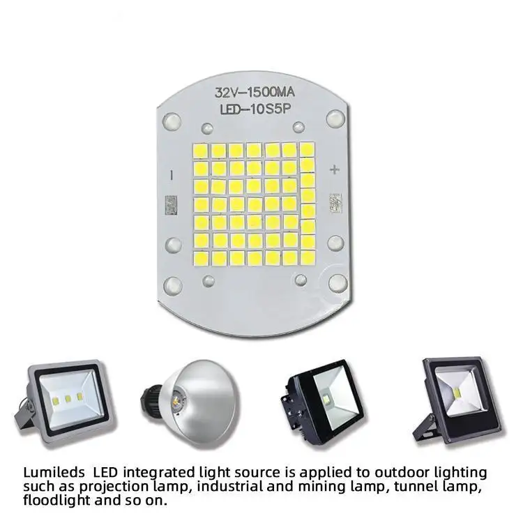
50w32V led street light mcpcb,size: 56x40mm 24x24mm 50W/4 32V 5C9B 1.5A 120-130lm+/W
50w42V led street light mcpcb,size: 56x40mm 24x24mm 50W/4 42V 7C7B 1A 120-130lm+/W
50w32V led street light mcpcb,size:56x40mm 24x24mm 50W 32V 5C10B 1.5A 120-130lm+/W
200w36V led street light mcpcb,size:194mm ① 185mm 200W 36V 10C5BM 1.5Ax4 130- 140lm+/W

These Street Light PCB are available for our valuable customers at affordable cost in market. Due to their precise design and high functionality our offered materials are ideal for making wide variety of led street light of various watt and models.

Street Light MCPCB

MCPCB production process

Substrate preparation: Select appropriate metal substrates, such as aluminum, iron, copper, indium copper, tungsten-molybdenum alloy, etc., as the base of MCPCB. These metal substrates have good thermal conductivity and are the core components of MCPCB.

Insulating dielectric layer coverage: Cover the metal substrate with an insulating dielectric layer. Common insulating dielectrics include modified epoxy resin, polyphenylene ether, polyimide, etc. This layer not only provides the insulation performance required by the circuit, but also enhances the mechanical strength and durability of the MCPCB.

Copper layer laying: Lay the copper layer on the insulating dielectric layer to form the conductive part of the circuit. The copper layer is made through the production process of printed circuit boards, and the corresponding circuits are laid according to the needs of electronic circuits.

Thermocompression bonding process: The metal substrate, insulating dielectric layer and copper layer are combined together through the thermocompression bonding process to form the basic structure of the MCPCB. This step ensures the close bonding between the layers and improves the stability and reliability of the MCPCB.

Circuit production: According to the design requirements, circuit lines are made on the copper layer. This includes drilling, dry film covering, exposure, development and other steps to ensure the accuracy and conductivity of the circuit line.

‌Inspection and testing‌: Inspect and test the completed MCPCB to ensure that its performance meets the design requirements. This includes inspection of the circuit surface and aluminum base surface, as well as testing of conductivity and insulation performance.

What are the advantages of mcpcb

Excellent heat dissipation performance: MCPCB usually adopts aluminum substrate or copper substrate, which has good thermal conductivity, can effectively dissipate the heat generated by electronic components, and improve the stability and reliability of the circuit board. This excellent heat dissipation performance makes MCPCB particularly suitable for high switching power applications, such as LED lighting, power modules, automotive electronics and power electronics, among which LED lighting is one of the most widely used fields of MCPCB.

‌High mechanical strength: The base material of metal core PCB is thicker, with high mechanical strength and bending and torsion resistance, which is conducive to the assembly and transportation of electronic products. This feature makes MCPCB perform well in environments that need to withstand greater physical pressure or frequent movement.

‌Reliable welding performance: After the surface of metal core PCB is coated with solder paste, it has good welding performance and is suitable for surface mount technology (SMT) and plug-in welding technology. This feature improves the applicability of MCPCB in PCBA processing, making it a preferred material in the manufacture of modern electronic products.

‌Corrosion and wear resistance: Metal core PCB has strong corrosion resistance and wear resistance, which is suitable for electronic products in harsh environments. This feature enables MCPCB to work stably for a long time under high temperature, humidity or other extreme conditions, improving the durability and reliability of the product.

‌Space saving‌: Compared with traditional FR-4 substrates, MCPCB has higher heat dissipation performance, which can design smaller electronic products and save space. This advantage is particularly important in devices with limited space, such as portable electronic devices such as smartphones and tablets.

‌Improve reliability‌: Good welding performance and corrosion resistance can improve the reliability and stability of the circuit board and reduce the failure rate. This is especially important in critical systems and equipment, such as medical equipment, industrial control systems, etc., where reliability and stability are crucial factors.

What accessories does a street lamp have?

  1. Lamp holder. The lamp holder of a street lamp is usually an LED lamp, which is the core part of the street lamp. It is responsible for converting electrical energy into light energy to provide lighting services for people. The quality of the lamp holder directly affects the lighting effect and life of the street lamp.
  2. Lamp pole. The lamp pole is the part that supports the lamp holder. It is usually made of metal and has various shapes such as conical poles and prismatic poles. Street lamps in different scenes may require lamp poles of different heights and shapes to meet lighting needs. In addition, safety issues should also be considered, such as anti-theft design and prevention of excessive wind force. In addition, installation accessories such as clamps are also used to fix the lamp pole.
  3. Light source. The light source is an important part of the street lamp, including LED lamp beads, bulbs, etc. The choice of light source is related to key indicators such as brightness, energy consumption and life of the street lamp. At present, LED light sources are widely used in street lamps due to their high efficiency, energy saving and long life.
  4. Electrical control device. The electrical control device includes components such as ballast, trigger, light control switch, etc., which are used to control the working state of the street lamp and protect the circuit safety. For example, light-operated switches can automatically turn streetlights on and off according to ambient light, saving energy. In addition, some advanced streetlights may also be equipped with intelligent control systems to achieve remote monitoring and management.
  5. Installation accessories. These include small parts such as clamps and screws. Although these parts are not conspicuous, they are very important for the installation and maintenance of streetlights. For example, clamps are used to fix the connection between the top of the lamp pole and the lamp head, and screws are used to fix various parts to ensure the stability and safety of the streetlight.

What are the street lights?

Ordinary street lights
Ordinary street lights are the most common lighting facilities on the streets. They usually use light bulbs or LED lamp heads and are installed on light poles to provide basic lighting for pedestrians at night.

Solar street lights
Solar street lights are an environmentally friendly street light that uses solar panels to absorb solar energy, converts energy into electrical energy, stores it in batteries, and lights up the street lights at night through control devices. Solar street lights do not need to be connected to an external power supply, have low maintenance costs, and are widely used in parks, suburban roads and other places.

LED street lights
LED street lights use light-emitting diodes as light sources, which have the advantages of high efficiency, energy saving, long life, safety and reliability. LED street lights have good lighting effects and can be intelligently adjusted according to different environments. They are the first choice for modern urban street light renovation.

Landscape street lights
In addition to the basic lighting function, landscape street lights also emphasize artistic decorative effects. It is usually integrated with the surrounding environment, with unique design and diverse shapes, and is used to increase the beauty and cultural atmosphere of street landscapes.

Multifunctional street lights
Multifunctional street lights integrate multiple functions such as lighting, monitoring, and communication. In addition to providing lighting, this type of street lamp is also equipped with cameras, display screens and other devices for urban management and security monitoring.

You may also like

Do LED lights need a circuit board?
星期四, 5 9 月, 2024

LED lights have become an integral part of modern lighting solutions, featuring energy-saving, durability, and versatility. But a common question is, do you think LED lights need a circuit board to work?

What is a LED circuit board?

An LED circuit board is a platform used to power and control light-emitting diodes (LEDs). Essentially, it is the basis for connecting all the necessary electronic components (such as resistors, capacitors, and diodes) to ensure that the LED operates safely and efficiently.

Do LED lights need a circuit board?

Circuit boards used for LEDs are usually metal core printed circuit boards (MCPCBs) because they have excellent heat dissipation properties. This is important because although LEDs are highly efficient, they still generate heat. Without proper heat management, this can lead to poor performance or shortened life of the LED.

The design and manufacture of LED circuit boards involves many aspects, including the layout of the board, the soldering of components, and the design of the driver circuit. The driver circuit is the core part of the LED circuit board, which is responsible for converting the input AC power into DC power suitable for LED use, while providing stable current and voltage to ensure the normal operation and long life of the LED.

LED circuit boards are used in a wide range of applications, from small consumer electronics to industrial lighting and automotive headlights. They provide a simplified way to control and adjust LEDs while ensuring effective heat management.

How to make a LED light circuit board?

The process of making an LED light circuit board involves multiple steps, including soldering, self-testing, cleaning, grinding, and wiring.
1. Soldering:

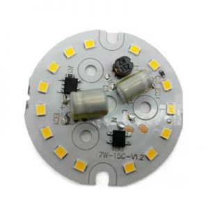
Determine the direction of the light, the side with the black rectangle is the negative end. Determine the direction of the circuit board, the end with the inner and outer wiring ports is the upper left corner. Start from the upper left light and solder in sequence to ensure that each solder joint is full and clean, without cold solder joints or leaks.

2. Self-test:

After completing the soldering, check whether the solder joints have cold solder joints, leaks, etc. Use a multimeter to touch the positive and negative terminals of the circuit board to check whether the LED lights are on at the same time.

3. Cleaning:

Use 95% alcohol to scrub the circuit board to remove residues.

4. Rubbing:

Remove the LED light circuit board from the entire board, use fine sandpaper to grind off the burrs on the edges, and make the circuit board flat.

5. Wiring:

Use blue and black thin wires to connect the circuit board. The wiring point close to the inner circle is negative and connected to the black wire; the wiring point close to the outer circle is positive and connected to the red wire. Make sure the wire is connected from the back to the front.

6. Final self-check:

Check the wiring to ensure that each wire passes through the pad and the length of the wires on both sides of the pad left on the surface is as short as possible to ensure that the circuit board can work properly.

Each step is crucial, especially the welding and wiring parts, which need to be carefully operated to ensure the performance and safety of the circuit board.

How should an LED be connected in a circuit?

LEDs should be connected to the circuit through the correct wiring method to ensure their normal operation and extend their life. ‌

Do LED lights need a circuit board?

First of all, there are three main wiring methods for LEDs: two-end wiring, single-end wiring and staggered wiring.
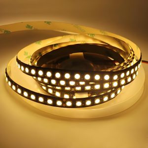
Two-end wiring is a commonly used wiring method in the early days. It is characterized by convenient wiring and simple operation. It is suitable for the replacement of fluorescent tubes.

Single-ended wiring is a safer wiring method, in which one end of the LED tube is not wired, and the two pins on the other end are respectively wired to the constant current drive power supply. This wiring method ensures that if one end of the LED tube is connected to AC power, the other end will never be charged.

Staggered wiring is an innovative wiring method that is compatible with a variety of electronic ballasts and can work normally without a starter.

When connecting LEDs, you need to pay attention to the following points:

Correctly distinguish the positive and negative poles of the LED, which can usually be judged by observing the appearance, using a multimeter or battery. Connect the anode of the LED to the positive pole of the power supply and the cathode to the negative pole of the power supply to ensure that the LED works properly.

Use appropriate resistors to limit the current to protect the LED from damage by overcurrent. The resistance value should be calculated based on the power supply voltage, the rated voltage of the LED, and the required current.

Keep the LED dry, avoid moisture or static interference, and pay attention to the temperature to avoid excessively high temperatures that affect its life and performance.

For the power connection of LED light strings, two basic forms can be used: positive connection and negative connection. The positive and negative poles of each light string correspond to the positive and negative poles of the power supply. When a large number of LED lights are connected in series, it is more practical to adopt a series-parallel combination strategy, and the number of parallel groups is determined by calculating the rated current of the power supply. ‌

Do LED lights need special wiring?

LED lights do not require special wiring, but it is necessary to determine whether a grounding wire is required based on the specific situation of the lamp. ‌

LED lights are usually designed without special wiring because they can be directly connected to AC power, thanks to the built-in rectifier of LED lights.

When installing LED lights, it is important to understand the difference between the live wire and the neutral wire, because although LED lights themselves work under DC power, they usually have built-in rectifiers and can be directly connected to household AC power.

When replacing traditional fluorescent tubes, it is necessary to remove the original ballast and starter, and directly connect the live wire and the neutral wire to both ends of the LED tube.

Regarding the issue of grounding wires, most LED lights on the market are double-insulated designs, which means that their housing and structure have met safety requirements, so no grounding wire is required. However, for lamps with metal shells, grounding is necessary to prevent people from getting electric shock when touching the bare metal.

In addition, if the bulb has a grounding wire, it is better to connect it, which can better ensure safety. It should be noted that Class III lamps are not allowed to be grounded because they use safety extra low voltage (SELV) and should be isolated from high voltage using an isolation transformer, and should not be grounded.

In summary, although LED lamps do not require special wiring, you should pay attention to safe wiring methods during installation, and judge whether a grounding wire is required according to the specific situation of the lamp to ensure safety and prevent the risk of electric shock.

Where to put resistor in LED circuit board?

In the LED circuit, the resistor should be placed between the positive pole of the LED and the first LED, that is, in front of each string of lamp beads. ‌ This placement does not depend on the specific location of the resistor, because the resistor and the LED are in series, which means that whether the resistor is placed in front of, behind, in the middle of each string of lamp beads, or anywhere randomly, the effect is the same.

Do LED lights need a circuit board?

This is because the main function of the resistor is to control the current through the LED by consuming a certain voltage and current, ensuring that the LED operates at a normal operating current and avoiding damage to the LED due to excessive current.

It is worth noting that although the position of the resistor has little effect on the LED, in actual circuit design, considering the simplicity and safety of the circuit, the resistor is usually placed close to the positive pole of the power supply. This design can avoid too many connection points in the circuit, thereby simplifying the circuit structure.

Conclusion:

LED lights usually require circuit boards for optimal performance, especially in complex or high-power applications. LED circuit boards ensure proper heat dissipation and current regulation, which are key factors in ensuring the service life and efficiency of the lighting system. BEST Technology has accumulated rich manufacturing experience in the design of LED circuit boards, and various different LED light circuits can be designed to the top level.

You may also like

What is an LED circuit board?
星期二, 3 9 月, 2024

In today’s fast-growing electronics industry, LED (light-emitting diode) technology has become a game-changer in lighting and display applications. LED PCB (printed circuit board) is essential for effectively powering and controlling LEDs. It plays a key role in ensuring the efficiency, lifespan and performance of LED lighting systems.

As the demand for energy-efficient lighting solutions continues to increase, understanding the complexity of LED light PCB design has become critical for engineers, designers and manufacturers. These circuit boards require special manufacturing steps in addition to design guidelines.

What is led light circuit board?

LED light circuit board is the abbreviation of printed circuit board, which is mainly used to carry and connect electronic components of LED lamps. ‌LED light circuit board is usually made of aluminum substrate and FR-4 fiberglass circuit board, where the LED aluminum substrate is printed on the aluminum plane with good thermal conductivity, and then the electronic components are soldered on it. ‌This design helps to improve the heat dissipation performance and stability of LED lamps, and ensure that the LED lamps can work stably for a long time.

What is an LED circuit board? How to make it?

The main function of LED light circuit board is to provide power to LED lamp beads and control the brightness and color of its LED lamp beads. In order to light up the LED lamp beads, an LED driving circuit is required, which includes constant voltage driving, constant current driving, PWM driving and other methods, which are usually integrated on the small circuit board of the LED lamp.

In addition, the design and manufacture of the LED lamp circuit board take into account the characteristics of LED, such as long life, high light efficiency, no radiation and low power consumption. Compared with traditional light sources, such as incandescent lamps and fluorescent lamps, LED lamps have significant advantages in efficiency, life and environmental protection.

How to make led light circuit board?

The process of making LED lamp circuit boards involves multiple steps, including welding, self-inspection, mutual inspection, cleaning, friction, wiring, etc.

Determine the direction of the lamp: the front side is facing up, and the side with the black rectangle is the negative end.

Determine the direction of the circuit board: the front side is facing up, and the end with two internal and external wiring ports is the upper left corner.

Welding: Carefully weld each solder joint to ensure fullness, cleanness, and no false soldering or leaking. ‌

What is an LED circuit board? How to make it?

Self-inspection: After completing the welding, first check whether there is a cold solder joint, leaking solder joint, etc. Use a multimeter to touch the positive and negative terminals of the circuit board to check whether the LED lights are on at the same time. ‌

Mutual inspection: After the self-inspection, it will be handed over to the person in charge for inspection. Only with the consent of the person in charge can it flow into the next process. ‌

Cleaning: Use 95% alcohol to scrub the circuit board to remove residues and keep the circuit board clean.

Friction: Use fine sandpaper (coarse sandpaper if necessary) to grind off the burrs on the edge of the circuit board so that the circuit board can be placed flatly in the fixing seat. ‌

Wiring: Use blue and black thin wires to connect the circuit board. The wiring point close to the inner circle is negative and connected to the black wire; the wiring point close to the outer circle is positive and connected to the red wire. ‌ Make sure the wires are connected from the back to the front. ‌

Self-check and mutual check: Check the wiring to ensure that each wire passes through the pad, the length of the wires on both sides of the pad that remain on the surface should be as short as possible, and the thin wires will not break or loosen when gently pulled. ‌‌

Through the above operations, the production of the LED lamp circuit board can be completed. ‌Each step is crucial, especially the welding and wiring parts. It is necessary to ensure the quality of the welding points and the correct connection of the wires to ensure the normal operation of the circuit board and the normal lighting of the LED lamp.

Why do you need a resistor with an LED?

When using LED, a resistor needs to be connected in series to control the current, prevent excessive current from damaging the LED, and ensure that the LED can emit light normally. ‌

LED is a semiconductor device that can directly convert electrical energy into light energy. Due to its special material properties, LED is very sensitive to current, and excessive or insufficient current may cause the LED to malfunction or be damaged.

Therefore, when the LED is connected to the power supply, a resistor is needed to limit the current to ensure that the LED can work stably and safely.

The main function of this resistor is voltage division and current limiting. It is used to adjust the current passing through the LED to prevent the LED from burning out due to excessive current, while also ensuring that the LED can emit light of appropriate brightness.

Specifically, when current passes through the LED, the resistor will produce a certain voltage drop, thereby reducing the voltage applied to both ends of the LED, thereby controlling the current passing through the LED.

What resistor to use with LED?

Use an LED resistor calculator to help determine the required resistor value. ‌

When using LEDs, in order to protect the LED and ensure its normal operation, it is usually necessary to limit the current by connecting an appropriate resistor in series. This is because each LED has a maximum current value, exceeding which may cause the LED to be damaged.

Using an LED resistor calculator can help you determine the required resistor value to ensure that the current does not exceed the maximum tolerance of the LED.

By entering the relevant parameters of the LED (such as the rated current and voltage), the calculator will automatically calculate the required resistor value to protect the LED from overcurrent damage.

This method is a common practice and is applicable to any situation where a number of LEDs are used in series. In this way, the safe operation of the LED can be ensured while avoiding damage caused by excessive current.‌

How to improve the heat dissipation performance of LED light circuit boards?

The key to improving the heat dissipation performance of LED light circuit boards is to optimize the heat dissipation path, use efficient heat dissipation materials, and adopt advanced heat dissipation technology.

Optimize the heat dissipation path:

Understanding the heat transfer path of the heat generated by LED components is the first step to improve heat dissipation performance. Heat moves from the LED components through the package wires to the circuit board, and then dissipates through the heat sink.

The heat dissipation efficiency can be effectively improved by using materials with good thermal conductivity, expanding the cross-sectional area of the path (such as using thick copper wire), and applying thermal lubricants to reduce the gaps in the connection parts.

Use efficient heat dissipation materials:

Metals such as copper and aluminum are often used to make heat sinks because of their good thermal conductivity. In addition, new materials such as graphene are also used to make heat sinks because of their excellent thermal conductivity. These materials can significantly improve heat dissipation efficiency. ‌

Adopting advanced heat dissipation technology:

Micro-groove group composite phase change integrated cooling technology is an advanced heat dissipation technology. It effectively removes the heat of high-power electronic devices by changing the closed-circulation cooling medium into a nano-scale water film and utilizing its strong evaporation ability and latent heat exchange ability.

As an excellent thermal conductive medium, thermal conductive silicone grease has excellent electrical insulation and thermal conductivity. It can penetrate into the tiny depressions on the metal surface, increase the contact area, and improve the efficiency of heat conduction from the LED chip to the aluminum substrate.

Are LED PCBs only used in lighting systems?

The application range of LED PCB (printed circuit board) is far more than lighting systems. In addition to lighting systems, LED PCB is also widely used in other fields. For example, LED lamps are one of the most common products using LED PCBs. Whether it is home lighting, commercial lighting or outdoor lighting, LED lamps occupy a large market share.

Compared with traditional incandescent lamps and energy-saving lamps, LED lamps have higher luminous efficiency, longer service life and lower energy consumption. They also have features such as dimming and color change, which can meet the needs of different scenarios. ‌

In addition, LED PCB is also used in LED display screens, LED backlight sources and automotive lighting. LED display screens provide high-definition and high-brightness display effects in large-scale events such as sports events, concerts, and exhibitions, bringing a shocking visual experience to the audience.

LED backlight sources have become the mainstream choice in electronic products such as LCD monitors, mobile phones, and tablet computers. Compared with traditional cold cathode fluorescent lamps, LED backlight sources have higher brightness, longer service life and lower energy consumption. At the same time, they can achieve local dimming, improve display effects and reduce energy consumption.‌

What is an LED circuit board? How to make it?

In the field of automotive lighting, with the advancement of automotive lighting technology, more and more cars are beginning to use LED lamps. Compared with traditional halogen and xenon lamps, LED car lights have higher brightness, longer service life, lower energy consumption, faster response speed and better heat dissipation performance, which improves driving safety. ‌

From this we can know that the application of LED PCB is not limited to lighting systems, but is widely used in many fields, including but not limited to lighting, display technology, backlight sources of electronic products, and automotive lighting. ‌

Conclusion:

Designing PCB for LED lights is a complex but critical task that requires careful consideration of various influencing factors, from the selection of manufacturing materials to the testing of thermal conductivity and the quality testing of finished products. Choosing Best Technology has expert design assistance and reliable manufacturing processes, which will allow you to obtain the best results for LED light PCB design. ‌

You may also like

How do you identify a diode symbol?
星期三, 21 8 月, 2024

‌A diode is an electronic component with unidirectional conductivity. Its circuit symbol usually includes an arrow pointing to a vertical line, which represents the positive pole, while the vertical line represents the negative pole. This representation method is suitable for most types of diodes. If the diode symbol is bidirectional, it means that it has no polarity.

What is the symbol of diode LED?

The symbol of a diode in a circuit diagram usually consists of an arrow pointing to a vertical line, with a line extending from the arrow, where the arrow represents the positive pole of the diode and the vertical line represents the negative pole. If it is bidirectional, there is no polarity. In addition, there will be obvious markings on the appearance of the diode to distinguish its polarity.

How do you identify a diode symbol?

Do LED diodes have a positive and negative?

LED diodes have a positive and negative pole. ‌

How do you identify a diode symbol?

LED diodes are electronic devices with two electrodes: positive (anode) and negative (cathode). These two electrodes play different roles in the circuit. The positive pole is the end point where the current enters, and the negative pole is the end point where the current flows out. The unidirectional conductivity of the LED diode means that it will only conduct when a forward voltage is applied to its two ends, that is, it allows current to pass; when a reverse voltage is applied, it is cut off, preventing current from passing. This characteristic allows the LED diode to be used as a switch in the circuit to control the direction of current flow.

In practical applications, it is very important to determine the positive and negative poles of the LED diode, because incorrect connection may cause damage to the device or malfunction.

How to identify LED positive and negative?

There are many ways to determine the positive and negative poles of the LED diode, including observing the pin length, the position of the missing corner, the shape and size of the pin, the direction of the surface marking, etc. Some LEDs will have a “T” or inverted triangle symbol at the bottom, where the horizontal side of the “T” is the positive pole and the other side is the negative pole.

How do you identify a diode symbol?

1. Observe the pin length: For direct-plug LED lamp beads, the longer end of the pin is usually the positive pole, and the shorter end is the negative pole. This is because the positive electrode is usually designed to be longer than the negative electrode during the manufacturing process.

2. Observe the size of the internal electrode: Inside the LED lamp bead, the smaller end is usually the positive pole, and the larger end is the negative pole.

3. Check the printed mark on the back of the board: On the back of the board of the SMD LED lamp bead, there is usually a “T”-shaped or inverted triangle symbol, where one end close to the horizontal side or the triangle side is the positive pole, and the other end is the negative pole.

4. Observe the printed lines on the board: One side of the colored line is usually the negative pole, and the other side is the positive pole.

5. Determine the size of the pad: The larger pad is the negative pole, and the smaller pad is the positive pole.

6. Check the missing corner of the front panel: One end of the missing corner is often the positive pole, and the other end is the negative pole.

7. Use a multimeter to test: Set the multimeter to the resistance or diode range. If the lamp bead lights up, the red test pen is in contact with the positive pole. When the light is on, the red test lead is connected to the positive pole and the black test lead is connected to the negative pole.

8. Use battery test: Use a 1.5V battery to connect the LED lamp bead. If the lamp bead lights up, the positive pole of the battery is connected to the positive pole of the LED lamp bead.

Through the above method, the positive and negative poles of the LED lamp bead can be effectively determined to ensure the correct connection of the circuit and avoid damage to the LED lamp bead.

What color is LED diode?

The color of the LED diode can be red, green, blue, yellow, white, etc. ‌

How do you identify a diode symbol?

The color of the LED diode mainly depends on the semiconductor material used. According to different application requirements, LED diodes can emit different colors of light, including but not limited to red, green, blue, yellow and white. In addition, white LEDs can be further subdivided into warm white, neutral white, pure white and cold white. The differences in these colors are mainly reflected in color temperature and hue, so as to meet different lighting and display needs.

1. Red LED: Mainly used in occasions such as indicator lights to provide eye-catching visual signals.

2. Green LED: Commonly used for digital display in display devices, such as calculators and electronic displays.

3. Blue LED: Combined with red and green LEDs, it can produce white light and is an important component in modern lighting technology.

4. Yellow LED: Used in various indicator lights and display devices to provide eye-catching visual prompts.

5. White LED: By combining red, green and blue primary color LEDs, it can produce rich colors and high-quality white light, which is widely used in lighting and display technology.

The packaging method of LED diodes also affects their appearance and application areas. For example, surface mount LEDs (SMD) are widely used in various electronic products due to their small and light characteristics. In addition, LED diodes can also be classified according to current levels to meet the needs of different circuits. These characteristics make LED diodes an indispensable component in modern electronic technology and lighting.

What happens if LED polarity is reversed?

LED polarity reversal may cause the LED light to not light up or be damaged. ‌

When the positive and negative poles of an LED lamp are connected in reverse, the following situations may occur:

1. No light: This is the most common situation because the current flows through the LED in the opposite direction to the normal situation, causing the LED to not light up normally.

2. Unstable light: In some cases, certain types of LEDs may cause unstable light, such as flickering or frequent dimming, due to reverse polarity connection.

3. Damaged LED: Although some new LEDs may be able to withstand incorrect connections with reverse polarity, most common LEDs may burn out when the polarity is reversed, causing them to not work properly.

4. Lamp does not light up: If the positive and negative poles of an LED lamp are connected in reverse, it will generally not burn out, but it may cause the lamp to not light up. This may be because the current cannot pass through the LED normally, or because the circuit protection mechanism is activated due to reverse polarity, thereby preventing the current from passing.

Why do LED diodes fail?

The main reasons for the failure of LED diodes include overheating, overvoltage breakdown, current overload, and aging effects. ‌

‌Overheating‌: When the heat generated by the LED during operation cannot be effectively dissipated, the temperature is too high, which may damage the internal structure of the LED and affect its performance.

‌Overvoltage breakdown‌: When the voltage across the LED exceeds its rated value, it may cause damage to its internal structure and fail.

‌Current overload‌: If the current flowing through the LED exceeds its rated value, it may cause the LED to burn out. Current overload is usually caused by improper circuit design or external factors.

‌Aging effect‌: Over time, LEDs may fail due to material aging. Aging effects are usually manifested as performance degradation, increased leakage current, etc.

‌Electrostatic discharge (ESD) damage‌: When the LED is subjected to electrostatic discharge shock, its internal structure may be damaged. To prevent electrostatic discharge damage, appropriate anti-static measures should be taken‌.

How do I know if my LED diode is bad?

If the LED diode can emit light normally under the appropriate operating voltage, it means that it is fine‌.

Make sure that the positive and negative poles of the LED diode are correctly connected to the circuit. Use the voltage measurement function of the multimeter to test the open circuit voltage of the circuit. If the test voltage is different from the expected value, there may be a problem with the circuit connection or the LED light-emitting diode.

Use the “diode test” position of the multimeter to test the diode. Insert the diode into the test hatch, connect the anode and cathode of the diode with the clamp, and connect the cathode to the test port. Observe the reading of the multimeter. If the reading is positive, it means that the diode is normal and can be turned on; if the reading is negative, it means that the diode is not good and cannot be turned on or reverse conduction.

Conclusion:

The application of diodes in daily electronics is very extensive. It can be used in almost all electronic circuits. The key to identifying diode symbols is to understand their basic shape and signs. It is necessary to correctly understand the symbol of the diode so that it can be safer and more efficient during use. ‌

You may also like

led light circuit board
星期五, 26 7 月, 2024

The led light circuit board, also called the LED circuit board, is actually the abbreviation of the printed circuit board (PCB). PCB is a stable carrier of electronic components, which not only realizes electrical connection, but also plays a supporting role. In LED lamps, the PCB board integrates LED components, and through this integrated PCB board, the LED lamp can realize its function. The driving circuit of the LED lamp, such as constant voltage drive, constant current drive, PWM drive, etc., are all integrated on this small circuit board, which is necessary to light up the LED lamp beads. Therefore, it can be said that the circuit board of the LED lamp is the printed circuit board inside it, which is responsible for converting electrical energy into visible light, and controlling the brightness and performance of the LED through different driving methods.

Customized process of led light circuit board

  1. Support small and medium batch orders of 1-14 layers, consult customer service for more layers;
  2. Can do HDI blind buried hole process;
  3. The board uses Jiantao A-grade board (KB-6164), which can be made into halogen-free board;
  4. The maximum size can be one meter;
  5. Various ink colors such as pink, transparent, purple, etc.;
  6. Support copper thickness of 10oz, hole copper 35μm;
  7. Multi-layer board can be customized with pressing structure;
  8. Support multi-level impedance matching;
  9. Board edge copper package, two-color ink, plug hole, countersunk hole, square groove, stepped hole, stepped groove, nickel palladium gold and other special processes;
  10. PCBA can be pasted in one set, single and double sides can be pasted;
led light circuit board

led light circuit board

What fields can led light circuit board be applied in?

PCB LED lamp has excellent energy efficiency, low cost and maximum design flexibility, so it can be incorporated into many lighting applications.

Telecommunications: LED indicators and displays are always used in telecommunications equipment due to the surrounding machinery, and they have great heat transfer capabilities. Therefore, aluminum-based LED PCBs play an important role in their applications.
Automotive: Aluminum PCB LEDs are also used in the indicator lights, brake lights, and headlights of automobiles, among other applications. There are factors that make aluminum PCBs ideal in the automotive industry, such as durability and competitive pricing.
Computers: LED displays and indicator lights are becoming increasingly popular in computer applications. Aluminum PCB LEDs are an ideal solution due to the heat sensitivity of computer machinery. In addition to LED applications, aluminum PCBs are also used in computer components such as power supply units and CPU boards due to their ability to dissipate and transfer heat.
Medical: Lighting tools used in surgical procedures and medical examinations often use high-power LED lights, which often use aluminum PCBs, mainly because of the durability and heat transfer capabilities of aluminum PCB LEDs – this ensures that medical equipment operates properly, regardless of the number of patients that are cycled through the medical office. In addition to lighting tools, medical scanning technology also often uses aluminum PCBs.

led light circuit board

What fields can LED PCB be applied in?

Advantages of led light circuit board

Lower power consumption: Replacing incandescent lamps with LED lamps can reduce power consumption by more than 80%.

Longer life: The service life of LEDs can generally exceed 20,000 hours, and they can be used around the clock for 3 years, which is 25 times longer than incandescent lamps. Not only can it save costs, but it also reduces the frequency of replacement.

Higher efficiency: Incandescent lamps release more heat. LED lamps can reduce it by up to 20%. This means that while using more powerful LED lamps, unnecessary heating can be reduced.

Smaller size: Due to their small size, LED lamps can have various sizes and can be used in different places. Manufacturers can add LEDs to anything, whether it is electronic equipment or cars, and even traffic lights and signs on the road.

Environmental protection: Compared with other bulbs, LED lamps do not contain mercury. Therefore, LEDs have less impact on the environment and are easier to handle.

LED is the abbreviation of light-emitting diode, which is a semiconductor diode. LEDs are soldered to a printed circuit board and equipped with a chip that generates light through electrical connections. A heat sink and a ceramic base are used to connect the chip. Undoubtedly, LED PCB is the core of LED lighting. An LED PCB tends to generate a lot of heat, but it is difficult to cool it by traditional methods. Metal core PCB is widely used in LED applications due to its strong heat dissipation ability, especially aluminum is often used in the production of PCB for LED lamps. Usually, aluminum PCB contains a thin layer of thermal conductive medium material, which can transfer and dissipate heat much more efficiently than traditional rigid PCB.

Why led light circuit board use mcpcb

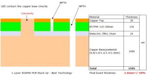
Aluminum substrate is a metal-based copper-clad board with good heat dissipation function. Generally, a single-sided board consists of three layers, namely circuit layer (copper foil), insulation layer and metal base layer. There are also designs for high-end use as double-sided boards, with the structure of circuit layer, insulation layer, aluminum base, insulation layer and circuit layer. Very few applications are multi-layer boards, which can be made of ordinary multi-layer boards with insulation layer and aluminum base.
LED aluminum substrate is PCB, which also means printed circuit board, but the material of the circuit board is aluminum alloy. In the past, our general circuit board material was glass fiber, but because LED generates more heat, the circuit board used for LED lamps is generally aluminum substrate, which can conduct heat quickly. The circuit boards used for other equipment or electrical appliances are still glass fiber boards!

How are LED patches installed on PCB boards?

Use double-sided PCB board, patch LED on the front, and drive power circuit on the back. LED can be designed into a circle shape, through metallized holes to the back, there are plenty of places to handle these leads
On the corresponding pads of PCB board, brush tin, use patch machine to apply it, and then reflow soldering, it is on, but in actual operation, you need to pay attention to many problems, anti-static, equipment quality, etc.

You may also like

Why is the MCPCB Widely Used in the LED Products?
星期六, 30 4 月, 2022

MCPCB refers to metal core printed circuit board. It has a good performance in heat dissipation, so it is often used in LED products.

The advantages of MCPCB

Prevent overheating: 

LEDs tend to get overheated very quickly. If a metal core printed circuit board is used, it solves overheating by transferring the energy from one side to another.

Improve the material’s reliability: 

The MCPCB plays a key role in the elements that heats up overly at times. It helps to divert the heat from one side to another where the heat has vanished, which improves the product’s life, making it much more durable.

Adapt to a high temperature: 

Unlike the FR4 technology, the metal core printed circuit board can adapt to products with a high temperature, hence it proves to be very useful for LED products.

LED PCB

Why is the MCPCB widely used in the LED products?

Since it is well-known that the LED products will emit a lot of heat. Based on the advantages, the metal core PCB can transfer heat quickly and prevent overheating. And Aluminum PCB is mostly used in metal core PCBs, for they can operate longer than other metals and longer shelf life.

Moreover, metal core PCB has a high conductive ability, hence there remains ample space for maximum LEDs, which allows producing sufficient light and achieving high performance.

Therefore, based on the advantages of the MCPCB, it is the prior option of the material for the LED products.

So, this is the end of the article. In case if you have any questions, you are welcome to contact us via email at  sales@bestpcbs.com. We are fully equipped to handle your PCB or MCPCB manufacturing requirements.

You may also like

LED Lighting: MC-PCBs
星期三, 13 11 月, 2019

LEDs are pretty hot nowadays! Not just the biggest tendency in lighting, but also require a lot of heat dissipation that standard PCB material just can’t handle. So what’s the solution? Metal PCBs. Standard PCB material typically has a thermal conductivity of 0.5 W/m K; which is not adequate for the current high intensity LEDs. With MCPCB materials you can increase the life of your LEDs with better heat dissipation.

What’s the thermal conductivity of MCPCB material?

Up to now, Best Technology has helped many customers with their MCPCB needs and have found the most common questions as shown below:

What is the most cost effective MCPCB?

How do you layout an MCPCB?

Can I get a different dielectric thickness between the metal and circuit layer?

Can I put plated through holes on an MCPCB?

Can I do more than one layer with an MCPCB?

How quick can a MCPCB be manufactured?

What Metals can be used?

The professional staff at Best Technology can help you resolve these questions and even more. Need help getting started? Contact us today.

You may also like