What is underfill dispensing, and why is it vital for electronic component reliability, especially in consumer, automotive, and aerospace industries? Many manufacturers struggle with costly defects, inconsistent results, and wasted resources when implementing this process. The good news? This blog reveals the secrets to mastering underfill dispensing from core basics to pro-level optimization to eliminate pain points and boost quality. Read on to unlock the key to reliable, efficient underfill application.
What is Underfill Dispensing and Why Is It Critical for Electronic Components?
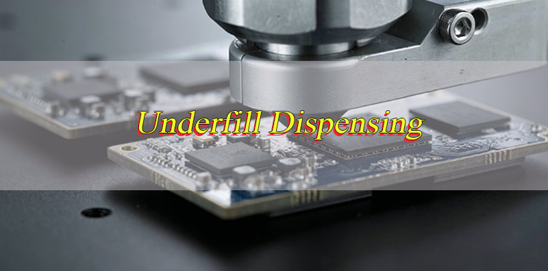
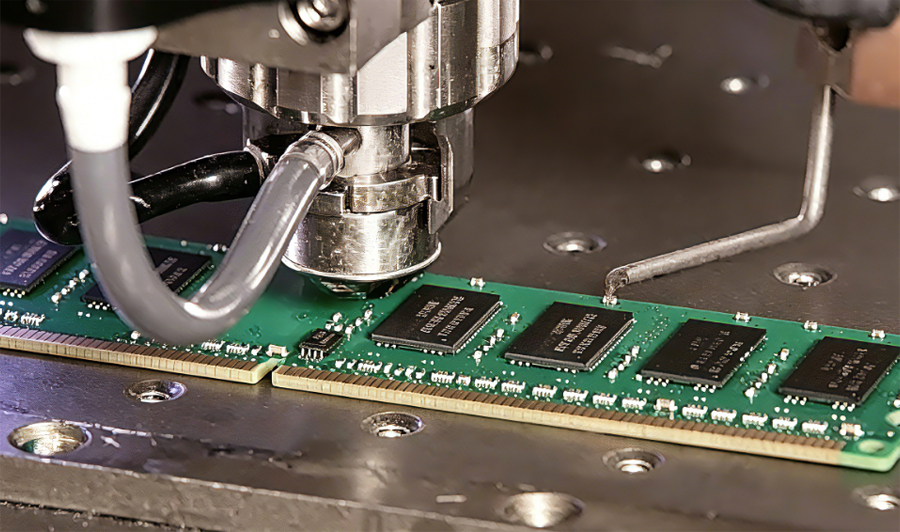
Underfill dispensing is a specialized application process that deposits a protective adhesive material beneath electronic components such as BGA, CSP, and flip chip packages. This material flows into the gaps between the component and the printed circuit board, forming a strong bond that reinforces the connection between the component and the board.
The primary purpose of underfill dispensing is to protect solder joints from external stressors that can cause failure over time. Electronic components are often exposed to thermal cycling, mechanical vibration, and environmental factors like humidity, which can lead to solder joint fatigue, cracking, or separation. Underfill material acts as a buffer, absorbing thermal expansion differences between the component and the board, reducing stress on solder joints and extending the overall lifespan of the electronic device.
Without proper underfill application, electronic components are at high risk of premature failure. This is especially critical in high-reliability industries such as automotive, aerospace, and medical devices, where component failure can lead to safety hazards, costly recalls, or operational downtime. Even in consumer electronics, underfill dispensing ensures devices remain durable through daily use, reducing warranty claims and improving customer satisfaction.
What Types of Underfill Dispensing Equipment Are Used in Different Production Scenarios?
The right underfill dispensing equipment depends on production volume, component size, precision requirements, and budget constraints. Below are the most common types used in various manufacturing scenarios:
- Manual Dispensing Syringes: Ideal for low-volume production, prototyping, or small-batch runs. These are simple, cost-effective tools that require manual operation to control the flow of underfill material. They work best for large components with relaxed precision requirements, as they rely on operator consistency.
- Semi-Automatic Dispensing Systems: Combine manual component loading with automated dispensing. These systems feature a programmable dispenser that controls flow rate, dispense time, and path, reducing operator error. They are suitable for medium-volume production where precision is important but full automation is not yet feasible.
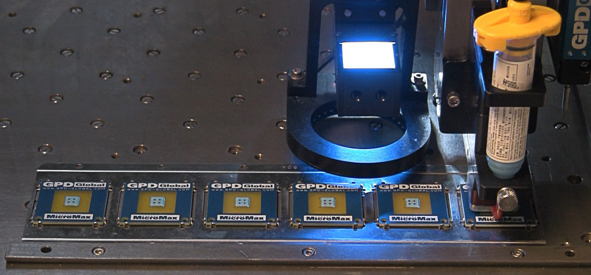
- Automatic Vision-Controlled Dispensing Machines: Equipped with cameras and advanced software to align components and dispense underfill with high precision. These machines integrate with production lines, enabling high-volume, high-accuracy dispensing for small components like micro BGAs and flip chips. They are widely used in consumer electronics manufacturing.
- Jet Dispensing Systems: Use a non-contact method to deposit underfill material, eliminating the risk of component damage from needle contact. They offer fast dispensing speeds and high precision, making them ideal for high-volume production of miniaturized components, such as those used in smartphones and wearables.
- Vacuum-Assisted Dispensing Equipment: Designed for components with tight gaps or complex geometries where air entrapment is a concern. These systems use vacuum pressure to draw underfill material into hard-to-reach areas, ensuring complete coverage and reducing defects like voids.
How to Choose the Right Underfill Dispensing Pattern for BGA and Flip Chip Applications?
Selecting the correct underfill dispensing pattern is critical to ensuring complete coverage, minimizing defects, and optimizing production efficiency. The choice depends on component type, size, gap height, and underfill material properties. Below are guidelines for BGA and flip chip applications:
- Single-Side Line Dispensing: Apply a continuous line of underfill along one edge of the BGA or flip chip. This pattern works best for components with large gap heights (greater than 50μm) and high-flow underfill materials. It is simple to program and ideal for medium-sized BGAs.
- Two-Side Line Dispensing: Dispense underfill along two opposite edges of the component. This pattern reduces filling time by allowing underfill to flow from two directions, ensuring faster coverage. It is recommended for larger BGAs (greater than 15mm) or components with moderate gap heights.
- Corner Dot Dispensing: Deposit small dots of underfill at each corner of the component. This pattern is suitable for small BGAs and flip chips with tight gap heights (less than 30μm). The dots flow inward to cover the entire component bottom, reducing the risk of overflow.
- Perimeter Dispensing: Apply a continuous line of underfill around the entire perimeter of the component. This pattern ensures uniform coverage and is ideal for components with irregular shapes or those requiring maximum protection against environmental factors. It works well with low-flow underfill materials.
- Spiral Dispensing: Create a spiral pattern of underfill on the component surface, which spreads evenly as it flows into the gaps. This pattern is effective for components with high-density solder joints, as it ensures no areas are missed and reduces the risk of voids.
- Center Dispensing: Deposit underfill at the center of the component, allowing it to flow outward to the edges. This pattern is suitable for flip chips with small footprints and uniform gap heights. It minimizes underfill waste and ensures consistent coverage.
- Staggered Line Dispensing: Apply alternating lines of underfill along the component edges, which helps distribute the material more evenly and reduces filling time. This pattern is recommended for large BGAs with varying gap heights or uneven solder joint distributions.
- Custom Pattern Dispensing: Program a unique pattern tailored to the specific component geometry. This is necessary for complex components with asymmetrical designs, cutouts, or non-standard shapes, ensuring complete coverage in all critical areas.
What Preparations Are Needed Before Starting the Underfill Dispensing Process?
Proper preparation is essential to avoid defects and ensure consistent underfill dispensing results. The following steps must be completed before starting the process:
- Inspect Components and PCBs: Check for any damage, contamination, or misalignment. Components with bent pins, cracked solder joints, or debris on the bottom will cause underfill defects. PCBs should be free of dust, flux residues, and moisture.
- Store Underfill Material Correctly: Underfill adhesives are often temperature-sensitive and require refrigerated storage (2–8℃) to maintain their properties. Allow the material to reach room temperature (25±2℃) before use to prevent moisture condensation and ensure proper flow.
- Calibrate Dispensing Equipment: Verify that the dispenser’s flow rate, dispense time, and needle position are calibrated to the required specifications. Use a scale to measure dispensed material volume and adjust settings as needed to ensure accuracy.
- Prepare the Work Environment: Maintain a clean, temperature-controlled workspace (25±2℃, 40–60% RH) to prevent moisture absorption and ensure consistent underfill flow. Use HEPA filters to reduce dust and contaminants.
- Test Underfill Material Compatibility: Ensure the underfill material is compatible with the component and PCB materials. Conduct a small test run to check for adhesion issues, flow rate, and curing time.
- Set Up Fixtures and Alignment Tools: Use fixtures to secure PCBs and components in place, ensuring proper alignment during dispensing. Misalignment can lead to uneven underfill coverage and solder joint stress.
- Check Curing Equipment: Verify that ovens or curing stations are set to the correct temperature and time settings, as specified by the underfill material manufacturer. Improper curing will compromise the adhesive’s strength and protective properties.
How Does Pre-Heating Affect the Underfill Dispensing Process and Final Results?
Pre-heating is a critical step in underfill dispensing, as it directly impacts material flow, void formation, and curing quality. The following points outline its key effects:
- Reduces Underfill Viscosity: Pre-heating the PCB and component lowers the viscosity of the underfill material, allowing it to flow more easily into the gaps between the component and the board. This ensures complete coverage, especially for components with tight gap heights (less than 50μm).
- Minimizes Void Formation: Moisture trapped in the PCB or component can evaporate during pre-heating, reducing the risk of voids in the underfill layer. Voids weaken the bond between the component and the board, increasing the chance of solder joint failure.
- Improves Adhesion: Pre-heating cleans the surface of the PCB and component by removing flux residues and contaminants, enhancing the adhesion of the underfill material. This results in a stronger bond and better long-term reliability.
- Controls Curing Time: Consistent pre-heating ensures the underfill material cures uniformly, preventing uneven curing that can lead to stress cracks. It also shortens the overall curing time, improving production efficiency.
- Prevents Thermal Shock: Gradual pre-heating reduces thermal shock to the component and PCB, which can cause damage to solder joints or the component itself. This is especially important for delicate components like flip chips.
- Optimizes Flow Rate: Pre-heating at the correct temperature (typically 80–120℃, depending on the underfill material) ensures a consistent flow rate, reducing the risk of overflow or incomplete filling. Incorrect pre-heating temperatures can either slow flow (too low) or cause premature curing (too high).
What is the Process of Underfill Dispensing?
Underfill dispensing follows a structured, step-by-step process to ensure consistency and quality. Each step must be executed precisely to avoid defects and ensure optimal performance:
Step 1: Component and PCB Preparation. Clean and inspect the PCB and component to remove any contaminants, dust, or flux residues. Secure the PCB in a fixture to ensure stability during dispensing.
Step 2: Pre-Heating. Place the PCB and component in a pre-heating station set to the manufacturer’s recommended temperature (80–120℃). Hold the temperature for 5–10 minutes to remove moisture and reduce underfill viscosity.
Step 3: Equipment Setup. Load the underfill material into the dispensing equipment and calibrate the flow rate, dispense time, and needle position. Ensure the needle is aligned with the component edge to prevent damage.
Step 4: Dispensing. Execute the selected dispensing pattern (e.g., line, dot, perimeter) to deposit the underfill material. Monitor the flow to ensure uniform coverage and avoid overflow or underfilling.
Step 5: Flow and Wetting. Allow the underfill material to flow into the gaps between the component and the PCB. This process, known as capillary flow, typically takes 1–5 minutes depending on the material and gap height.
Step 6: Inspection. Use visual inspection or X-ray imaging to check for voids, incomplete coverage, or overflow. Reject or rework any components that do not meet quality standards.
Step 7: Curing. Place the PCB and component in a curing oven set to the recommended temperature (120–150℃) for the specified time (30–60 minutes). This hardens the underfill material, forming a strong bond.
Step 8: Post-Curing Inspection. Conduct a final inspection to verify the underfill layer’s integrity, adhesion, and absence of defects. Ensure the component is securely bonded to the PCB and meets all performance requirements.
What are the Parameters to Control During Underfill Dispensing?
Controlling parameters during underfill dispensing is critical to achieving consistent results and minimizing defects. The following table outlines the essential parameters, their recommended ranges, and their impact:
| Parameter | Recommended Range | Impact |
|---|---|---|
| Flow Rate | 0.1–1.0 mL/min | Controls the amount of underfill dispensed per minute. Too high causes overflow; too low leads to incomplete coverage. |
| Dispense Time | 0.5–5.0 seconds | Determines the volume of underfill deposited. Incorrect times result in underfilling or overflow. |
| Needle Height | 0.5–2.0 mm above component | Affects material placement. Too low damages components; too high causes uneven dispensing. |
| Pre-Heating Temperature | 80–120℃ | Reduces viscosity and moisture. Too low slows flow; too high causes premature curing. |
| Curing Temperature | 120–150℃ | Ensures proper hardening. Too low results in weak adhesion; too high damages components. |
| Curing Time | 30–60 minutes | Determines underfill strength. Insufficient time leads to incomplete curing; excess time wastes production resources. |
| Underfill Viscosity | 500–2000 cP at 25℃ | Affects flowability. Too high prevents gap filling; too low causes overflow. |
| Ambient Temperature | 23–27℃ | Maintains consistent material properties. Fluctuations cause viscosity changes and inconsistent dispensing. |
What Industry Standards Should Be Followed in the Underfill Dispensing Process?
Adhering to industry standards ensures underfill dispensing meets quality, reliability, and safety requirements. The following standards are widely recognized and followed in manufacturing:
- IPC-7095: Provides guidelines for the design and implementation of underfill processes for flip chip and BGA components. It covers material selection, process parameters, and quality requirements.
- IPC-A-610: Outlines acceptability criteria for electronic assemblies, including underfill application. It specifies allowable defects, such as voids, overflow, and incomplete coverage.
- ISO 9001: Ensures a quality management system is in place for underfill dispensing, covering process control, documentation, and continuous improvement.
- JEDEC J-STD-020: Details requirements for the handling and processing of moisture-sensitive components, including pre-heating and storage guidelines for underfill materials.
- IPC-6012: Specifies performance requirements for rigid printed circuit boards, including surface cleanliness standards that impact underfill adhesion.
- Automotive Electronics Council (AEC-Q100): Applies to automotive electronic components, requiring underfill dispensing to meet strict reliability standards for thermal cycling and mechanical stress.
How to Avoid Common Defects in the Underfill Dispensing Process?
Common defects in underfill dispensing can be avoided through proper process control, equipment maintenance, and material management. The following steps address the most frequent issues:
- Voids: Ensure proper pre-heating to remove moisture, use vacuum-assisted dispensing for tight gaps, and select underfill materials with low volatility. Avoid excessive dispense speed, which can trap air.
- Incomplete Coverage: Calibrate flow rate and dispense time to ensure sufficient material volume, select the correct dispensing pattern for the component, and verify underfill viscosity is within the recommended range.
- Overflow: Adjust needle height and dispense time to reduce material volume, use a perimeter or dot pattern to control flow, and ensure the component is properly aligned to prevent material spread.
- Poor Adhesion: Clean components and PCBs thoroughly to remove contaminants, use compatible underfill materials, and ensure proper pre-heating and curing temperatures.
- Curing Defects: Follow the manufacturer’s curing guidelines for temperature and time, ensure the curing oven has uniform heat distribution, and avoid interrupting the curing process.
- Solder Joint Damage: Use non-contact jet dispensing for delicate components, adjust needle height to prevent contact, and avoid excessive pre-heating temperatures.
What is the Difference Between Capillary and Non-Flow Underfill Dispensing Processes?
Capillary and non-flow underfill dispensing are the two primary methods used in electronic manufacturing, each with distinct advantages and applications. The following table highlights their differences, and additional details explain their use cases:
| Characteristic | Capillary Underfill Dispensing | Non-Flow Underfill Dispensing |
|---|---|---|
| Flow Mechanism | Relies on capillary action to draw underfill into gaps between component and PCB | Uses pressure to force underfill into gaps, no capillary action required |
| Material Type | Low-viscosity, unfilled or lightly filled adhesives | High-viscosity, filled adhesives (contains spherical silicon powder) |
| Component Compatibility | Ideal for BGAs, flip chips with small gap heights (20–50μm) | Suitable for large components, high-gap heights (50–100μm), and high-density assemblies |
| Production Speed | Slower, due to reliance on capillary flow | Faster, as pressure-driven flow reduces filling time |
| Void Risk | Higher, if air is trapped during flow | Lower, as pressure helps eliminate air pockets |
| Cost | Lower material and equipment costs | Higher material costs, requires specialized pressure-driven equipment |
How to Calibrate Underfill Dispensing Equipment for Optimal Precision?
Proper calibration of underfill dispensing equipment ensures consistent material deposition, reduces defects, and extends equipment lifespan. The following steps outline the calibration process in detail:
- Clean the Dispensing System: Remove any residual underfill material from the needle, syringe, and lines. Use a compatible solvent to dissolve dried material and ensure no clogs or blockages.
- Verify Needle Alignment: Use a vision system or alignment tool to check that the needle is perpendicular to the PCB surface and aligned with the component edge. Adjust the needle position to ensure precise material placement.
- Calibrate Flow Rate: Dispense a known volume of underfill material onto a scale and measure the time taken. Calculate the flow rate and adjust the equipment settings to match the recommended range (0.1–1.0 mL/min).
- Test Dispense Volume: Dispense multiple samples (5–10) and measure each volume with a scale. Ensure the volume is consistent (±5% variation) and adjust dispense time if needed.
- Check Pressure Settings: Verify that the air pressure used to drive the underfill material is stable and within the manufacturer’s recommended range. Fluctuations in pressure cause inconsistent flow.
- Calibrate Temperature Controls: Ensure the pre-heating station and curing oven maintain the correct temperature. Use a calibrated thermometer to verify accuracy and adjust settings if deviations are found.
- Test with Mock Components: Use a mock PCB and component to simulate the dispensing process. Inspect the underfill coverage and adjust parameters to ensure uniform deposition.
- Document Calibration Results: Record all calibration settings, including flow rate, dispense time, pressure, and temperature. Keep a log to track calibration frequency and any adjustments made.
- Schedule Regular Calibration: Calibrate the equipment at least once per week, or more frequently if production volume is high or defects increase. This ensures consistent performance over time.
How to Optimize the Underfill Dispensing Process for Higher Efficiency and Reliability?
Optimizing underfill dispensing reduces production time, lowers costs, and improves product reliability. The following strategies address key areas for improvement:
- Automate the Process: Upgrade to automatic vision-controlled or jet dispensing systems to reduce operator error, increase production speed, and improve precision. Automation also allows for 24/7 operation, boosting throughput.
- Optimize Dispensing Patterns: Select the most efficient pattern for each component type. For example, use two-side line dispensing for large BGAs to reduce filling time, or corner dot dispensing for small flip chips to minimize material waste.
- Use High-Quality Underfill Materials: Choose materials with consistent viscosity, low volatility, and good adhesion properties. High-quality materials reduce defects like voids and poor adhesion, lowering rework costs.
- Implement Real-Time Monitoring: Use sensors and cameras to monitor the dispensing process in real time. Detect defects like overflow or incomplete coverage early, allowing for immediate adjustments.
- Optimize Pre-Heating and Curing: Adjust pre-heating and curing parameters to reduce cycle time without compromising quality. Use convection ovens for uniform heat distribution and faster curing.
- Train Personnel: Ensure all operators are familiar with equipment operation, calibration, and defect detection. Proper training reduces human error and ensures consistent process execution.
- Implement Preventive Maintenance: Regularly clean and maintain dispensing equipment, including needles, syringes, and lines. Replace worn parts (e.g., needles, O-rings) to prevent malfunctions and defects.
- Analyze Defect Data: Track and analyze defect trends to identify root causes. Use this data to adjust process parameters, material selection, or equipment settings, reducing future defects.
- Integrate with Production Systems: Connect underfill dispensing equipment to other production systems (e.g., pick-and-place, inspection) for seamless workflow. This reduces bottlenecks and improves overall production efficiency.
FAQs About Underfill Dispensing Process
Q1: How often should underfill dispensing equipment be calibrated?
A1: Underfill dispensing equipment should be calibrated at least once per week for high-volume production, or every two weeks for low-volume runs. Calibrate more frequently if defects increase, equipment is moved, or underfill material is changed.
Q2: Can underfill dispensing be used for all electronic components?
A2: No, underfill dispensing is primarily used for components with solder joints that are vulnerable to stress, such as BGAs, CSPs, and flip chips. It is not necessary for through-hole components or surface-mount components with large solder joints.
Q3: What causes voids in underfill dispensing and how to fix them?
A3: Voids are caused by trapped air, moisture, or excessive dispense speed. Fix them by increasing pre-heating time to remove moisture, using vacuum-assisted dispensing, reducing dispense speed, and selecting underfill materials with low volatility.
Q4: How long does underfill dispensing take to complete?
A4: The total time depends on component size, gap height, and dispensing method. A typical cycle (pre-heating, dispensing, flow, curing) takes 45–90 minutes, with dispensing itself taking 1–5 minutes per component.
Q5: What is the best underfill material for automotive electronic components?
A5: Automotive components require underfill materials with high thermal stability, low coefficient of thermal expansion (CTE), and resistance to harsh environments. Epoxy-based underfills with ceramic fillers are recommended, as they provide excellent adhesion and stress resistance.
Q6: How to handle underfill material that has expired?
A6: Expired underfill material should not be used, as it may have reduced viscosity, poor adhesion, or inconsistent curing. Dispose of expired material according to local regulations and use fresh material stored at the recommended temperature.
Q7: Can underfill dispensing be done manually for high-volume production?
A7: Manual dispensing is not recommended for high-volume production. It is slow, prone to operator error, and results in inconsistent coverage. Automatic or semi-automatic systems are better suited for high-volume runs.
Q8: How to check if underfill has cured properly?
A8: Properly cured underfill is hard to the touch, has no tackiness, and adheres firmly to the component and PCB. Use a hardness tester to verify curing, or conduct a peel test to check adhesion strength. Visual inspection can also identify incomplete curing (tacky or discolored material).