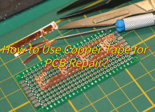
LED bulb MCPCB is a metal-based circuit board designed to support and cool LED chips. It replaces standard PCBs in LED bulbs to handle high heat. Aluminum MCPCB is the most common type used in LED bulbs. It offers excellent heat transfer, improves bulb lifespan, and ensures stable lighting in compact spaces.
What is LED bulb MCPCB?
LED Bulb MCPCB is a specialized type of circuit board designed to handle the unique demands of LED lighting. Unlike regular PCBs, it features a metal baseâusually aluminiumâthat helps manage the intense heat LEDs generate.
In a compact bulb where space is limited, heat can build up quickly. The MCPCB works as a silent protector. It absorbs and transfers heat away from the LEDs, keeping the bulb cool, safe, and long-lasting.
The LED bulb MCPCB doesnât just manage heatâit stabilizes performance. Without it, your bulb might flicker, burn out fast, or even overheat.
Why choose Aluminium MCPCB board for LED bulb?
Aluminium MCPCB boards are the go-to choice for LED bulbs. Why? Because aluminium delivers superior thermal conductivity, low cost, and lightweight properties. It keeps the LED components safe, efficient, and cool under pressure.
When you use an aluminium MCPCB board for LED bulb, youâre choosing durability without sacrificing design. Aluminium is also recyclable, which makes it a greener option for sustainable lighting. Plus, it resists wear and corrosion, helping your bulb last longer, even in tough environments like factories or outdoors.
This material is also easier to shape and fit into bulb housings. That makes the manufacturing process smoother and faster, which leads to better quality and more affordable LED lighting for everyone.
How is LED bulb MCPCB different from regular PCBs?
Most traditional PCBs use FR4, a fiberglass-based material that canât handle high heat well. Regular PCBs might work in low-temperature electronics, but LED bulbs are a different story.
LEDs emit heat as they shine. If you use a regular PCB, the heat stays trapped, slowly damaging the LEDs. Over time, this leads to reduced brightness, shorter lifespan, and possible safety issues.
On the other hand, LED bulb MCPCBs, especially those made with aluminium, are heat masters. They move the heat away from sensitive components, improving efficiency and making your bulb last longer.
What is AC DC LED bulb MCPCB?
It refers to a special MCPCBused in bulbs that can operate with both alternating current (AC) and direct current (DC). These boards are equipped with additional circuitry to manage voltage conversion and stabilize current flow.
It can be used in various settingsâhomes, offices, emergency lighting, solar lighting.
An AC DC LED bulb MCPCB is ideal for markets where power sources vary. It keeps performance consistent, reduces the chance of failure, and expands the bulbâs usability.
How does LED bulb driver circuit work?
The LED bulb driver circuit is usually integrated into the MCPCB itself or connected to it. It converts high-voltage AC power into a lower-voltage DC current that LEDs need. It also stabilizes voltage fluctuations, protecting sensitive components.
Driver circuit controls the electrical input to the LEDs. It ensures the current stays steady and within safe limits. These circuits help cut down on energy waste, reduce heat, and extend the life of your bulb.
What is LED bulb MCPCB used for?
LED bulb MCPCBs are used in light bulbs. But thereâs more to it.
Theyâre essential in any LED lighting that demands compact size, heat management, and long-term reliability. This includes:
Residential LED bulbs
Commercial ceiling lights
Emergency lighting
Solar-powered lamps
Automotive LED lights
Industrial high-bay lights
These boards can be customized in shape, layer count, and thickness to match specific lighting needs. From a tiny reading lamp to a streetlight, MCPCBs play a central role.
Can 15 watt LED bulb MCPCB handle heat well?
15 watt LED bulb MCPCB is typically made with thicker aluminium and better thermal vias. These help spread heat across a larger surface and transfer it efficiently to the bulbâs housing.
With smart layout and quality soldering, it can easily handle the thermal load. The key lies in choosing the right materials and thickness. At EBest Circuit (Best Technology), for example, we design each LED bulb MCPCB to match the wattageâs thermal needs, so it performs without breaking a sweat.
Is 50 watt LED bulb MCPCB durable enough?
50 watt LED bulb MCPCB usually include larger heat sinks and thicker copper layers to carry higher currents. It powers high-brightness lighting and must handle serious heat. They also feature stronger insulation layers to prevent breakdown over time.
Used in high-power LED floodlights, industrial lamps, or streetlights, 50 watt LED bulb MCPCBs are built for endurance. Their design ensures thermal resistance, electrical stability, and rugged durability.
What is the difference between MCPCBs for LED bulbs of different watt?
As the wattage goes up, the complexity and strength of the board must increase. Hereâs how they differ:
9W LED bulb MCPCB: Thin, compact, ideal for home lighting.
12W LED bulb MCPCB: Slightly thicker, handles more heat, often used in ceiling lights.
15W LED bulb MCPCB: Needs improved heat sinking, used in brighter spaces.
18W LED bulb MCPCB: Stronger thermal design, may require larger base.
50W LED bulb MCPCB: Built like a tank. Thicker copper, extra thermal vias, more robust structure.
Also, pricing varies. A 9W LED bulb MCPCB price is lower. A 50 watt LED bulb MCPCB will cost more due to the materials and design complexity.
Conclusion:
LED bulb MCPCB combines heat dissipation, power and performance in one compact circuit board. Choosing an aluminum MCPCB board for LED bulb gives you better thermal control, longer life, and safer operation.
Want custom or bulk LED bulb MCPCBs tailored to your project? Reach out to sales@bestpcbs.com
China IMS PCBÂ offers a new level of thermal performance compared to standard PCB, and that is why it has become the top choice for power electronics and LED applications. But is it always better than traditional PCB? Let’s explore the answer in detail.
EBest Circuit (Best Technology) is a reliable IMS PCB manufacturer and turnkey PCB Manufacturing service provider in China. We cater IMS PCB prototype, mass production, IMS PCB SMT assembly, and box build services in a truly free market. If you are looking for a decent quality China IMS PCB factory that is equipped with the cutting-edge manufacturing equipment and inspection apparatus, complete QC system, and strict test means, then EBest Circuit (Best Technology) is the way to go. For specific IMS in PCB questions and inquiries, please email us from our Contact Us page on the website.
What Does China IMS PCB Mean?
China IMS PCB stands for Insulated Metal Substrate PCB, manufactured by Chinese IMS PCB manufacturers. IMS PCB, also known as thermally conductive PCB, thermal PCB board, thermal Management PCB, and IMPCB.
In China IMS PCB, the circuit is built on a metal base, usually aluminum or copper. The core of IMS technology lies in its thermally conductive yet electrically insulating layer, which sits between the metal base and the copper circuit layer. This dielectric is usually filled with ceramic particles, allowing it to conduct heat efficiently while keeping the electrical signals isolated. The thermal conductivity of this insulating layer typically ranges from 1 to 3 W/m·K, but some advanced materials used in high-end applications can exceed 5 W/m·K. Besides ceramic-filled materials, some IMS boards use advanced polymer-based insulating layers, which offer flexibility in thickness and can be tailored for specific thermal or electrical needs.
This design improves heat dissipation and structural strength. Unlike regular PCB made of FR4 material, IMS boards handle higher power loads with ease. Many China-based factories now focus on IMS production due to the growing demand in automotive, LED, and industrial sectors.
Who Are the Best China IMS PCB Manufacturers?
Choosing the right manufacturer can affect quality and cost. EBest Circuit (Best Technology) is a trusted name for China IMS PCB. We follow IPC standards, apply MES systems for traceability, and offer real-time quality monitoring. Our strength lies in custom thermal design, fast delivery, and flexible order sizes. Other reputable suppliers include A-Tech Circuits and JLCPCB.
What Is China IMS PCB Price?
The price of China IMS PCB depends on more than just size. Materials, design complexity, and special processing all affect the cost. Below is a detailed explanations to help you understand the key pricing factors.
1. Material Type
Aluminum-Based IMS PCB: This is the most common choice due to its balance of cost and thermal performance. A 1.5mm thick aluminum IMS board typically costs around $0.20 per square inch.
Copper-Based IMS PCB: Provides better thermal conductivity and durability, especially for harsh environments, but usually costs 1.5 to 2 times more than aluminum-based boards.
Dielectric Layer: Thermal insulation materials filled with ceramic or polymer vary in price. High-conductivity dielectrics (>3 W/m·K) cost more than standard ones.
Specialty Fillers: Advanced options like boron-filled dielectrics offer improved thermal stability but increase material cost by 10%â25%, depending on the formulation.
2. Thickness and Size
Thicker Metal Cores (>2mm): These require more raw material and longer machining time, raising both material and processing costs.
Larger Panel Size: Increases raw material use and slows production speed, slightly raising the per-unit price.
3. Layer Count
Single-Layer IMS PCB: Most cost-effective; ideal for heat-sensitive, low-complexity designs.
Double or Multi-Layer IMS PCB: Involve complex bonding and precision drilling, which increases both material cost and labor. These are 10%â30% more expensive than single-layer versions.
4. Surface Finish and Special Processing
Surface Treatments: Options like ENIG or OSP add to the price. ENIG, for instance, offers better corrosion resistance but is costlier than basic HASL finishes.
Diamond Cutting: Needed for clean edge finishes on thicker metal cores. This adds a processing premium of around 5%â10%.
Solder Mask Type: High-temperature solder masks or UV-curable masks may also increase pricing slightly.
5. Comparison to FR4 PCB
On average, China IMS PCB cost is 20%â50% higher than standard FR4 PCBs of similar dimensions.
For example, a 1.5mm FR4 board might cost $0.10 per square inch, but lacks the heat handling and strength of IMS.
The additional cost is often offset by the longer lifespan and reduced maintenance of IMS in demanding applications.
6. Order Volume
Prototype Orders: Most Chinese suppliers allow no MOQ and quick turnaround for prototypes.
Small Batch Orders: May include engineering setup fees ($20â$50) for design validation and tooling.
Mass Production: Larger orders reduce cost per unit. Many suppliers offer tiered pricing, with better rates for orders over 1,000 units.
7. Value in High-Power Applications
IMS PCBs perform better under thermal stress, so they reduce failure rates in power electronics, LEDs, and automotive systems.
The higher upfront cost often pays off through longer service life and fewer field failures.
In summary, when assessing China IMS PCB price, itâs important to consider material type, layer count, special processing like boron-filled insulation, and order size. While IMS boards cost more than FR4, they deliver better thermal performance and reliability, especially in power-hungry designs. Over time, this can reduce maintenance costs and improve product lifespanâmaking IMS a smart investment for many applications.
Why Do I Need China IMS PCB?
Thermal control is key in electronics. IMS in PCB helps to reduce heat buildup, which protects components and maintains performance. Applications such as LED lighting, power supplies, and EV chargers often generate excess heat. In these cases, using China IMS PCB can prevent failure. Also, the mechanical strength of metal-core boards improves vibration resistance. If your design needs better heat flow, IMS is worth the extra cost.
What Is the Difference: China IMS PCB vs PCB?
The main difference is in material and thermal performance. Standard PCB uses FR4, a fiberglass material, while IMS uses metal cores. FR4 PCBs have low heat conductivity (0.1 to 0.5 W/m·K), but IMS boards range from 1 to 12 W/m·K. This makes China IMS PCB ideal for high-power systems. However, IMS is less flexible in multilayer designs and costs more. On the other hand, FR4 is cheaper and easier for complex routing. So the choice depends on the application.
What Are the Pros and Cons for China IMS PCB vs PCB?
Here is a clear view of the pros and cons:
Pros of China IMS PCB
Superior Thermal Control:Â Prevents overheating and extends component life.
High Mechanical Strength:Â Reduces warping and improves durability in harsh environments.
Ideal for Power Applications:Â Handles high currents with minimal heat rise.
Better Heat Flow:Â No need for thermal vias, direct heat spread through metal core.
Cons of China IMS PCB
Higher Cost:Â Material and tooling cost more than FR4 PCB.
Limited Layer Count:Â Not suitable for complex, multilayer circuits.
Thermal Stress Risks:Â Poor bonding or design can cause delamination in low-quality boards.
Why Choose EBest Circuit (Best Technology) as Your Dependable IMS PCB Manufacturer?
At EBest Circuit (Best Technology), we understand the headaches customers face when sourcing China IMS PCB. Poor thermal design, weak bonding, and long lead times can all lead to delays and failure. We solve these with:
Thermal Simulation Support:Â We offer thermal modeling to guide your design and prevent hotspots.
Advanced Materials:Â Our boards use hybrid cores and optimized dielectrics to improve heat flow and reduce stress.
Reliable Production:Â Our MES system ensures traceability, and all boards pass IPC-compliant testing like thermal cycling. And all the fabrication process is in line with ISO 9001, ISO 13485, IATF 16949, AS9100D, UL, REACH, RoHS.
Flexible Orders:Â We support no-MOQ prototypes and offer higher quality mass orders with short lead time.
Application-Specific solutions: As we have 19 years of âaccumulation in the rapidly evolving world of electronics, you will get the benefits from our rich experience and technical knowledge to help you choose between FR4/IMS and get an ideal solution.
Expert Support:Â From quoting to delivery, our engineers assist you in every step, ensuring clear communication and fast turnaround.
Our clients appreciate not only our quality but also our commitment to problem-solving. With China IMS PCB, success is in the details, and we handle those with care.
To sum up, China IMS PCBÂ brings real advantages in heat management, mechanical strength, and durability. While it comes at a higher cost, the benefits often justify the price in high-power settings. However, design and manufacturing skills make a significant difference.
Thatâs why working with EBest Circuit (Best Technology) gives you âunmatched precision, reliability, and cutting-edge solutions tailored to your needs.â Our thermal modeling, strict quality control, and fast delivery remove the usual risks. So if you need reliable IMS PCB solutions, contact us today for a quote. Our engineers are very responsible, caring, professional, experienced, and knowledgeable. They were always available to discuss your case and have returned your phone calls in a timely manner. Please discuss your full requirements with our teams at +86-755-2909-1601 or sales@bestpcbs.com.
China MCPCB LED board suppliers are now offering more flexible, fast, and dependable solutions to global lighting brands. Whether you’re a startup or scaling up, choosing the right Chinese PCB manufacturer makes a real difference. In this blog, weâll go through the core questions customers usually ask and how a reliable partner like EBest Circuit (Best Technology) can simplify the buying experience.
EBest Circuit (Best Technology) provides high-quality China MCPCB LED boards and delivers trustworthy and reliable LED PCB assembly services to the very large market. We are most trustworthy in optimizing our supply chain, offering high-mix MCPCB LED boards selections, achieving high yield, maintaining a stable manufacturing process, ensuring short lead times, providing fast after-sales service, and preserving quality consistency.
There are some well-known brands that make a long-term relationship with us. And we still maintain a high customer retention rate. If you would like to inquire about any MCPCB LED boards, our team is always available to discuss your project details by phone or email and provide viable solutions. Our phone number is +86-18923412995. Email sales@bestpcbs.com is also ok. You can also talk to us online via this link.
Who Provides China MCPCB LED Board?
There are hundreds of Chinese PCB manufacturers, but only a few specialize in MCPCB LED boards. These boards, made with metal core bases like aluminum or copper, need professional manufacturing. Reliable suppliers like EBest Circuit (Best Technology) focus on high-precision drilling, consistent thermal conductivity, small-batch support, lead time reduction, and complete material traceability. Our strength lies in combining fabrication with engineeringâso you donât just get a board, you get a well-designed, ready-to-use solution.
What Is China MCPCB LED Board Price?
China MCPCB LED board price depends on size, copper thickness, layer count, and surface finish. Smaller boards with standard specs may cost as low as $0.20 per piece. More advanced types like high-wattage copper-core boards cost more. But what truly matters is not just low pricingâitâs the value. EBest Circuit (Best Technology) offers reasonable pricing thanks to bulk raw material sourcing and automatic MES tracking. We help you control costs while meeting strict technical demands.
What Are the Advantages of Buying MCPCB LED Board from Chinese PCB Manufacturers?
There are clear benefits of working with Chinese PCB manufacturers:
Speed:Â Fast quoting, short lead times, and on-time shipping.
Cost efficiency:Â Lower labor and material costs reduce your expenses.
Technical support: Experts help you with MCPCB design suggestions before production.
Turnkey service:Â From prototyping to mass production and assembly.
EBest Circuit (Best Technology) stands out with in-house DFM checking, thermal simulation tools, and a full testing line including flying probe, AOI, and X-ray inspection. We are a qualified MCPCB LED board factory, compliant with ISO 9001, ISO 13485, IATF 16949, AS9100D, UL, REACH, RoHS. That ensures reliability, not just savings.
12V MCPCBs are stable, easy to integrate, and safe for both indoor and outdoor use. EBest Circuit (Best Technology) supports customization in wattage, dimensions, and surface coating so customers can build to spec with no worries.
Where to Get MCPCB Design?
MCPCB design plays a key role in thermal control and product life. If the layout is poor, LEDs overheat or fail. Many buyers donât have in-house engineers, so they turn to manufacturers. EBest Circuit (Best Technology) provides one-on-one design guidance with quick CAD reviews and thermal modeling support. Whether you want a single-layer or complex structure, our team helps optimize the circuit to match your exact requirements.
How to Ensure Quality of MCPCB Board Buy from Chinese PCB Manufacturers?
When you buy an MCPCB board from a Chinese supplier, you’re not just looking for specs on paperâyou want dependable and repeatable quality. At EBest Circuit (Best Technology), we follow strict IPC standards and use a MES system to track every production step. Full material traceability is built into our process to avoid mix-ups and ensure consistency.
We understand that many buyers have had issues beforeâpoor plating, misaligned drilling, or weak thermal bonding. To address these concerns, we carry out a full range of quality checks, including:
100% electrical testing to verify open and short circuits
Solderability tests to confirm pad surface finish integrity
Insulation resistance measurement to ensure safety in high-voltage applications
Thermal aging tests, following a standard of 85°C at 85% RH for 1000 hours, to assess long-term stability under harsh environments
Thermal resistance (Rth) tests, critical for MCPCB performance, to verify heat dissipation efficiency
X-ray inspection, especially for boards with buried vias or inner layer bonding, to detect voids or misalignment inside the structure
We also provide complete test reports for your approval before final shipment. This way, you know exactly what quality level you’re getting.
Why Choose EBest Circuit (Best Technology) for Your Dependable China PCB Manufacturer?
EBest Circuit (Best Technology) doesnât just sell boards. We solve problems. Many customers come to us because they struggled with vague communication, poor DFM checks, or unstable lead times elsewhere. Hereâs how we help:
Fast response:Â Quotes in 4 hours, engineering reply in 12 hours.
Clear tracking:Â MES system shows real-time production status.
Certifications:Â ISO 9001, IATF 16949, ISO 13485, and AS9100D.
Flexibility:Â Low MOQ, urgent builds, and trial runs supported.
Full transparency:Â From stack-up to material sourcing.
One-stop service: We provide material procurement, MCPCB design, MCPCB prototype, mass production, and MCPCB assembly service under one roof.
Customization: No matter whether you need single-layer MCPCB, two-layer MCPCB, multi-layer MCPCB, COB MCPCB, double-sided MCPCB, or IMS PCB, we present support without any MOQ.
We take quality control seriously. For example, our X-ray checks verify LED solder joints inside aluminum MCPCBs. Our team supports multiple marketsâautomotive, aerospace, medical, and general lighting. You can always reach out to our teams for any concerns. Our sales engineers possess strong technical knowledge, allowing them to address your issues directly. When you encounter difficulties, our sales team will provide you with the appropriate answers and solutions without making you wait for responses from the engineers.
To summarize, if youâre tired of delays, unclear specs, or inconsistent product quality, then itâs time to try a new partner. At EBest Circuit (Best Technology), we offer not just China MCPCB LED board manufacturing but a whole process of support. From smart design to final shipment, weâre here to back you up. For more information or if you would like to send us any inquiry, please send us an email through the contact form at the bottom of our Contact Page.
MCPCB is mainly made of copper foil, a dielectric layer, and a metal core. The copper layer handles current flow and signal transmission. The dielectric layer sits beneath it, offering electrical insulation while allowing heat to pass through. At the base, the metal coreâusually aluminum or copperâacts as a heat sink. Aluminum is lightweight and cost-effective, while copper delivers better thermal performance.
Unlike standard FR4 boards, which use fiberglass, MCPCB boards use metals like aluminum, copper, or even a mixture. That metal layer acts as a heat sink, pulling heat away from components.
This makes MCPCB ideal for LED lights, high-power electronics, and automotive systems. Theyâre strong, thermally efficient, and can take a beating.
What is the structure of Mcpcb?
The basic structure of an MCPCB is relatively simple, but each layer plays a critical role. It usually consists of three key layers:
Copper Circuit Layer: The top layer for routing signals, just like in traditional PCBs. Itâs often thicker in MCPCBs to handle high currents.
Dielectric Layer: This sits between the copper and the metal base. It provides electrical insulation while enabling heat transfer.
Metal Core Base: Usually made of aluminum, copper, or a hybrid alloy. This is the foundation that supports the board and helps spread heat efficiently.
Some MCPCBs even feature multi-layer stackups, combining several circuit and dielectric layers with a central metal core.
What are the materials in Mcpcb?
The most commonly used materials in MCPCB manufacturing are aluminum, copper, and steel alloys. This is the heart of the MCPCB.
Aluminum: Most cost-effective and widely used. Lightweight, corrosion-resistant, and a good thermal performer.
Copper: Offers better thermal conductivity, but it’s heavier and more expensive.
Stainless Steel or Alloys: Used in high-strength or custom applications.
Each MCPCB raw material brings different strengths. Picking the right one is about balancing performance, cost, and durability.
What are the differences between MCPCBs of different materials?
Different MCPCB materials impact cost, conductivity, weight, and reliability.
Aluminum MCPCB: Most popular for LED applications. It offers decent conductivity and costs less. Itâs also easy to process and lightweight.
Copper MCPCB: Ideal for high-performance needs. With thermal conductivity up to 390 W/mK, itâs a powerhouse. But itâs heavier and more expensive.
Steel alloys MCPCB: These combine metals for specific thermal and mechanical needs. For example, aluminum-copper blends.
Choosing the right type depends on your prioritiesâis it price, heat handling, weight, or ruggedness?
How to make mcpcb?
The MCPCB manufacturing process requires high precision. Here’s how it typically works:
Metal Base Preparation: The selected metal core (usually aluminum or copper) is cleaned and prepared for lamination.
Dielectric Application: A thin dielectric layer is applied using lamination or coating methods. This layer needs to be uniform to maintain consistent heat flow and insulation.
Copper Lamination: A copper foil is laminated on top of the dielectric. The thickness varies depending on current needs.
Circuit Imaging and Etching: The copper layer is printed with the circuit design and etched to form the signal paths.
Solder Mask and Surface Finish: Protective coatings are applied to prevent oxidation. Then surface finishes like OSP, ENIG, or HASL are added for solderability.
Drilling and Routing: Holes are drilled, and the board is routed to its final shape. V-cuts or scoring may be added for separation.
Testing: Every board is electrically and visually tested to ensure it meets performance standards.
The result is a durable, heat-efficient PCB ready for demanding environments.
What is the difference between FR4 and Mcpcb?
FR4is a glass-reinforced epoxy laminate used in standard PCBs. Itâs strong, affordable, and widely available.
MCPCB, by contrast, can handle much higher thermal loads. Thanks to the metal core, it can draw heat away from critical components. That means longer lifespan, better performance, and fewer thermal failures.
Another difference is mechanical. MCPCB boards are more robust and rigid, while FR4 can be more fragile under stress or heat. The trade-off? FR4 is cheaper. But for high-power or LED uses, MCPCB is well worth the investment.
What is the difference between ceramic PCB and Mcpcb?
Both ceramic PCBs and MCPCBs excel in thermal management. But their core material and applications differ.
Ceramic PCBs use ceramic substrates like aluminum oxide or aluminum nitride. These have excellent electrical insulation and can withstand high temperatures. Theyâre common in aerospace and medical electronics.
MCPCBs use a metal core with a dielectric layer. They balance thermal efficiency and cost, making them ideal for mass-market products like LED lighting.
Ceramic PCBs are better for ultra-high-performance, but MCPCBs offer a smart solution for most thermal challenges at a more affordable cost.
How thick is the copper in Mcpcb?
The copper layer thickness in MCPCB can range from 1 oz to 6 oz (35ÎŒm to 210ÎŒm). Thicker copper means:
Better current carrying capacity
Improved durability
Enhanced thermal management
For LED applications, 1â2 oz is common. High-power systems may need 3 oz or more. It all depends on the current load and thermal performance needed.
What is the thermal conductivity of Mcpcb?
One of the most important specs of an MCPCB is its thermal conductivity, usually measured in W/mK.
The dielectric layer in standard MCPCBs typically ranges from 1.0 to 3.0 W/mK.
High-end materials may reach up to 10 W/mK or more.
The metal base (aluminum or copper) naturally has higher thermal conductivity. Copper can hit 390 W/mK, while aluminum is around 200 W/mK.
High thermal conductivity means faster heat transfer, lower operating temperatures, and greater reliability over time.
What is the use of Mcpcb?
MCPCB is used where heat is the enemy. Youâll see it in:
LED lighting modules (street lamps, automotive lights, flashlights)
Power converters
Motor controllers
Telecom base stations
Automotive electronics
Industrial machines
Why? Because MCPCB keeps everything cool. When heat drops, performance goes up, and failures go down.
Conclusion:
If your project demands high heat resistance, reliability, and space efficiency, MCPCB material is the key. Whether it’s for LED lighting, automotive systems, or high-performance power applications, the right mcpcb material makes all the difference.
Looking for a reliable MCPCB manufacturer? Email us at sales@bestpcbs.com
How to design20 oz copper PCB for high current? Let’s explore thickness, specifications, benefits, application and design guideline for 20 oz copper PCB.
Are you worried about these problems?
PCB circuits are prone to overload and burn in high current scenarios.
The heat dissipation solution takes up space and is expensive.
The yield rate of thick copper plate processing fluctuates greatly.
The services EBest Circuit (Best Technology) can provide:
The 20oz ultra-thick copper foil design has a current carrying capacity that is 3 times that of conventional PCBs. It can stably carry 150A continuous current through thermal simulation verification.
The patented copper-based composite structure and built-in heat conduction channel realize PCB self-heating, saving 40% of the cost of peripheral heat dissipation components.
The unique step-by-step pressing process, combined with full-process quality control, ensures that the batch production yield rate is stable at more than 95%.
Welcome to contact EBest Circuit (Best Technology) if you have any inquiry for copper PCB: sales@bestpcbs.com.
What Is a 20 oz Copper PCB?
A 20 oz copper PCButilizes a 700ÎŒm-thick copper layer (equivalent to 20 ounces per square foot), significantly exceeding standard copper weights to achieve exceptional electrical performance. This extreme copper thickness minimizes resistive losses (IÂČR heating) while enabling current handling capabilities exceeding hundreds of amperes, making it essential for high-power systems requiring stable operation under intense loads.
Its substantial copper mass provides superior thermal conductivity (>380 W/m·K), efficiently dissipating heat toward heatsinks or enclosures to maintain operating temperatures within safe limits. Fabrication demands specialized processes like stepped lamination and high-temperature resins to prevent delamination, ensuring structural integrity during repeated thermal cycles. These boards serve critical roles in electric vehicle charging systems, industrial power converters, and energy distribution infrastructure where reliability under sustained high loads is non-negotiable.
How Thick Is 20 oz Copper PCB?
The thickness of a 20 oz copper layer in a PCB is approximately 700 micrometers (ÎŒm) . This measurement is derived from the industry standard where 1 ounce (oz) of copper per square foot equals roughly 35 ÎŒm in thickness, utilizing copper’s density and unit conversion principles. Due to manufacturing tolerances, the actual copper thickness may vary by ±10%, resulting in a typical range of 630 ÎŒm to 770 ÎŒm for 20 oz copper PCBs.
20 oz Copper PCB Specifications
Parameter
Specification
Copper Thickness
700Όm (20 oz) ±10%
âCurrent Capacity
100A+ continuous
Base Material
1-3mm thick copper core (99.95% purity)
âThermal Conductivity
400W/(m·K) (copper core)
Insulation Layer
50-100ÎŒm ceramic (AlâOâ/AlN), >3kV breakdown
âMin Trace Width
12mil (0.3mm)
Benefits of 20 oz Copper Base PCB
Extreme Current Handling â Supports 100A+ continuous current (3x standard PCBs), ideal for high-power applications like EV chargers and industrial inverters.
Superior Thermal Management â Copper core dissipates heat 60% faster than aluminum, reducing hotspots and extending component lifespan.
Space-Saving Design â Thick copper (700ÎŒm) allows narrower traces (12mil vs. 6mm for equivalent current), saving PCB area.
High Reliability â Resists thermal cycling fatigue, 3x longer lifespan in high-temperature environments vs. standard PCBs.
Lower Resistance â Pure copper base reduces conductive losses by 40%, improving energy efficiency.
High-Frequency Performance â Smooth copper surface (Ra<0.5ÎŒm) minimizes signal loss for RF/5G applications.
Mechanical Strength â Copper core prevents warping under heavy components (e.g., IGBT modules).
High-Power Electronics â Ideal for EV charging systems, industrial motor drives, and power converters requiring minimal resistance and efficient heat dissipation.
RF & Telecommunications â Best for 5G base stations and satellite communication equipment where signal integrity and thermal stability are crucial.
Heavy-Duty Power Switching â Suitable for welding machines, server power supplies, and UPS systems handling extreme current surges.
High-Brightness LED Systems â Used in stadium lighting and industrial LED arrays where active cooling is necessary to maintain performance.
Automotive Power Modules â Optimal for EV inverters and battery management systems needing compact, high-current designs.
High-Temperature Industrial Equipment â Applied in machinery where prolonged thermal cycling and reliability are key factors.
What Is Difference between 16 oz and 20 oz Copper PCB?
Comparison Aspect
16 oz Copper PCB
20 oz Copper PCB
âCopper Thicknessâ
~560 ÎŒm
~700 ÎŒm
âCurrent Carrying Capacityâ (at same trace width)
Handles high currents (e.g., ~80A for 10mm width)
âThermal Management
Good heat dissipation, suitable for moderate-power apps
Superior heat spreading, minimizes hotspots by 15-20%
âSpace Efficiencyâ (trace width for same current)
Requires wider traces (e.g., 6mm for 30A)
Enables narrower traces (e.g., 4.8mm for 30A), saving PCB area
Manufacturing Cost & Difficulty
Higher cost than standard PCBs, moderate etching challenges
Highest cost due to complex etching and material use
Applications
Industrial motor drives, UPS systems
EV fast chargers, server power supplies (>500A surges)
Plane Layers: Use full-layer planes for currents >30A (lower impedance, better heat spread).
2. Thermal Management
Via Arrays: Place â„0.3mm vias under power devices (pitch â€1.5mm). Fill with thermal paste to connect to bottom copper, cutting thermal resistance by >50%.
Exposed Copper: Remove solder mask for direct air cooling (2â3Ă heat dissipation). Apply ENIG/HASL for oxidation resistance.
Embedded Copper: For >50A, embed 1.5mm copper blocks in FR4 layers (reduces local temps by â„30°C).
3. Layer Stackup
Multilayer Structure: “Sandwich” stackup (power layer â insulating layer â 2 oz copper + 1mm aluminum). Inner layers use stepped copper (0.5â4 oz) to reduce Z-axis stress.
Prepreg: High-resin (e.g., 2116) for 85%+ fill. Board edges reinforced with epoxy slots (30% stronger).
4. Manufacturing
Etching/Plating: Use LDI for 3/3mil traces; pulse plating for â„25”m hole copper (uniformity >90%).
Lamination: Pre-press 180°C/40min/15kg/cmÂČ; full press 200°C/90min/25kg/cmÂČ; cool â€3°C/min.
Turnkey Solutions â Full-service PCB manufacturing from design to delivery, accelerating your productâs time-to-market.
ISO 14001/ISO 13485 certification: medical/automotive customers are exempt from secondary testing, and compliance costs are reduced by 30%.
Free DFM (Design for Manufacturability) Analysis: Optimizes PCB layouts to reduce material waste, lower production costs, and avoid late-stage design revisions.
Rigorous quality control: directly reducing your maintenance costs by 40% while extending product lifespan.
If you have any request for copper base PCB, welcome to contact us to get a free quote: sales@bestpcbs.com.
Data endorsement: JEDEC standard thermal resistance test report is provided for each batch.
Scenario design: 1.2mm ultra-thin heat spreader/multi-layer stacking structure, actual measurement reduces the temperature of key nodes by 20â.
Feel free to contact us now if you have any inquiry for aluminum PCB: sales@bestpcbs.com.
What Is the Thermal Resistance of Aluminum PCB?
The thermal resistance of analuminum PCB typically ranges from 0.5 to 3.0°C/W, depending on its construction. Key factors include the thickness of the dielectric layer (50â200ÎŒm), the thermal conductivity of the aluminum base (160â200W/m·K), and the copper circuitry layout. Compared to FR4 PCBs (10â20°C/W), aluminum substrates offer 5â10Ă better heat dissipation due to their superior thermal conductivity. For high-power applications, designs with ceramic-filled dielectrics or hybrid materials can achieve thermal resistances below 0.2°C/W. Performance varies with aluminum alloy type (e.g., 6061 vs. 1060) and surface treatments like anodizing.
How to Choose the Thermal Resistance Type of Aluminum PCB?
1. Prioritize power requirements by thermal resistance value
Low thermal resistance type (<0.5â/W): Suitable for high power density scenarios (such as LED modules >5W/cmÂČ, electric vehicle power modules). Although the unit price is high, it can reduce the junction temperature by more than 40â, significantly extending the life of the device.
Medium thermal resistance type (0.5-1â/W): Used for medium power equipment (such as household appliance power supplies, industrial controllers), balance heat dissipation performance and cost, and the thickness of the insulation layer is usually controlled at 80-100ÎŒm.
2. Optimize cost performance by structural selection
Traditional FR-4 composite type: Select when only basic heat dissipation is required (such as low-power LED light strips), the cost is 40%-60% lower than that of dedicated aluminum substrates, but the thermal resistance is >1â/W.
Magnetic control sputtering technology type: Suitable for high-frequency and high-temperature applications (such as 5G base station RF modules), the insulation layer is thinner (50-75ÎŒm), and the thermal resistance is as low as 0.1â/W, but the process cost increases by 20%-30%.
Multilayer thermal conductive structure type: The first choice for complex systems (such as server power supplies). The hot spots are dispersed through multi-layer thermal conductive dielectrics. The thermal resistance can be controlled at 0.3-0.8â/W, which is suitable for multi-chip integrated design.
3. Cost-sensitive alternatives
Hybrid design: Aluminum substrate is used for the core high-heat area (such as the CPU cooling area), and FR-4 is used for the peripheral circuit, which reduces the overall cost by 25%-40%.
Copper foil thickness optimization: 1oz copper foil meets most scenarios, and 3oz copper foil (105ÎŒm) is only used for ultra-high current to avoid excessive design and increase board costs.
Tips: First determine the allowable temperature rise through thermal simulation, and then compare the thermal resistance-price curves of different models, and give priority to the lowest cost solution that meets the temperature control requirements.
How to Calculate Thermal Resistance of Aluminum PCB?
The thermal resistance (RΞ) of aluminum PCBs is calculated by combining material and structural parameters: RΞ = (Lâ/(kâ·Aâ)) + (Lâ/(kâ·Aâ))
L: Thickness of each layer (meters)
k: Thermal conductivity (W/(m·K))
A: Heat dissipation area (square meters)
The aluminum substrate layer (kââ1-5 W/(m·K)) and insulating layer (kââ0.5-3 W/(m·K)) contribute additively to thermal resistance, while the copper layerâs resistance is typically negligible. Ensure unit consistency and account for the series relationship of heat dissipation paths in practical calculations.
What Factors Affect the Thermal Resistance of Aluminum Substrate?
Material Thermal Conductivity â Lower conductivity in the dielectric layer increases thermal resistance due to reduced heat transfer efficiency.
Layer Thickness â Thicker dielectric layers raise resistance, while thinner aluminum bases may limit heat spreading capabilities.
Interface Quality â Poor contact surfaces between aluminum and dielectric layers add interfacial thermal resistance, impacting overall performance.
Structural Elements â Features like thermal vias or hybrid composites (e.g., with carbon nanotubes) enhance heat dissipation and lower resistance.
Environmental Factors â Moisture absorption and high operating temperatures degrade thermal properties, increasing resistance in humid or extreme conditions.
Surface Treatments and Coatings â Protective or conductive finishes alter heat flow, reducing resistance if optimized for thermal management.
Density and Porosity â Higher density dielectric materials improve insulation but may increase resistance, whereas porosity can trap air and worsen performance.
How to Design to Reduce the Thermal Resistance of Aluminum PCB?
Design Strategies to Reduce Aluminum PCB Thermal Resistance:
Optimize Dielectric Layer: Use thinner, high-thermal-conductivity insulation (e.g., graphene-filled or ceramic-filled prepreg) to reduce heat transfer barriers.
Increase Metal Core Thickness: Thicker aluminum substrates (e.g., 2.0mm vs. 1.0mm) enhance lateral heat spreading.
Maximize Copper Coverage: Use thicker copper traces (â„2oz) and expand ground/power planes to boost heat dissipation.
Add Thermal Vias: Place arrays of small, closely spaced vias under high-power components to channel heat to the aluminum layer.
Improve Component Layout: Position heat-generating parts centrally over the aluminum core and avoid clustering.
Capture temperature curves at high speed (â„100Hz).
Derive thermal resistance via exponential fitting: RΞ = (T_max-T_ambient)/Power
4. Thermal Imaging Verification
Use a calibrated infrared thermal imager (accuracy ±2â).
Capture steady-state temperature distribution maps.
Validate hotspot locations against theoretical heat flow paths.
5. Environmental Control Requirements
Temperature: 25±1â (forced air cooling requires airflow velocity â€1m/s).
Humidity: 45±5%RH.
Chamber volume â„1mÂł to minimize boundary effects.
6. Data Processing Standards
Average results from â„3 repeated tests.
Maximum allowable deviation: ±5% for steady-state method, ±8% for transient method.
Exclude abnormal data from nonlinear temperature rise phases.
7. Special Notes
For aluminum substrates with thickness â„1.5mm, additional lateral thermal resistance testing is recommended. Multipoint temperature measurements should be conducted to evaluate thermal diffusion performance.
The test report must include thermal resistance values, testing conditions, equipment accuracy specifications, and thermal imaging attachments.
Why Choose EBest Circuit (Best Technology) as Aluminum PCB Manufacturer?
Precision Thermal Resistance Control: Provide customized thermal resistance values (0.8-5.0°C/W) with ±5% tolerance, ensuring predictable thermal performance for your designs. It can reduce thermal design margins and optimized system costs.
Thermal Performance Verification: Every PCB undergoes JEDEC-standard thermal testing with detailed reports, giving clients certified performance data for reliability compliance.
Application-Specific Thermal Solutions: Tailored designs (e.g., 1.2mm thick for LEDs, multilayer for power modules) lower operating temperatures by 15-20°C. It can achieve longer product lifespan and reduced heatsink costs without redesigns.
24-hour rapid prototyping: shorten the R&D cycle by 50% and accelerate product launch
Competitive & Transparent Pricing â No hidden costs, offering the best value without compromising quality.
Turnkey Solutions â Full-service PCB manufacturing from design to delivery, accelerating your productâs time-to-market.
ISO 14001/ISO 13485 certification: medical/automotive customers are exempt from secondary testing, and compliance costs are reduced by 30%.
Free DFM (Design for Manufacturability) Analysis: Optimizes PCB layouts to reduce material waste, lower production costs, and avoid late-stage design revisions.
Welcome to contact us if you have any request for aluminum PCB: sales@bestpcbs.com. Looking forward to hearing from you soon!
When you look inside an LED lighting product, youâll often find a small but essential component called the LED driver board. This little board plays a big role in making sure your lights work properly and last longer. But what exactly is a LED driver board? How does it work? And how can you tell if one is faulty?
In this blog, weâll walk through everything you need to knowâfrom how it functions to how to test it and where itâs used.
What Is a LED Driver Board?
A LED driver board is an electronic circuit that regulates power to LEDs. LEDs donât work directly from AC power like traditional light bulbs. They need a constant DC current at a specific voltage to operate correctly. Without proper regulation, LEDs may overheat, flicker, or fail prematurely.
The LED driver board manages this power conversion and ensures stable operation. Itâs like a power supervisor, controlling the flow of energy to keep everything within safe limits.
Types of LED Driver Boards
There are several types of LED light driver boards, each serving a different need depending on the application:
1. Constant Current LED Driver Boards
These provide a fixed current to the LEDs while allowing the voltage to vary. They are used in high-power LEDs where current regulation is critical. These boards prevent overdriving the LED, which can cause heat buildup and burnout.
2. Constant Voltage LED Driver Boards
These deliver a fixed voltage output (usually 5V, 12V, or 24V) while the current changes depending on the load. These are commonly used in LED strips or low-power lighting where LEDs are connected in parallel.
3. AC-DC Driver Boards
These convert 120V or 220V AC power from wall outlets into low-voltage DC suitable for LEDs. They include rectifiers and smoothing circuits to provide clean power.
4. Dimmable LED Driver Boards
Some driver boards allow users to adjust brightness. These can use dimming methods like:
TRIAC dimming (phase-cut dimming for residential AC power)
PWM dimming (pulse-width modulation for digital control)
0-10V dimming (analog dimming for commercial lighting)
5. Smart LED Driver Boards
Modern lighting products use intelligent driver boards with features like:
Over-voltage and over-current protection
Temperature monitoring
Wireless control via Bluetooth or Wi-Fi
Programmable lighting behavior
Raw Materials in LED Driver Boards
one of the most important materials of LED driver board is the aluminum LED PCB. Unlike standard FR4 boards, aluminum PCBs use aluminum base as its core, which offers excellent heat dissipation and it is critical for the longevity and performance of LED lighting systems.
Aluminum LED board consists of an aluminum base (like 5052, 6061 aluminum alloy), a thermally conductive dielectric layer, and a copper circuit layer. The aluminum base transfers heat away from the LED components, allowing for higher power densities and improved reliability, especially in high-brightness or high-wattage applications like automotive headlights, floodlights, and industrial lamps.
In addition to the aluminum substrate, LED driver boards use a variety of other materials like copper, electronic components, control ICs, and so on. When all these materials are integrated on an aluminum PCB, the result is a durable, thermally stable driver board that supports long-lasting LED performance even under demanding conditions.
How Does a LED Light Driver Board Work?
A LED light driver board works by converting high-voltage AC power from the mains into low-voltage DC power suitable for driving LEDs. This process typically involves several stages, starting with a rectifier circuit that changes AC to DC, followed by filtering capacitors that smooth the voltage. After that, a switching regulator or linear regulator adjusts the voltage and current to match the LED’s requirements. For constant current drivers, the circuit controls the output current precisely to protect the LED from overcurrent damage. Below is a simple led driver board schematic drawing for reference:
Inside the board, components like MOSFETs, control ICs, and feedback loops work together to maintain stable power output, even if the input voltage or load conditions change. Advanced LED driver boards also include safety features like overvoltage, short-circuit, and thermal protection. Some models support dimming and intelligent control through PWM signals or 0â10V inputs.
What Does a LED Driver Board Do?
In simple terms, the LED driver board ensures your LEDs operate the way theyâre supposed to. Here’s what it really does:
Regulates current and voltage so LEDs donât get too much or too little power
Extends lifespan by preventing overheating and electrical stress
Protects the circuit from power surges, short circuits, and reverse polarity
Improves performance by maintaining consistent light output even when the power supply varies
Without a proper driver board, even the best LED wonât last long.
What Are the Symptoms of a Bad LED Driver Board?
A malfunctioning LED driver board can cause several problems. If your LED light is acting up, here are some signs the driver board might be the culprit:
Flickering light even when power is steady
Dim or unstable brightness
Completely dead light while the power source works
Unusual buzzing sounds from the driver
Overheating of the driver board or the LED
Shortened lifespan of the LED itself
If you notice any of these issues, itâs worth checking the driver before replacing the whole lighting system.
How to Test LED Driver Board with Multimeter?
Before testing, make sure you have a digital or analog multimeter with a fully charged battery. Depending on what youâre testing, you will need to switch between the DC voltage, DC current, and resistance (ohm) settings. Here are the ways to test a led driver board step by step in simple ways:
1. Tools Preparation:
Use a digital or analog multimeter.
Make sure the power is off before testing, unless checking voltage under load.
Know the driverâs rated voltage and current (e.g., 12V, 300mA).
2. Test Output Voltage (DC):
Set the multimeter to DC voltage mode (e.g., 20V or 50V).
Connect the red probe to the driverâs positive output and black to the negative.
Power on the driver. A normal 12V driver should read between 11.5V and 12.5V.
Zero or very low voltage may indicate failure.
3. Test Output Current:
Disconnect the LED from the driver.
Set the multimeter to DC current mode (e.g., 200mA).
Connect the multimeter probes in series with the circuit.
A good driver should output current close to the rated value (e.g., 280â320mA for a 300mA driver).
Burnt rectifier, blown fuse, or shorted components
Low voltage
Faulty regulator IC or degraded capacitor
High ripple
Dried-out electrolytic capacitor
No input power
AC not reaching board or blown input fuse
Flickering LEDs
Intermittent driver output or voltage instability
No continuity
Open trace or failed resistor/fuse
Testing a LED driver with a multimeter is a straightforward but powerful way to troubleshoot lighting systems. If the driver fails any of the above tests, especially with incorrect voltage or current output, it should be replaced to prevent damaging the LED module.
At EBest Circuit (Best Technology), we offer custom LED driver boards, professional testing, and aluminum PCB solutions for LED lighting systems. Whether you’re designing new products or diagnosing a problem in the field, our team is here to support you with precision manufacturing and technical advice.
Medical Devices: Examination lights, operating room lights
Smart Homes: Voice or app-controlled LED lamps
LED Driver Board HS Code
When importing or exporting LED drivers, it is crucial to classify them under the correct Harmonized System (HS) codes to comply with customs regulations and avoid delays or penalties. The HS code varies depending on the specific type of LED product or component involved. Below are common HS codes relevant to LED drivers and related products.
Product Type
Typical HS Code
Description
LED Bulbs/Tubes
8539.50.00
LED replacement light sources (finished bulbs)
LED Driver Power Supplies
8504.40.14
LED driver modules, transformers, power supplies
LED Display Modules
8531.20.00
LED-based digital display units
Complete LED Fixtures
9405.42.90 / 9405.50.00
Finished lighting fixtures and lamps
Note: Always check your countryâs customs database or consult a logistics expert for precise classification, as some driver boards integrated into complete lighting units may have different codes.
FAQs
1. Can I repair a damaged LED driver board?
Yes, if the issue is minor (like a bad capacitor), it can be repaired. But for safety-critical lighting, replacement is often better.
2. Whatâs the difference between an LED driver and a power supply?
An LED driver includes current regulation and protection circuits, whereas a basic power supply may only convert voltage.
3. Is aluminum PCB necessary for LED driver boards?
For high-power lighting, yes. Aluminum PCBs help dissipate heat better than FR-4 boards.
4. How long does a LED driver board last?
Most LED drivers last between 30,000 and 50,000 hours, depending on load and cooling.
5. Can a single driver power multiple LEDs?
Yes, if wired correctly and within the driverâs power capacity. Parallel connections need constant voltage drivers; series connections use constant current drivers.
This is the end of this sharing, if you are interested in LED driver board that used in aluminum base or copper base or FR4 base, you are welcome to contact us. EBest Circuit (Best Technology) is a 19 years experienced PCB & PCB assembly manufacturer in China, we have SMT factory both in China Shenzhen and Vietnam. We are welcome your visiting or any comments.
MCPCB LED refers to a Metal Core Printed Circuit Board designed specifically for LED applications. It uses a metal base, usually aluminum, instead of traditional fiberglass to manage heat from LED chips. Thanks to its excellent thermal conductivity, MCPCB LED is widely used in high-power lighting like automotive lamps, streetlights, and industrial fixtures.
What is the full form of MCPCB LED?
MCPCB stands for Metal Core Printed Circuit Board, and when paired with LEDs, it becomes MCPCB LED. Unlike standard PCBs, which use FR4 (a fiberglass-based material), MCPCBs are designed specifically for high-heat-generating components like LEDs.
Hereâs what sets it apart:
âMetal Coreâ typically refers to aluminum, known for its excellent heat dissipation and durability.
It keeps your LED cool, boosting lifespan and brightness.
It forms the backbone of LED lighting systems like floodlights, strip lights, spotlights, and even vehicle lights.
In short, MCPCB LED is not just a circuit board. It can make your LED lights brighter, longer lasting and better performing.
What is the difference between FR4 and MCPCB?
FR4 is a standard PCB made from fiberglass. Itâs fine for low-heat applications like remote controls or digital clocks.
However, when it comes to LED lights, FR4 struggles. LEDs generate heat. FR4 canât handle it well, which leads to overheating, performance drops, and reduced product life.
Now compare that to MCPCB:
Aluminum core for better thermal conductivity.
Keeps LED junction temperature under control.
Allows for higher power output and longer operation.
Reduces the need for extra cooling systems.
This makes MCPCB LED boards ideal for applications like automotive headlights, industrial luminaires, or any setting where heat is the enemy.
Do LED lights have PCBs?
Absolutely. Every modern LED light you see today has a PCB behind it. In high-power or long-lasting LEDs, manufacturers choose metal-based PCBs, especially aluminum LED MCPCB, because they offer:
Efficient heat dissipation.
Stable mechanical support.
Compact design for space-saving fixtures.
Even LED strip lights, which look thin and flexible, and often, itâs a MCPCB LED strip when used for heavy-duty applications.
Is SMD LED better than COB LED?
both SMD (Surface-Mounted Device) and COB (Chip-on-Board) are great, but they serve different needs.
SMD LED is the most common type, where individual LEDs are mounted on the surface of a PCB. Theyâre versatile, bright, and offer color control. When paired with a LED MCPCB board, they deliver exceptional thermal stability and performance.
COB LED, on the other hand, combines multiple chips into a single module. Itâs great for high-lumen output with fewer shadows and more uniform light.
SMD LED with MCPCB is typically better when:
You need multiple color options.
You want better thermal control.
You plan for high-speed, automated production.
So if youâre thinking about MCPCB LED applications, especially where heat matters, SMD wins most of the time.
How to make LED MCPCB?
Creating a LED MCPCB involves careful layering and expert engineering. Hereâs a simplified breakdown of how it’s made:
Start with the metal base: usually aluminum.
Apply a dielectric layer: an insulating material that resists heat and isolates the conductive traces from the metal core.
Add the copper layer: this is where the circuit paths are etched.
Finish with a solder mask: often white for LED boards to reflect light.
Mount LED chips via SMD process, or bond them directly using thermal adhesive. Every layer is optimized for thermal conductivity, electrical performance, and physical durability.
What are the characteristics of LED MCPCB?
Here are the top characteristics:
High thermal conductivity: it can conduct heat away from LED chips faster than FR4.
Low thermal resistance: ensures the LED runs cooler, which means longer lifespan.
Mechanical strength: ideal for rough environments and industrial usage.
Better light output: thanks to lower heat buildup and reflective solder mask.
Customizability: shape, thickness, hole positioning, and trace layout can all be tailored.
These features make it the go-to option for high-performance lighting in automotive, military, medical, and outdoor systems.
What is the thermal conductivity of MCPCB LED?
Thermal conductivity measures how efficiently a material can transfer heat. Typical LED MCPCB thermal conductivity ranges from 1.0 to 3.0 W/m.K, depending on the material used in the dielectric layer.
Basic MCPCBs have around 1.0 W/m.K, good for standard lighting.
Advanced types like ceramic-filled or nano-filled layers can reach up to 3.0 W/m.K, great for high-power LEDs.
The metal base (aluminum or copper) naturally has higher thermal conductivity. Copper can hit 390 W/mK, while aluminum is around 200 W/mK.
The goal is to minimize thermal resistance between the LED and the aluminum base. Lower resistance = faster heat flow = longer LED life.
How thick is the copper in LED MCPCB?
Copper thickness is crucial. It affects both current carrying capacity and heat management. For LED MCPCB boards, the copper layer usually comes in:
1 oz (35ÎŒm): standard for most LED applications.
2 oz (70ÎŒm): for high-power or high-current uses.
3 oz or more: for heavy-duty applications like floodlights or industrial panels.
The thicker the copper, the better it handles electrical loads and distributes heat. But thicker copper also means higher cost.
What is the use of LED MCPCB?
MCPCB LED boards are used wherever powerful, long-lasting, and compact lighting is needed. Their strength lies in their versatility. Common applications of LED MCPCB include:
Automotive lighting: headlights, fog lamps, brake lights.
Street and tunnel lights: where heat and exposure to the elements are concerns.
Industrial and mining lamps: where performance and reliability are critical.
Medical equipment: devices requiring precise lighting.
LED MCPCB strips and panels: used in displays, signage, and architectural lighting.
In all these uses, heat control is vital. MCPCB LED ensures your lights donât fail in the middle of operation. It protects your components, reduces maintenance, and delivers better light performance for years.
Why choose BEST Technology as Your LED MCPCB Manufacturer?
Weâre not only experienced in manufacturing high-precision LED MCPCB boards, but we also support OEM, ODM, and fully customized orders. Our production lines support aluminum, copper, and even ceramic MCPCBs with fast lead times, consistent quality, and full technical support.
You get:
Over 19+ years of industry expertise
High-performance raw materials
One-on-one engineering consultation
RoHS and REACH compliant boards
Fast delivery and sample support
Conclusion:
MCPCB LED boards are not just components, they are the foundation of high-performance lighting systems. From thermal control to mechanical strength, LED MCPCBs empower LED lights to shine brighter, last longer, and perform more reliably in challenging environments.
Whether you need LED MCPCB plates, aluminum LED MCPCB strips, or advanced SMD-based LED boards, choosing the best technology is your best option
Aluminium core PCBÂ is a popular choice for engineers who need fast heat dissipation, stable performance, and quick turnaround from prototype to full assembly. These boards simplify thermal management, especially in LED and power applications.
EBest Circuit (Best Technology) is a metal core PCB manufacturer in China, offering DFM analysis, 24-hour prototyping, high-quality aluminum core PCBs fabrication, and SMT service to the extremely competitive market since 2006. Our engineers have the hands-on experience to solve challenges like drilling precision, soldering failures, grounding instability, thermal expansion mismatch, lead time pressures, and quality control and defect management. If you require rapid aluminium core PCB from prototype to assembly, please contact us via email sales@bestpcbs.com.Â
What is Aluminium Core PCB?
An aluminium core PCB, often called a metal core PCB, uses aluminium core PCB material as the main substrate layer. This layer replaces standard FR4 to provide stronger heat transfer. The aluminium material has a dielectric layer and a copper circuit layer bonded to it. This stack keeps components cooler and more reliable in high-power circuits. Compared to other materials, aluminium is affordable, strong, and great at moving heat away from sensitive parts.
How is the Metal Core PCB Stackup?
The metal core PCB stackup typically has three parts: the copper trace layer on top, a dielectric thermal insulation layer in the middle, and the metal base (usually aluminium) on the bottom. Some complex boards use multiple layers, but most LED and power PCBs use single-layer aluminium boards. The design focuses on directing heat through the dielectric into the core. This layout helps in high-brightness LED lighting and motor controls. It also improves stability in harsh environments.
What is the Difference: Alumina, Copper, and Aluminium Core PCB?
Aluminium core PCBs are different from copper or alumina ones in cost, weight, and thermal conductivity. Copper has higher thermal conductivity, but it is expensive and heavy. Alumina offers excellent insulation but is brittle and costly to process. Aluminium sits in the middle â affordable, light, and thermally efficient. That’s why many manufacturers choose it for mass production. It’s the perfect balance for most general power or LED uses.
Feature
Alumina Core PCB
Copper Core PCB
Aluminium Core PCB
Category
Ceramic PCB
MCPCB
MCPCB
Thermal Conductivity
15â35 W/m·K
200â400 W/m·K
1â5 W/m·K
Cost
High
Very High
Low
Weight
Medium
Heavy
Light
Mechanical Strength
Brittle
Strong
Moderate
Electrical Insulation
Excellent
Requires dielectric layer
Manufacturing Complexity
High (fragile material)
Moderate to High
Low
Common Applications
High-power RF, medical, aerospace
High-end power modules
LED lighting, automotive, power drivers
What are the Advantages & Disadvantages: Aluminum PCB vs FR4?
When comparing Aluminum PCB vs FR4, each has clear strengths depending on the application. Aluminium PCBs perform better in thermal conditions, while FR4 is more flexible in multilayer layouts and low-cost builds. Hereâs a side-by-side comparison:
Feature
Aluminium PCB
FR4 PCB
Category
Metal Core PCB (MCPCB)
Standard Rigid PCB
Thermal Conductivity
1â5 W/m·K (Good)
0.2â0.3 W/m·K (Low)
Long-Term Reliability
High, stable under heat
Less stable at high temp
Mechanical Strength
High, resistant to shock
Medium, can deform
Thermal Expansion Match
Close to copper foil (24 ppm/°C)
Better expansion control than aluminium
Layer Flexibility
Limited to 1â2 layers
Supports multilayers (2â20+)
Design Flexibility
Low, not for dense designs
High, ideal for complex layouts
Cost
Higher
Lower
Weight
Heavier
Lighter
Common Uses
LED, power modules, automotive
Consumer electronics, mobile
In conclusion, aluminium boards lead in heat performance and mechanical strength, making them ideal for power-heavy applications. On the other hand, FR4 remains more flexible for multilayer, compact, and cost-sensitive products. Choosing between them depends on your project needs.
Why is Aluminium Core PCB Used in Circuit Boards?
Aluminium core PCBs are widely used in modern electronics that demand high thermal efficiency and long-term reliability. Here are the main reasons:
Excellent Heat Dissipation Aluminium core PCBs typically offer thermal conductivity between 1 to 5 W/m·Kâfar higher than standard FR4 boards. This helps to quickly transfer heat away from components, preventing performance drop or damage caused by overheating. Itâs especially valuable in LED lighting, high-power circuits, and automotive control systems.
High Reliability Under Harsh Conditions Thanks to their aluminum base, these boards withstand high temperatures and resist warping. They remain stable even in long-term use, which is why they’re often seen in outdoor lighting, power inverters, and industrial machines.
Enhanced Mechanical Strength The aluminum core adds rigidity and impact resistance. This makes the PCB less likely to bend, crack, or breakâideal for applications that face mechanical stress or vibration.
Compact and High-Power Design Compatibility Because aluminium PCBs can effectively handle heat in small spaces, they enable engineers to design smaller yet more powerful devices. This is critical for compact modules in LED drivers, medical equipment, and telecom hardware.
Improved Signal Integrity By maintaining thermal balance and structural stability, aluminium PCBs reduce the risk of thermal expansion mismatches and signal interference. This helps ensure consistent performance in high-frequency and high-speed circuits.
What is the Aluminium PCB Manufacturing Process?
Base Material Preparation The process begins with an aluminium substrate laminated with a dielectric layer and copper foil. The dielectric ensures insulation and thermal transfer.
Dry Film Application & Imaging A dry film is applied over the copper. UV exposure hardens the film according to the circuit pattern, followed by developing to reveal the copper to be etched.
Etching the Copper Layer Chemical etching removes the unwanted copper, leaving behind the desired trace pattern on the aluminium core board.
Resist Stripping The remaining dry film is stripped away, exposing the clean copper circuitry.
Drilling & Mechanical Processing CNC drilling machines create holes for vias and mounting. EBest Circuit (Best Technology) uses precision drilling to meet tight tolerance demands.
Hole Cleaning & PTH Plating The drilled holes are cleaned and then plated with copper to form conductive pathways between layers (if needed).
Solder Mask Application A solder mask is printed onto the board to protect the traces and prevent solder bridging during assembly.
Surface Finishing The exposed copper pads receive surface finishes such as ENIG or OSP to improve solderability and prevent oxidation.
Profiling / Routing CNC equipment cuts the finished boards into the desired shapes, ensuring sharp edges and consistent outlines.
Electrical Testing Every aluminium PCB is tested using Flying Probe or E-test systems. EBest Circuit (Best Technology) also utilizes AOI to catch early-stage defects.
Final Cleaning & Inspection The boards are thoroughly cleaned and inspected. MES traceability links each board to its production record, ensuring consistent quality and easy tracking.
How is the Aluminium Core PCB Price?
The aluminium core PCB price depends on factors like board size, thickness, copper weight, and layer count. Simple single-sided LED boards are cheaper, while high-power double-sided boards cost more. Overall, aluminium is cheaper than copper and more effective than FR4 in heat-sensitive applications. EBest Circuit (Best Technology) offers fast delivery services, especially for bulk orders, while maintaining high-quality standards. Our 19 years of rich experience and responsive sales team also help reduce processing time for your project.
Why Choose EBest Circuit (Best Technology) as One of Your Trustworthy Aluminium Core PCB Manufacturers?
As one of the leading aluminium core PCB manufacturers, EBest Circuit (Best Technology) offers more than just fabrication. We help clients with design advice, fast prototyping, and complete assembly services. Many customers face problems like poor thermal contact, unstable performance, or long delivery cycles. We solve these by:
Using high-grade aluminium PCB board for LED lighting and industrial applications
Our edge also lies in fast delivery. Some customers had to wait weeks for prototypes elsewhere. We reduce that to days, thanks to in-house CAM engineers and flexible production lines. You can also trust our team to provide prompt updates and solid advice throughout the order. Thatâs why many top-tier clients stick with EBest Circuit (Best Technology) for years.
To sum up, aluminium core PCBs make thermal problems easier to solve. Whether you’re building LED lighting, motor controllers, or power converters, these boards support better heat flow and stability. The balance of cost, performance, and ease of manufacturing makes them a smart choice. With clear benefits over FR4 and a simpler process than copper or alumina, aluminium PCBs are here to stay.
At EBest Circuit (Best Technology), we bring deep expertise, quick response, and complete support from design to assembly. We also understand customer headaches like unstable sourcing, low product yield, or miscommunication during prototyping. Thatâs why we built our customer policy: customer first and maintain quality consistency. We invite you to send us an email about what MCPCB you need or what your project headaches are. Then we’ll feature our metal core PCB portfolio and let you know our Aluminium core PCB price correspondingly. Here is our contact email: sales@bestpcbs.com.
Copper MCPCBÂ is widely used in high-power LED and charging systems because of its strong thermal performance and reliability. But many engineers still wonder how to improve the thermal quality even further. Letâs walk through everything you need to know.
As a major metal core PCB manufacturer in China, EBest Circuit (Best Technology) offers outstanding quality copper MCPCB, DTP copper MCPCB, aluminium core PCB, heavy copper PCB, and PCB assemblies to a rapidly expanding market. With 19 years of seniority, EBest Circuit (Best Technology) has practical experience to tackle customer headaches like thermal resistance from dielectric layer bottleneck and CTE mismatch-induced failures. All our manufacturing processes strictly adhere to the ISO 9001, ISO 13485, IATF 16949, AS9100D, UL, REACH, RoHS. You will get the finest quality copper MCPCB from us.For additional information, call +86-755-2909-1601 or email us at sales@bestpcbs.com.
What is Copper MCPCB?
Copper MCPCB stands for Copper Metal Core Printed Circuit Board. It uses copper as the core base material, offering superior thermal conductivity compared to standard aluminum-based PCBs. While the thermal conductivity of typical copper MCPCBs ranges from 8 to 50 W/m·K, advanced designs using direct thermal path (DTP) or thermoelectric separation structures can achieve conductivity levels exceeding 400 W/m·K.
These boards are commonly used in applications requiring efficient heat dissipation, such as high-power LED lighting, automotive electronics, RF power modules, power chargers, industrial motor controllers, and telecom equipment. The copper core effectively spreads and transfers heat away from critical components, reducing thermal stress and enhancing performance stability.
However, manufacturing copper MCPCBs involves more stringent process control than aluminum types. The high thermal conductivity and hardness of copper require precise oxidation control, careful lamination, and well-managed costs. Despite the higher price, copper MCPCBs are a preferred choice for engineers targeting reliability under extreme thermal loads.
What is the Full Form of MCPCB LED?
MCPCB LED means Metal Core Printed Circuit Board used for LEDs. It has better heat dissipation compared to standard boards. In Copper MCPCB LED applications, copper acts as the main path for heat flow, helping the lights stay cooler and last longer.
What is the Difference Between DTP Copper MCPCB and Copper MCPCB?
DTP stands for Direct Thermal Path. DTP Copper MCPCB directly connects the heat source to the copper base. Regular Copper MCPCBs still transfer heat well, but DTP models handle more power. In short, DTP boards suit ultra-high-power needs. Standard Copper MCPCBs are better for regular thermal jobs and cost less.
Feature
Standard Copper MCPCB
DTP Copper MCPCB (Direct Thermal Path)
Structure
Dielectric layer separates copper trace and base
Heat source connects directly to copper base
Thermal Conductivity
Typically 8â50 W/m·K
Up to 400 W/m·K with thermal separation
Heat Transfer Efficiency
Good
Excellent â minimal thermal resistance
Application Power Level
Moderate power devices
Ultra-high-power devices
Typical Applications
LED lighting, consumer chargers
Laser diodes, power amplifiers, industrial lasers
Manufacturing Complexity
Standard copper core processing
Requires precise drilling, metal bonding
Cost
Lower
Higher due to advanced structure
Design Flexibility
More design options with dielectric layer
Less flexible but highly efficient thermally
What is the Thermal Conductivity of Copper Base PCB?
Copper base PCBs offer excellent thermal conductivity, but the actual range depends on the structure and processing method. In standard multilayer copper MCPCBs, the thermal conductivity of the entire board is typically between 1 and 8 W/m·Kâmainly limited by the dielectric layer. However, with advanced designs like direct thermal path (DTP) or thermoelectric separation, the thermal conductivity can reach up to 398 W/m·K, which is very close to the theoretical value of pure copper.
In contrast, aluminum-based PCBs usually provide thermal conductivity in the range of 1 to 2 W/m·K, though some high-end aluminum substrates can approach 237 W/m·K under special processing.
This significant difference is why copper base PCBs are widely used in high-power LED lighting, automotive headlamps, industrial lasers, and RF modules. The superior thermal path enables faster heat dissipation, better reliability, and longer component lifespan in demanding thermal environments.
How Thick is the Copper in Copper Core PCB?
The copper thickness in a copper core PCBâoften referred to as copper PCB thicknessâvaries based on the electrical load and thermal demands of the application. Standard copper foil thicknesses used in most copper MCPCBs include:
1oz (35ÎŒm): Common for signal layers or low-current applications
2oz (70ÎŒm) to 4oz (140ÎŒm): Preferred for power electronics, especially in high-current or thermally demanding circuits
10oz (350ÎŒm): Considered ultra-thick copper, used only in special high-power designs and requires advanced fabrication techniques
Up to 20oz (approximately 680ÎŒm): Possible in industrial PCBs, though rarely used due to design and cost complexity
A 4oz copper PCB is often the sweet spotâit offers enough copper to carry substantial current and dissipate heat effectively without over-complicating the board structure.
The right copper thickness ensures electrical reliability and thermal safety. Thicker copper allows wider traces to carry higher current, reducing resistance and improving heat spreading. However, extremely thick copper may affect impedance control and manufacturability, so designers must balance thermal performance with structural feasibility.
What Are PCB Copper Mechanical Properties?
Copper has great mechanical strength. It can handle vibration, bending, and pressure without cracking. Its ductility makes it easy to shape during production. These PCB copper mechanical properties also help reduce thermal stress on components.
How to Improve Thermal Quality for Copper MCPCB?
Improving the thermal quality of Copper MCPCB isn’t just about using thicker copperâit requires a systematic approach from material selection to layout design. Here’s how you can achieve better thermal control:
1. Optimize Copper Thickness
Using 4oz copper foil (about 140ÎŒm) is a common way to enhance heat dissipation. It allows for larger current flow and better thermal spread. However, it works best when combined with an array of thermal vias that direct heat from the surface to the copper core. For extreme thermal loads, 10oz or thicker copper can be used, but that requires special etching techniques and significantly increases production costs.
2. Improve PCB Layout and Component Placement
Thermal design begins with smart layout. Place heat-generating components as close to the copper core as possible, ideally near the board edges or in well-ventilated zones. For vias:
Use thermal via diameters of around 0.3mm
Keep via spacing between 1mm and 1.5mm
Consider filling vias with conductive silver paste, which can reduce thermal resistance by up to 30%
This structure ensures heat travels downward efficiently instead of staying at the surface.
The dielectric layer plays a critical role in thermal conductivity. Materials with low thermal resistanceâlike ceramic-based substratesâhelp minimize heat bottlenecks between the copper layer and the metal core.
Be cautious with standard epoxy resins, which have low thermal conductivity (~0.276 W/m·K). They might be cost-effective but can limit heat transfer in high-power designs.
4. Add Thermal Pads and Use Proper Interface Materials
Use thermal pads directly under the heating elements. The pad area should match the chip’s contact pad size. For better contact, apply thermal grease or thermal silicone with at least 3 W/m·K thermal conductivity. This reduces the gap resistance and ensures smoother heat flow.
Thermal pads are especially helpful in MCPCB LED modules and Copper MCPCB charger circuits, where consistent heat transfer is essential for performance and safety.
5. Use Effective Surface Finishes
Surface finishes impact both thermal and soldering performance. Consider:
ENIG (Electroless Nickel Immersion Gold): Offers smooth thermal pathways and protects copper from oxidation
OSP (Organic Solderability Preservative): Cost-effective and avoids excess coverage over thermal areas
Avoid placing solder mask over critical heat zones. This layer acts as an insulator and can block effective heat transfer if not handled properly.
6. Validate the Design with Thermal Simulations and Real Tests
Design isn’t complete without validation. In MCPCB LED applications, combining copper cores with heat pipes has shown to lower junction temperatures by 5â8°C. For high-power chargers, applying a vapor chamber or uniform heat spreader can control surface temperature variation within ±3°C, improving long-term reliability.
In summary, by combining these design methods, copper MCPCB performance can be enhanced dramatically, especially in fields where thermal failure isn’t an option. Best results come from a balanced approachânot only thicker copper, but smarter architecture, better materials, and validated thermal paths.
What is the Use of Copper Substrate PCB?
With a thermal conductivity of up to 398 W/m·K, copper cores enable reliable and efficient heat dissipation, making them ideal for compact, high-performance circuits.
Copper MCPCBs are especially suitable for automotive electronics, LED lighting, fast-charging applications and power devices thanks to better heat control. During high current flow, the copper base reduces the junction temperature of power ICs by 15â20°C, preventing thermal stress and improving charging stability. The use of via arrays (â„0.3 mm) in these boards ensures vertical heat conduction from heat sources to the copper layer.
Compared to standard FR4 boards, copper substrate PCBs offer 50%â70% lower thermal resistance, and can handle 3 to 5 times more current density. This allows engineers to design more compact layouts without compromising on reliability. However, to maintain long-term performance, oxidation-resistant surface finishes such as OSP or ENIG are required. Also, for boards thicker than 1.5 mm, custom drilling techniques are necessary to prevent damage during manufacturing.
Why Choose EBest Circuit (Best Technology) for Your Metal Core PCB Manufacturer?
At EBest Circuit (Best Technology), we understand customers face problems like unstable quality, slow delivery, and poor service from other PCB suppliers. That’s why we focus on:
Strict Quality Control:Â We follow ISO9001, ISO13485, IATF16949, and AS9100D standards.
Advanced Systems:Â Our MES system keeps all components traceable, reducing risk.
Complete PCB Support: You will get the superior-quality MCPCB prototype, fabrication, and PCBA service from us without consuming a lot of time and cost between different copper MCPCB suppliers.
Reliable Delivery:Â We understand time is money. Our lead times are consistent and fast. For some complex copper MCPCB, the lead time is 2-3 weeks. For urgent copper MCPCB circuits, we can ship out from our factory within 48 hours.
Whether you need heavy copper PCB, copper substrate PCB, or advice on Metal core PCB stackup, we are here to help. Many clients came to us after problems with others and stayed because of our service.
To conclude, copper MCPCB plays a key role in handling heat in electronics. From MCPCB LED lighting to high-speed chargers, it boosts stability and performance. By choosing smart designs and working with reliable partners like EBest Circuit (Best Technology), you can improve heat transfer, cut risks, and gain viable solutions.
If youâve had problems with inconsistent quality or long delays before, give EBest Circuit (Best Technology) a try. A warm welcome to call us at +86-18923412995 or fill outa contact form online and share with us your Gerber files, any special requirements, and the order quantity. And we can give you our practical quote quickly.