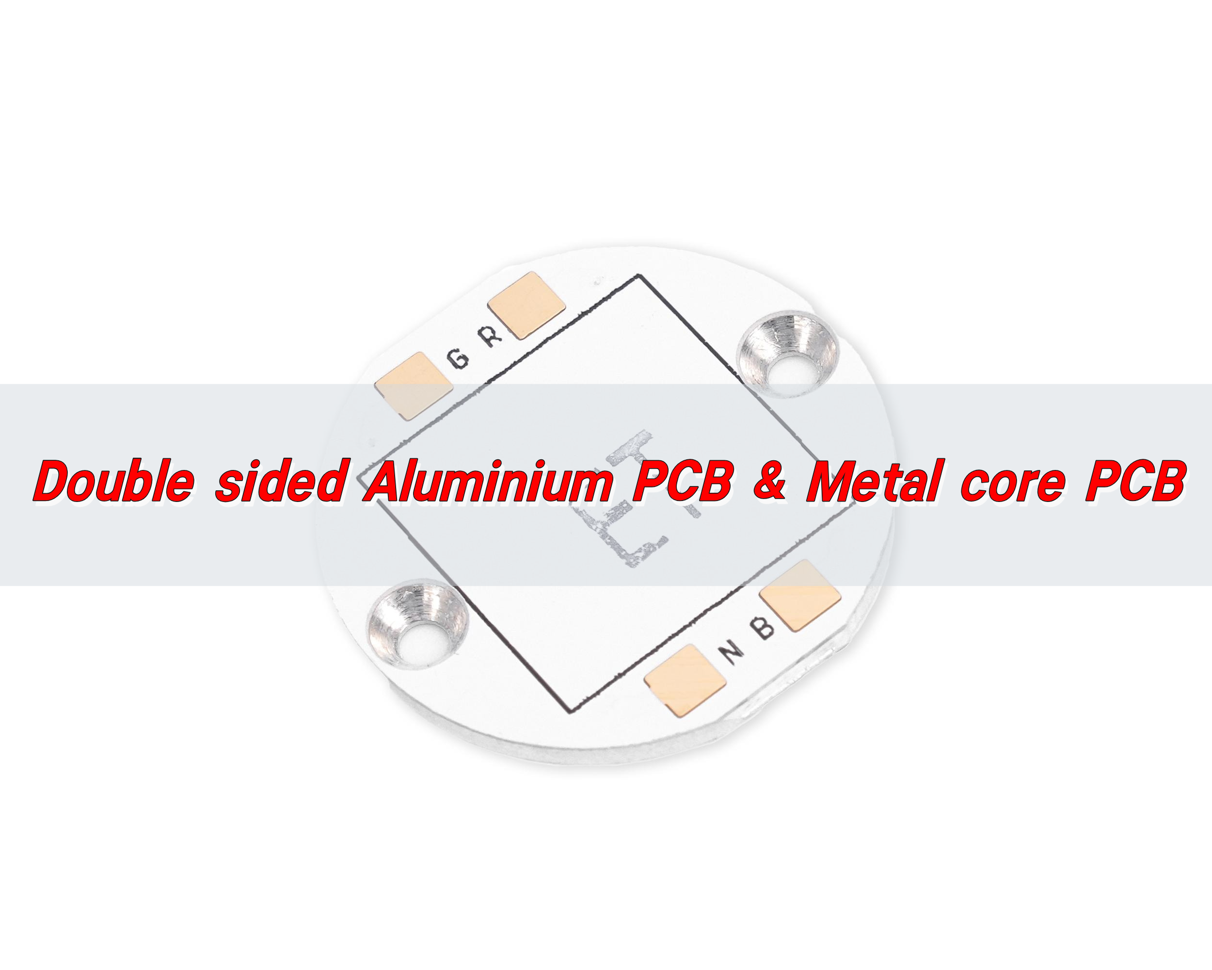
Double sided Aluminium PCB is a metal-based circuit board with two layers of conductive circuits, in which the aluminum substrate is the heat dissipation core, and the two sides are covered with an insulating layer and a copper circuit layer respectively. This structure not only ensures good heat dissipation performance, but also realizes double-sided wiring. It is widely used in electronic products with high power density and high heat dissipation requirements.
What is aluminium backed PCB?
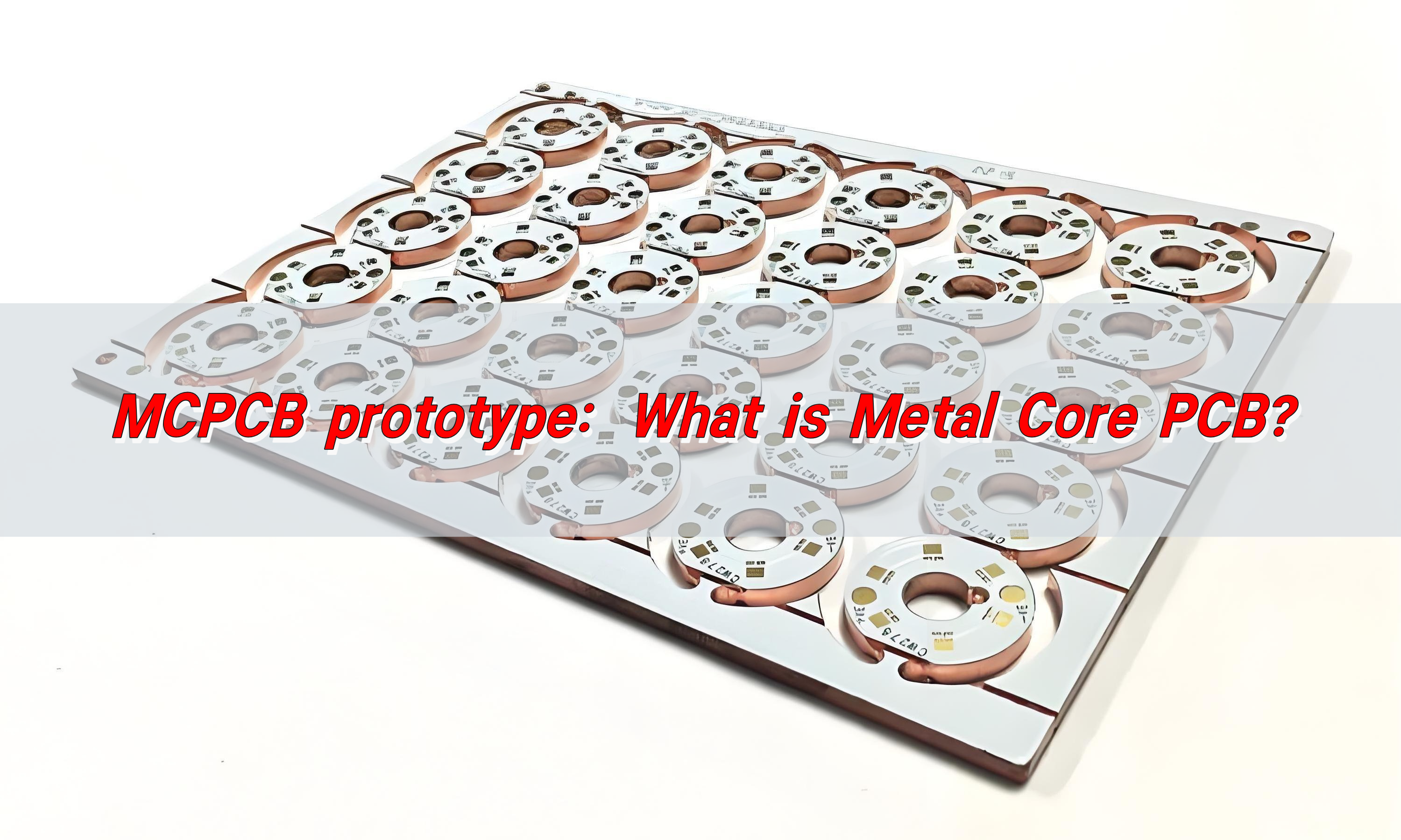
An aluminium-backed PCB, also known as an Aluminium PCB or Metal Core PCB (MCPCB), is a type of printed circuit board where the substrate is made of a metal core, typically aluminum. The core is used to provide better heat dissipation for high-power components, especially in applications that require efficient thermal management.
Aluminium PCBs are widely used in industries like LED lighting, power electronics, and automotive applications, where heat build-up is a significant concern. The metal core helps draw the heat away from the components, preventing overheating and ensuring that the components continue to function optimally.
The aluminum backing also provides the PCB with increased mechanical strength, which is beneficial in more rugged applications.
What are the advantages of double layer aluminium PCB?
Double-sided aluminium PCBs have a unique advantage over single-sided boards. By having two layers of circuitry, double-sided PCBs offer greater design flexibility and more space for components. This is especially important in compact electronic devices where space is at a premium.
The second layer of the PCB allows for more intricate circuit designs and better component placement, ultimately enhancing the performance of the device.
Another significant advantage is the improved heat dissipation. The metal core in double-sided aluminium PCBs works to disperse heat more effectively across both sides of the board, reducing the risk of overheating.
With the two layers of circuitry, the heat can be spread more evenly, ensuring that high-power components are kept within safe temperature limits. This heat dissipation is critical for devices like high-brightness LED lights, power supplies, and other electronics where heat is a constant issue.
Furthermore, double-sided aluminium PCBs are more durable and reliable in demanding environments. The aluminum substrate provides excellent mechanical strength, making the board less susceptible to damage from physical stress or environmental factors such as vibrations. This makes them ideal for automotive and industrial applications, where reliability and durability are essential.
What is aluminum PCB dielectric material?
The dielectric material used in aluminium PCBs is crucial to the board’s performance. The dielectric layer is the insulating material that separates the metal core from the conductive traces on the board.
In the case of aluminium PCBs, the dielectric material typically consists of thermally conductive epoxy resin or other specialized materials that provide electrical insulation while also enhancing heat transfer.
This dielectric material allows for the transfer of heat from the components to the aluminum substrate, preventing the heat from building up at the component level. The dielectric layer is designed to be thin yet durable, offering both electrical insulation and thermal conductivity. This balance between electrical insulation and heat dissipation is key to the efficiency and performance of aluminium PCBs.
How thick is the dielectric layer of aluminum PCB?
The thickness of the dielectric layer in an aluminium PCB depends on the specific design requirements of the application. Generally, the dielectric layer in aluminium PCBs ranges from 30 to 250 microns.
The thickness is chosen based on the need for electrical insulation, thermal conductivity, and the type of components that will be used. For higher-power applications, a thicker dielectric layer may be required to ensure that heat is effectively transferred to the metal core.
On the other hand, for lower-power applications, a thinner dielectric layer may be sufficient.
It’s important to note that the dielectric layer must be carefully chosen to match the thermal and electrical requirements of the PCB. Too thick a layer can reduce the heat dissipation properties, while too thin a layer may not provide sufficient insulation, leading to potential electrical issues. Therefore, the thickness of the dielectric material must be carefully tailored to the needs of the specific design.
What are the cons of aluminum PCB material?
While aluminium PCBs offer a range of benefits, they are not without their drawbacks.
One of the primary challenges with aluminium PCBs is their higher cost compared to traditional FR4 (fiberglass) PCBs. The material itself is more expensive, and the manufacturing process is more intricate, leading to higher production costs. This can make aluminium PCBs less suitable for low-cost, high-volume applications where budget is a primary concern.
Another disadvantage of aluminium PCBs is their relatively brittle nature. While the metal core provides mechanical strength, the overall structure can be more prone to cracking or damage compared to standard FR4 PCBs. This can be an issue in environments with high mechanical stress or extreme conditions.
Additionally, the assembly process for aluminium PCBs can be more complicated, as the metal core requires specialized equipment for soldering and mounting components.
Lastly, the design complexity can increase when working with aluminium PCBs, especially when designing for double-sided or multi-layer PCBs. The process of placing components on both sides of the PCB and ensuring proper heat dissipation requires more planning and precision. This can make aluminium PCBs less versatile for designs that don’t have significant thermal management needs.
What temp can aluminum PCB withstand?
Aluminium PCBs are known for their excellent thermal management properties. The metal core helps dissipate heat effectively, ensuring that the components on the board are kept within safe operating temperatures.
Generally, aluminium PCBs can withstand temperatures ranging from -40°C to 150°C, though this can vary depending on the specific material and design used.
For high-power applications, where significant heat is generated, it’s essential to ensure that the PCB design includes adequate heat dissipation methods, such as larger copper pads or heat sinks.
The thermal conductivity of the aluminium core helps to transfer heat away from the components, but in extreme cases, additional cooling methods may be necessary to prevent overheating.
The heat tolerance of aluminium PCBs makes them ideal for use in LED lighting, automotive electronics, power supplies, and other devices that generate significant heat.
By effectively managing the heat, aluminium PCBs ensure that the components remain within safe operating temperatures, thus prolonging the lifespan of the device and improving overall performance.
What is the difference between copper and aluminum PCB?
The main difference between copper and aluminium PCBs lies in the material used for the substrate. Copper PCBs, also known as copper clad PCBs, use copper as the base material, while aluminium PCBs use an aluminium metal core. Both types of PCBs offer good thermal management, but aluminium PCBs have a clear advantage in heat dissipation.
Aluminium PCBs are better at dissipating heat compared to copper PCBs because of the high thermal conductivity of aluminium. This makes them ideal for applications that require efficient heat management, such as high-power LEDs or power electronic components.

On the other hand, copper PCBs are often preferred in applications where electrical conductivity is the priority, such as high-frequency or high-speed circuits. Copper has a lower resistance than aluminium, which can result in better electrical performance in certain applications.
In terms of cost, aluminium PCBs tend to be less expensive than copper PCBs, making them a more cost-effective option for thermal management in most applications.
However, copper PCBs can still be preferred for designs where electrical performance is more critical than heat dissipation.
Conclusion:
Double-sided aluminium PCBs offer unique advantages for applications requiring excellent thermal management and high mechanical strength. While they come with some challenges, including higher costs and design complexities, they are well-suited for industries like LED lighting, automotive electronics, and power supplies.
If you are looking for a professional PCB manufacturer to bring your designs to life, contact us at sales@bestpcbs.com. We offer expert design, manufacturing, and assembly services to meet your specific needs.