pcb
Home > Blog

Archive for 8 月, 2023

What You Know About Counterbores in PCB Design and Manufacturing
星期五, 18 8 月, 2023

In the world of design and manufacturing, precision is paramount. Every detail, down to the placement of a single component, can impact the performance and appearance of a product. This is where the concept of counterbores comes into play, a technique employed in various industries to create recessed areas for components or fasteners.

But firstly, what is counterbore?  Today we will show you the definition and applications of the countersink in a PCB design. 

Definition and Applications:

A counterbore is a cylindrical, flat-bottomed hole that is strategically cut into a material to accommodate specific components or fasteners. It is commonly used in various industries, including woodworking, metalworking, and mechanical engineering. The purpose of a counterbore is to create a recessed area where a component, such as a bolt head, nut, or other hardware, can sit flush with or below the surface of the material. This technique ensures a smooth appearance, prevents interference with other components, and provides mechanical stability.

Counterbores in PCB Design and Manufacturing

In the realm of printed circuit boards (PCBs), counterbores play a crucial role in achieving efficient and functional designs. PCBs are essential components in electronic devices, and their design requires careful consideration of component placement, connectivity, and mechanical stability. Counterbores in PCBs serve several important functions:

  1. Component Alignment and Clearance:  Certain components on a PCB, such as connectors, switches, or specialized modules, require precise alignment and clearance for optimal functionality. A counterbore can be introduced to create a recessed area that accommodates these components, ensuring proper alignment with neighboring components and minimizing the risk of interference.
  • Flush Mounting: To maintain a sleek and compact design, some components need to be mounted flush with the surface of the PCB. A counterbore creates a flat-bottomed recess that allows the component to sit at the same level as the PCB surface, contributing to an aesthetically pleasing and functional layout.
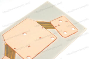
(Counterbore_hole_in_heavy_copper_PCB)
  • Mechanical Support: Components that are susceptible to mechanical stress or impact may benefit from additional support. By incorporating a counterbore, the PCB design can provide a more secure location for these components, reducing the risk of damage.
  • Heat Dissipation Enhancement: In applications where certain components generate significant heat, such as power amplifiers or processors, heat sinks are often employed to dissipate the heat. A counterbore can facilitate proper alignment and contact between the heat sink and the component, optimizing heat transfer and overall thermal performance.
(Detail_counterbore_hole)

The production of counterbores in PCBs involves specialized manufacturing techniques. BEST Technology as a professional PCB manufacturer, we will use precision drilling and routing equipment to create accurately sized and positioned counterbores.

If you want to know more about the counterbores, welcome to follow our post or contact us.

You may also like

Enhancing UV LED Performance with MCPCB: Advantages and Innovative Applications
星期四, 10 8 月, 2023

In the field of ultraviolet light-emitting diodes (UV LED), the integration of Metal Core Printed Circuit Boards (MCPCB) plays a significant role in improving UV LED performance, thermal management, and overall reliability. In this blog post, we will explore the importance of MCPCB in UV LED applications, highlighting its advantages with concrete data to demonstrate its practicality.

  1. Efficient Heat Dissipation:

MCPCBs excel in efficient heat dissipation, ensuring optimal UV LED performance and longevity. With a metal core typically made of aluminum or copper, MCPCBs possess high thermal conductivity. For instance, MCPCBs have a thermal conductivity coefficient of normally 1.0-3.0 W/mK, it needs to be customized if the thermal conductivity exceeds 3.0W/mk. this exceptional thermal conductivity allows for rapid dissipation of generated heat, preventing heat accumulation and ensuring UV LEDs operate within their optimal temperature range.

2. Enhanced Thermal Conductivity:

MCPCBs contribute to effective heat dissipation through improved thermal conductivity. Studies indicate that MCPCBs can enhance thermal conductivity up to ten times higher than standard FR4 PCBs. Because the stack up of MCPCB is different with PCB, please see below stack up. This enhanced thermal conductivity aids in achieving a uniform temperature distribution across the entire MCPCB, reducing the risks of hotspots and thermal stress on UV LEDs. Consequently, UV LEDs can maintain their performance and reliability even during extended operation.

(MCPCB_stack_up)
1ozCopper layer
1.5mm without copperCore base
(FR4PCB_stack_up)

3. Reliability in Harsh Environments:

MCPCBs are designed to withstand harsh environments, ensuring reliability in UV LED applications. The metal core of MCPCBs provides higher mechanical strength and resistance to thermal stress. For example, the coefficient of thermal expansion (CTE) of an MCPCB can be matched with UV LEDs, minimizing the risk of mechanical failures caused by thermal mismatch. These features enable MCPCBs to operate reliably even in high-temperature environments or under exposure to ultraviolet radiation, thereby extending the lifespan of UV LED devices.

4. Electrical Isolation:

MCPCBs offer electrical isolation between the metal core and circuit layers, ensuring safe and reliable operation of UV LEDs. The dielectric layer, typically made of materials such as epoxy resin or thermally conductive dielectric (TCF), exhibits high breakdown voltage and insulation resistance. This electrical isolation minimizes the risk of short circuits or electrical interference, protecting UV LEDs and the entire system from potential damage.

5. Performance Optimization:

By incorporating MCPCBs into UV LED technology, manufacturers can optimize the performance of their UV LED devices. The improved heat dissipation and thermal conductivity of MCPCBs enable UV LEDs to operate at maximum efficiency. Research shows that using MCPCBs can reduce LED junction temperatures by up to 20-30°C, improving light output and enhancing overall performance. This optimal performance ensures consistent UV light generation, making MCPCBs an ideal choice for various UV LED applications, including curing, sterilization, and phototherapy.

Conclusion:

The use of MCPCBs in UV LED technology offers practical benefits in heat dissipation, thermal conductivity, reliability, and electrical isolation. Concrete data and research support the effectiveness of MCPCBs in efficient heat management, even in harsh environments, enabling reliable operation of UV LEDs. With enhanced performance provided by MCPCBs, UV LED systems can deliver consistent, efficient, and durable UV light output, expanding the possibilities of UV applications in various industries. The utilization of MCPCBs further solidifies their critical role as a key supporting technology in the UV LED field.

If you are designing a metal core PCB and seeking for a reliable manufacturer, welcome to leave you message or contact us directly.

You may also like

Do You Know What Is HDI Board?
星期四, 10 8 月, 2023

HDI boards are a type of printed circuit board (PCB) technology that enables higher circuit density and smaller form factors compared to traditional PCBs. HDI boards are commonly used in applications where space is limited, such as mobile devices, wearables, and aerospace systems.

Best Technology has rich experience in HDI rigid flex pcb manufacturing, below is one of our 7 layers HDI rigid flex pcb.

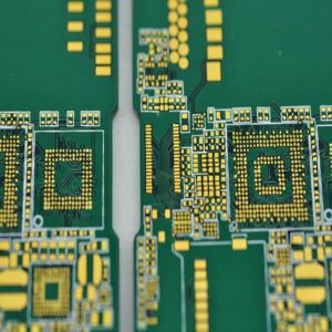
In Best Technology, our HDI board usually has the blind holes or buried holes, and the minimum hole size usually is 0.1mm. This board has the blind and buried holes, and the minimum hole size is 0.1mm. 100 ohm differential impedance control with 50 single ended impedance control. It’s surface finish is ENIG, 1oz copper for outer layers, 1/2oz copper for inner layers, green solder mask with white silkscreen. total thickness is 1.4mm.

Here are some key features and aspects of HDI boards:

  1. High Density: HDI boards are designed to accommodate a large number of densely packed components and interconnections. They typically have multiple layers with high routing density, allowing for more complex circuitry in a smaller footprint.
  • Microvias: HDI boards extensively use microvias, which are very small holes drilled into the board to create electrical connections between different layers. Microvias are smaller in size compared to traditional vias, allowing for increased routing density.
  • Staggered and Stacked Microvias: HDI boards employ different types of microvias, including staggered and stacked microvias. Staggered microvias connect adjacent layers, while stacked microvias connect non-adjacent layers, providing even higher routing density.

Blind and Buried Vias: HDI boards often utilize blind and buried vias, which are vias that do not extend through the entire board. Blind vias connect an outer layer with one or more inner layers, while buried vias connect inner layers only. These vias help optimize space and increase routing capabilities.

  • Fine Pitch Components: HDI boards support the use of fine pitch components, such as microcontrollers, ball grid array (BGA) packages, and small surface-mount devices (SMDs). The high routing density and smaller features of HDI boards make them suitable for accommodating these tiny components.
  • Increased Signal Integrity: HDI boards can provide improved signal integrity due to shorter trace lengths and reduced noise interference. The compact design minimizes signal loss and impedance mismatches, allowing for better performance in high-frequency applications.
  • Design Considerations: Designing HDI boards requires expertise in factors such as layer stacking, via types, trace widths, and clearances. Advanced design software and manufacturing techniques are often employed to ensure precise alignment and reliability of the intricate interconnections.
  • Manufacturing Challenges: HDI boards can be more challenging to manufacture compared to standard PCBs. The use of smaller features and complex layer structures requires specialized fabrication techniques, such as laser drilling, sequential lamination, and precise registration control.

HDI technology has become increasingly prevalent in the electronics industry, enabling the development of smaller, lighter, and more sophisticated devices. It offers enhanced electrical performance, improved reliability, and greater design flexibility. If you have any comments about the HDI board, please feel free to contact Best Technology Team e-mail: sales@bestfpc.com.

You may also like