pcb
Home > Blog

Posts Tagged ‘circuit’

What are inverters and converters? What do they do?
星期一, 9 9 月, 2024

Electricity is ubiquitous in our lives, and the use of all devices is closely related to electricity. The use of electricity depends on how to control and convert it. Among them, the indispensable tools are inverters and converters, which can convert electrical energy into different forms to meet various needs.

What are AC and DC?

1. Definition of alternating current and direct current:

  • Alternating current (AC) refers to the current whose direction changes periodically over time, and the average current in one cycle is zero.
  • The waveform of alternating current is usually a sine curve, but there can also be other waveforms, such as triangular waves and square waves. Alternating current is widely used in power transmission and industrial applications.
Inverters and converters? What effect do they have on current flow?
  • Direct current (DC) refers to the current whose direction is constant.
  • The magnitude and direction of direct current do not change with time. Common DC power sources include dry batteries and storage batteries. The direction of pulsating direct current does not change, but the magnitude changes with time. It usually needs to be filtered to become smooth direct current.

2. The difference between AC and DC:

  • The main difference between AC and DC is whether the direction of the current changes over time.
  • The direction of AC changes periodically, while the direction of DC remains unchanged. In addition, the average value of AC in a cycle is zero, while the current and voltage of DC remain constant.

3. Application scenarios of AC and DC:

  • AC is mainly used for power transmission and industrial applications because its waveform is a sinusoidal curve, which is suitable for long-distance transmission. DC is often used in situations where constant current is required, such as battery-powered electronic devices.
Inverters and converters? What effect do they have on current flow?

How do you convert from DC to AC?

DC can be converted into AC through an inverter. The inverter usually consists of an inverter bridge, control logic, and filter circuits.

Inversion is a current conversion process opposite to rectification, which converts DC into AC. When the inverter side, i.e., the AC side, is connected to the power grid, it is called active inversion, and when the inverter side, i.e., the AC side, is directly connected to the load, it is called passive inversion.

The inverter circuit can convert DC power into AC power of any frequency and voltage under the control of the control circuit, so it is widely used, for example, when DC power is needed to supply power to AC loads.

What is dc to ac inverter?

‌Inverter is a device that converts DC power into AC power. ‌‌

Inverters and converters? What effect do they have on current flow?

The inverter is mainly composed of an inverter bridge, control logic and filter circuit, which can convert DC power (such as batteries, storage batteries) into fixed frequency and voltage or frequency and voltage AC power, usually 220V, 50Hz sine wave.

Inverters are particularly widely used in automobiles. They can drive various electrical appliances and tools by connecting to batteries, making it possible to use household appliances when driving or traveling.

Inverters can be divided into sine wave inverters and square wave inverters according to the output waveform. Although the sine wave inverter is more expensive, it can be applied to various loads, and the output waveform is closer to the mains, which is friendly to electrical equipment.

The efficiency of the inverter is an important indicator of its performance, which indicates the ratio of output power to input power. With the development of technology, inverters are showing a trend of high frequency, high performance and miniaturization, and are widely used in various fields of power electronics technology.

What is dc to ac converter?

An AC to DC converter is a device whose main function is to convert alternating current (AC) into direct current (DC). Such converters are commonly used in household appliances, computers, mobile phone chargers and other devices to convert the AC power provided by the power grid into the DC power required by the device.

The working principle of the AC/DC converter involves converting the AC power into smooth DC power through a rectification and filtering process. This converter can be bidirectional in terms of power flow, that is, power can flow from the power source to the load (called rectification) or from the load back to the power source (called active inversion).

The working principle of the AC/DC converter involves several key steps:

  • ‌Rectification‌: Converting AC power into unidirectional pulsating DC power is achieved by using a rectifier, which can be a half-wave rectifier or a full-wave rectifier, depending on the specific technology used.
  • ‌Filtering‌: Filtering is performed by using capacitors to eliminate the pulsating components generated during the rectification process to obtain a smoother DC power.
  • ‌Voltage stabilization‌: In some applications, voltage stabilization may also be required to ensure the stability of the output voltage.

The design and application of AC/DC converters are limited by many factors, including safety standards, electromagnetic compatibility (EMC) requirements, and power system optimization design.

In addition, the use of high-voltage, high-current switches increases the power consumption, which to a certain extent limits the modularization process of AC/DC converters.

What is the difference between an inverter and converter?

The main difference between an inverter and a converter is that they have different functions and conversion directions. ‌

Although inverters and converters sound similar, their functions and conversion directions are completely different. The main function of an inverter is to convert direct current (DC) into alternating current (AC), while a converter does the opposite, converting AC into DC. This difference makes them play their respective roles in different application scenarios.

1. ‌Inverter‌:

  • The main application of an inverter includes converting electricity generated by a DC power source (such as a battery) into AC to meet the needs of AC equipment. The advantages of the inverter include high conversion efficiency, fast startup, good safety performance, etc., but it may also generate noise due to its working principle, and corresponding countermeasures need to be taken to reduce the noise.

2. Converter:

  • Unlike the inverter, the main function of the converter is to convert AC to DC.
  • This is usually achieved through the process of half-wave rectification and full-wave rectification, which involves passing the positive half-cycle or positive and negative cycles of AC through the rectifier circuit, and then further processing through capacitor filtering and voltage stabilization circuit to finally obtain DC.
  • Converters are widely used in various electronic devices that need to convert AC power to DC power.

In general, although inverters and converters are similar in name, their functions and conversion directions are completely different. Inverters convert DC to AC and are suitable for using DC power for AC devices; while converters convert AC to DC to meet the needs of devices that require DC power.

Why would you use an inverter?

The main reason for using an inverter is to convert DC to AC to meet the power needs of various devices and systems. ‌

The main function of the inverter is to convert direct current (DC) into alternating current (AC), which is necessary in many fields and scenarios. Here are some of the main uses of the inverter:

  • 1. Household electricity: The inverter can convert the DC power of the car battery or other DC power source into the AC power required by household appliances, so that the car or other DC power source can power household devices.
  • 2. Emergency power supply: In the event of a power outage or power outage, the inverter can convert the DC power of the backup power source (such as gasoline generators, solar panels, etc.) into AC power to provide power support for key equipment.
  • 3. Electronic devices: Many portable electronic devices (such as laptops, mobile phones, cameras, etc.) use DC batteries as power sources. The inverter can convert DC power into AC power to provide power for these devices.
  • 4. Industrial applications: In industrial production, the inverter can convert high-voltage DC power into low-voltage AC power to meet the power needs of different equipment and systems.
  • 5. Electric vehicle charging: With the popularity of electric vehicles, inverters are increasingly used in electric vehicle charging stations, which convert direct current from the power grid into alternating current required by electric vehicle batteries.
  • 6. Radio communication: In radio communication, inverters are used to convert direct current into radio frequency power to transmit and receive radio signals.

Therefore, inverters play an indispensable role in modern society and are widely used in various fields to provide necessary power conversion and support for various devices and systems.

What are the disadvantages of an inverter?

1. Harm to batteries: Inverters increase the burden on batteries and shorten the life of batteries. Inverters generate electromagnetic interference and heat when working, which may interfere with batteries, causing unstable battery voltage or internal damage to batteries.

2. Energy loss: The conversion efficiency of inverters is relatively low, and there will be a certain amount of energy loss.

3. High cost: The cost of inverters is high, which may not be suitable for some low-cost applications.

4. May generate electromagnetic interference and heat: The inverter will generate high-frequency electromagnetic waves and a certain amount of heat when working, which may affect the working performance of other electronic equipment and may even cause safety problems.

In summary, although the inverter provides convenience in many applications, its disadvantages cannot be ignored, including energy loss, high cost, possible electromagnetic interference and heat, and potential safety hazards.

Conclusion:

Inverters and converters are indispensable in modern electrical systems to ensure that energy flows to where it is needed in the right form. Whether it is converting DC to AC for renewable energy systems, using batteries to power equipment, or ensuring uninterruptible power supply, these tools can achieve a smooth transition between different types of current.

You may also like

How to understand circuit diagrams?
星期二, 27 8 月, 2024

A circuit diagrams, also known as an electrical diagram, schematic diagram, or electronic schematic diagram, is a graphical representation of a simplified circuit. It is a visual tool for the design, construction, and maintenance of electrical and electronic equipment.

By utilizing images or standard symbols of different components, circuit diagrams can simplify the description of the components of a circuit and their interconnections. This enables electricians and technicians to easily understand the relative positions of components and their relationships in the circuit.

How to learn circuit diagram easily?

How to understand circuit diagrams

1. ‌Knowing electrical components‌: First, you need to understand common electrical components, such as AC contactors, push button switches, thermal relays, time relays, etc., and master their working principles and structures.

2. ‌Memorizing electrical symbols‌: Learn and memorize common electrical letters and graphic symbols, such as AC contactors (KM), intermediate relays (KA), etc.

3. ‌Basic theory learning‌: Have basic electrical basic knowledge, such as the relationship between the rotation direction of a three-phase asynchronous motor and the phase sequence of the power supply‌.

4. ‌Practical operation‌: If conditions permit, disassemble electrical components to familiarize yourself with their internal structure, or understand the internal structure and working principle through physical diagrams.

5. Practice step by step: Start with simple circuit diagrams and gradually try to analyze more complex circuit diagrams. Through continuous practice, you can gradually improve your ability to interpret circuit diagrams.

6. Use the principle of circuit simplification: Learn and apply the basic principles of circuit simplification, such as ignoring wire resistance, switch processing, etc.

7. Combine theory with practice: Apply theoretical knowledge to practice, for example, try to design your own circuit based on the learned electrical schematics, or design circuit diagrams according to actual needs.

Through the above steps and methods, you can learn and understand circuit diagrams more easily.

What are the 4 rules for drawing circuit diagrams?

The 4 rules for drawing circuit diagrams are:

1. Circuits or components should be arranged according to function and arranged in working order as much as possible. ‌

2. All electrical components should be represented by graphic symbols and text symbols that are unified by national standards. ‌

3. Different parts of the same electrical component (such as coils and their multiple contacts) are often not drawn together, but should be marked with the same text symbol.

4. In the circuit schematic, all contacts of the control appliance should be drawn in the “non-excitation” state.

These rules together ensure that the circuit diagram is clear, accurate and easy to understand, and provide an important reference for the design and maintenance of electronic equipment and systems.

How to get better at reading schematics?

Understand the basic composition and logic block diagram of the circuit: First, you need to understand the relationship between the various components in the schematic, such as power supply, reset, etc., and the connection relationship between the various devices on the motherboard.

Pay attention to details: When reading the schematic, you need to pay attention to details, such as the model of the components, the connection method, etc.

Do more exercises: Through a lot of reading and practice, you can become familiar with various circuit types and topics and gain more knowledge and experience from them.

Use relevant knowledge of analog circuits and circuit design: Having a deep understanding of the basic concepts and principles of analog circuits and circuit design can help better understand how the various parts in the schematic work together.

What are the components of common circuit schematics?

Power supply: The power supply provides electrical energy to the circuit in the form of voltage and current. Every functional electronic circuit requires a DC or AC power supply.
How to understand circuit diagrams

Switches: Switches can make or break connections in a circuit. They can also change the path that current flows.

How to understand circuit diagrams

Capacitors: Capacitors are passive electronic components that store electrical charge. There are two common types of capacitors: nonpolar capacitors and polar capacitors.

Diodes: A diode is a polarized device that allows current to flow in only one direction. Because it is polarized, it has a positive terminal (anode) and a negative terminal (cathode). The flat side of the triangle is the anode, and the line is the cathode.

Potentiometers and variable resistors: Both variable resistors and potentiometers have an arrow added to the standard resistor symbol. Variable resistors are still two-terminal devices, so the arrow just goes diagonally through the middle. Potentiometers are three-terminal devices, so the arrow becomes the third terminal (the wiper).

How to understand circuit diagrams?

Resistors: The most basic circuit component and symbol, resistors on schematics are usually represented by a few jagged lines with two terminals extending outward. Schematics using international symbols may use a featureless rectangle instead of a wavy line.

How to understand circuit diagrams

What does a resistor do in a circuit?

Resistance (usually represented by “R”) is a physical quantity that indicates the magnitude of the resistance of a conductor to the current in physics.

The greater the resistance of a conductor, the greater the resistance of the conductor to the current. Different conductors generally have different resistances, which is a characteristic of the conductor itself. Moreover, the main functions of resistors in circuits include current shunting, current limiting, voltage division, biasing, filtering (used in combination with capacitors), impedance matching, and converting electrical energy into internal energy.
What is the simplest of all circuit diagrams?

The simplest of all circuit diagrams is the series circuit. ‌

How to understand circuit diagrams

The series circuit is one of the most basic circuit connection methods, consisting of components such as power supply, wires, switches, and electrical appliances. The characteristic of this circuit is that the path of current passing through each component is single, that is, the current flows out from the positive pole of the power supply, passes through each component and reaches the negative pole of the power supply.

The structure of the series circuit is simple and easy to understand and construct. Therefore, the series circuit is an important concept in the basic stage of circuit learning. In addition, the single path nature of the series circuit makes it the basis for understanding and analyzing complex circuits, laying the foundation for subsequent learning of more complex circuit structures such as parallel circuits and hybrid circuits.

Conclusion:

Circuit diagrams are an important tool in the field of electronics that provide a visual representation of circuits. These diagrams are essential for designing, troubleshooting, and understanding how electronic components are interconnected.

Whether you are a beginner or an experienced engineer, mastering the skill of reading circuit diagrams is the foundation for a successful career in electronics. It enables you to effectively design, troubleshoot, and understand electronic circuits. You can master this important skill by becoming familiar with common symbols, understanding circuit layouts, and practicing regularly.

You may also like

Do you know the relationship between copper thickness and circuit width & spacing?
星期六, 2 9 月, 2023

We know the precision control and performance of a product are paramount, only know that PCB can be built with a nice function, so, to understand the intricate relationship between copper thickness and circuit width and spacing is pivotal. These two parameters are like the gears of a well-oiled machine, interlocking in ways that significantly influence the printed circuit board‘s functionality, signal integrity, and manufacturability. If the designer does not consider the relationship between these two, the design may need to be modified in subsequent production.

In order to avoiding this information, let’s embark on a deeper exploration of this dynamic relationship to uncover its nuances and implications now,

Frist of all, we need to know some basic information about PCB, like copper thickness, circuit width and spacing.

  1. The Essence of Copper Thickness

Copper, known for its exceptional electrical conductivity, is the lifeblood of any PCB. The copper thickness refers to the amount of copper deposited onto the board’s surface during fabrication. It’s the foundation upon which the traces, the intricate pathways that carry electrical signals, are built. The standard copper thickness is often measured in ounces per square foot (oz/ft²) or micrometers (µm). Common options include 1oz (35µm), 2oz (70µm), and even higher, it depends on customer’s requirement.

  • Circuit Width and Spacing

Circuit width and spacing, though often overlooked, are integral components that determine a PCB’s performance, integrity, and overall functionality. Circuit width refers to the dimension of the conductive traces, while spacing pertains to the distance between these traces. These seemingly simple dimensions have a profound impact on the PCB’s behavior.

Secondly, Unveiling the Intricate Relationship

The relationship between copper thickness, circuit width, and spacing is a sophisticated interplay of electrical properties, heat dissipation, and signal integrity. Let’s delve deeper into this complex web of interactions:

Current-Carrying Capacity and Copper Thickness: Copper thickness directly influences a trace’s ability to carry current without succumbing to overheating. Thicker copper translates to higher current-carrying capacity and reduced resistive losses. However, the trade-off is that wider traces are necessary to accommodate the increased copper thickness.

Resistance and Circuit Width: Wider traces exhibit lower resistance, which in turn reduces voltage drop and enhances the efficiency of signal transmission. Designers must strike a balance between trace width, copper thickness, and available board space.

Spacing and Unwanted Interactions: As circuit spacing decreases, the probability of unwanted interactions, such as crosstalk and electromagnetic interference, rises. Thicker copper can exacerbate these issues due to its larger cross-sectional area. Maintaining appropriate spacing between traces is pivotal to prevent signal degradation and maintain integrity.

Heat Dissipation and Trace Width: Thicker copper also aids in better heat dissipation, a crucial consideration for power-intensive applications. However, this can necessitate wider traces to manage the thermal load effectively.

Signal Integrity and Crosstalk: Smaller spacing reduces the risk of crosstalk, but it’s a double-edged sword. Thicker copper traces may introduce higher capacitance, altering impedance and potentially impacting signal integrity. This delicate balance requires careful consideration during design.

For now, we have known the relationship between them, how to develop a best design between the circuit width & spacing and copper thickness, which depends on what’s you really want, the huge current or heat management? Following details should be considered if you want to develop the best circuit width & spacing.

Current Requirements: Start by understanding the current requirements of your traces based on the components and operational conditions. Selecting the appropriate copper thickness and trace width ensures the PCB can handle the anticipated loads.

Thermal Management: Thicker copper facilitates heat dissipation, which is advantageous for power-dissipating components. However, remember that it might necessitate wider traces to ensure effective heat transfer.

Manufacturability: While thicker copper can enhance current-carrying capacity and heat dissipation, it might pose manufacturing challenges. Consult with PCB manufacturers to align your design choices with their capabilities.

Signal Integrity Analysis: Utilize simulation tools to analyze signal integrity, especially when dealing with smaller spacing and thicker copper. These tools provide insights into impedance matching, potential crosstalk, and overall performance.

Flexibility VS Rigidity: While thicker copper enhances many aspects, it can impact the PCB’s flexibility, crucial for certain applications. Evaluate the mechanical demands of your project and strike the right balance.

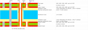
Regarding metal core PCB in Best Technology, the copper thickness and its accordingly circuit width & spacing like below, furthermore, it would be better if you can let me know your copper thickness before checking your drawing, we will give you the best solution before formal production.

Copper thicknessMinimum circuit widthMinimum circuit spacing
0.5-2oz0.25mm0.23mm
3oz0.35mm0.3mm
4oz0.4mm0.38mm
(trace_design_guide_of_MCPCB)

Conclusion: Striking the Optimal Balance

The intricate relationship between copper thickness, circuit width, and spacing in PCB design embodies a delicate equilibrium that significantly influences a design’s performance and functionality. This nuanced interplay directly impacts parameters such as current-carrying capacity, resistance, heat dissipation, and signal integrity.

Achieving the optimal balance between these factors requires a deep understanding of electrical properties, thermal considerations, and signal behavior. Designers must carefully evaluate the specific requirements of their projects and leverage simulation tools to fine-tune their choices. Collaboration with PCB manufacturers ensures alignment with manufacturing capabilities.

The dynamic nature of this relationship underscores the constant evolution of PCB technology. As devices become smaller, faster, and more interconnected, the demand for intricate layouts intensifies. Designers must continuously adapt to new challenges, pushing the boundaries of what’s achievable while adhering to the fundamental principles that govern PCB design.

You may also like