Copper thickness is a key factor that affects how your board performs. Choosing the right copper thickness is an important part of PCB design, it affects how well your circuit works, how long it lasts, and even how much it costs. In this blog, weâll break down why copper thickness matters, how to pick the right option for your PCB designââ to help you make informed decisions for your next project.
Why Copper Thickness Matters?
1. Current Carrying Capacity
Thicker copper layers handle higher currents without overheating. For example:
1 oz copper: Supports up to ~3A per 10mm trace width.
2 oz copper: Doubles the capacity to ~6A for the same width.
 Critical for power circuits like motor controllers or LED drivers.
3 oz+ Copper (140”m+):
Handles 12A+ per 10mm, suited for extreme applications like inverters or industrial power supplies. However, thicker copper increases fabrication costs and requires specialized manufacturing.
2. Signal Integrity
High-frequency designs (e.g., RF, 5G): Thinner copper (0.5 ozâ1 oz) with smooth surfaces reduces signal loss.
Standard circuits: 1 oz copper is sufficient for most low-frequency applications.
3. Durability
Thicker copper (â„2 oz) withstands thermal stress during soldering and mechanical wear in harsh environments.
Thin copper (0.5 oz) may crack under repeated vibration or temperature changes.
4. Cost Efficiency
Thicker copper increases material costs and requires longer etching times.
Based on our 19+years experiences in the PCB manufacturing field, today I would like to share you 6 Strategies How to Choose the Right Thickness
1. Calculate Current Requirements
Use the IPC-2152 standard or online tools (e.g., Saturn PCB Toolkit) to determine the minimum trace width and copper weight for your current.
Example: A 5A power trace with 1 oz copper needs a 2mm width. With 2 oz copper, the width drops to 1mm, saving space.
2. Prioritize Space vs. Performance
High-density designs: Use thinner copper (0.5 ozâ1 oz) to fit more traces.
Power-heavy boards: Option for 2 ozâ6 oz copper to reduce trace widths and avoid overheating.
3. Factor in Manufacturing Limits
Thin copper (0.5 oz): Prone to over-etching; requires tighter process control.
Thick copper (>3 oz): Needs specialized plating and etching, increasing lead time and cost.
Common Mistakes to Avoid
Ignoring Current Density: Thin traces with high current cause burnout.
Over-Designing: Using 3 oz copper for low-power signals wastes space and money.
Neglecting Manufacturer Feedback: Always confirm your fab houseâs capabilities (e.g., max/min copper weight).
Conclusion
Choosing the right copper thickness balances performance, cost, and manufacturability. By aligning your designâs needs with industry standards and manufacturer capabilities, you can avoid costly redesigns and ensure long-term reliability.
Also, if you have more questions about PCB copper thickness or need help with your design, feel free to reach out to a send an inquiry. weâll help you optimize copper thickness and maximize your boardâs potential.
Need fast PCB prototyping solutions? Fast PCB Prototyping enables quick hardware testing through rapid manufacturing, requiring careful vendor choice, thermal optimization, signal testing, and quality checks to ensure 24-hour delivery with reliable performance.
Best Technology stands out as a premier fast PCB prototype manufacturer by delivering industry-leading 24-hour turnaround times without compromising quality. Our automated smart factories equipped with advanced 6-layer simultaneous drilling technology and high-speed automated SMT production lines enable rapid prototyping cycles that are 40% faster than industry standards. We maintain this speed while achieving 99.8% first-pass yield through precision SMT placement systems and real-time thermal monitoring. For mission-critical projects, our express service guarantees functional prototypes within 24 hours, supported by 24/7 engineering support and live production tracking. Clients benefit from our decade of expertise in high-speed digital and RF designs, with specialized solutions for HDI, flex-rigid, and high-frequency boards up to 77GHz. Our ISO 9001-certified quality system combines automated optical inspection (AOI), flying probe testing, and signal integrity verification to ensure reliability at accelerated production speeds. The integration of cutting-edge SMT assembly infrastructure, optimized logistics networks, and dedicated quick-turn production lines makes us the preferred partner for startups requiring rapid iteration capabilities. Welcome to contact us: sales@bestpcbs.com.
What Is Fast PCB Prototyping?
Fast PCB Prototyping is the process of rapidly manufacturing functional printed circuit board samples for testing and validation before mass production. It enables hardware developers to quickly verify designs, identify potential issues, and accelerate product development cycles. Leading Fast PCB Prototype Manufacturers specialize in delivering high-quality prototypes within 24-72 hours using advanced manufacturing techniques and strict quality control. This service is particularly valuable for international trade clients who need to maintain competitive timelines while ensuring reliability. By partnering with trusted fast PCB prototyping providers, businesses can reduce development costs, speed up market entry, and minimize risks in electronics manufacturing.
What Are Benefits of Fast PCB Prototyping?
Benefits of fast PCB prototyping:
Speed to Marketâ â Fast PCB Prototyping cuts waiting time from weeks to 1-3 days, helping global clients meet tight deadlines and stay ahead of competitors.
Cost Savingsâ â Early design validation through fast PCB prototyping prevents expensive rework in mass production, reducing overall project costs.
Risk Reductionâ â Leading fast PCB prototype manufacturers test functionality before full-scale production, minimizing defects and supply chain delays.
On-Call Team: Rotate shifts to handle design queries, DFM reviews, and test failures.
Live Chat: Use tools like Slack or Microsoft Teams for instant communication.
10. Pre-Certification Preparation
Documentation: Pre-fill FCC/CE test reports using simulated data to expedite compliance.
Labeling: Print UL marks and RoHS symbols during solder mask application.
How to Ensure Quality of Fast PCB Prototype Manufacturing?
Below are steps to guarantee reliability, compliance, and performance:
Design for Manufacturability (DFM) Reviews
Proactive Checks: Use professional EDA tools (e.g., Altium, Cadence) to validate designs for line width/spacing, impedance control, and drill hole ratios.
Example: A U.S. client reduced rework by 40% after a DFM audit flagged improper solder mask clearance on a 12-layer PCB.
Material Certification & Traceability
Supplier Audits: Require ISO 9001/IATF 16949-certified suppliers for base materials (e.g., FR-4, Rogers 4350B) and track batch consistency via COAs (Certificates of Analysis).
Red Flag: Avoid suppliers lacking UL 94V-0 or RoHS compliance documentation.
Failure Analysis: Use SEM (Scanning Electron Microscopy) for root-cause diagnosis of delamination or micro-cracks.
Data-Driven Adjustments: Apply machine learning to predict and prevent recurring defects.
How to Test Signal Integrity of Fast Turn Prototype PCB Board?
Testing signal integrity (SI) in fast-turn PCB prototypes is critical to ensure high-speed designs meet performance targets. Below are 10 detailed, actionable steps to validate SI, combining advanced tools, industry standards, and real-world examples:
Example: A Canadian startup reduced voltage ripple by 40% by adding decoupling capacitors near a 12V-to-1.8V LDO.
7. Thermal Stress Testing
Process:
Subject PCB to 1,000 thermal cycles (-55°C to +125°C).
Monitor SI degradation using TDR/eye diagrams post-cycling.
Impact: A Japanese automotive client found a 15% increase in insertion loss in a PCB lacking ENIG finish after thermal shock.
8. Automated SI Validation
Tools: Use LabVIEW or Python scripts to automate TDR sweeps and eye diagram captures.
Benefit: Reduce testing time by 60% and eliminate manual errors.
Integration: Pair with JTAG Boundary Scan for concurrent functional testing.
9. Compliance Verification
Standards: Ensure compliance with:
IPC-6012: For impedance control and via reliability.
IEEE 802.3: For Ethernet PHY performance.
USB-IF: For USB 4.0 Gen 3Ă2 (20Gbps) compliance.
Certification: Use authorized labs like Granite River Labs (GRL) for final validation.
10. Iterative Design Optimization
Debug Workflow:
Isolate failing nets using near-field probes.
Adjust trace length matching (â€10mil skew for DDR5) or replace materials.
Case Study: A U.S. client resolved 20% eye closure in a 400Gbps QSFP-DD module by optimizing back drilling depth.
Conclusion In conclusion, fast PCB prototyping accelerates product launches, reduces costs, and ensures global compliance. From consumer electronics to aerospace, its applications drive innovation. Choose Best Technology for 24-hour turnaround, ISO-certified quality, and advanced SI/thermal management. Expert in HDI, flex-rigid, and RF/microwave PCBs, we guarantee performance. Contact Best Technology now for a quote and elevate your prototyping efficiency: sales@bestpcbs.com.
When creating modern electronic devices, every step matters â from the first sketch to the final product. If you’re exploring the process of printed circuit boards, or PCBs, this guide is your one-stop resource. Weâll walk through PCB design, fabrication, assembly, and testing, covering what engineers and buyers need to know. Whether you’re designing your first board or sourcing from a manufacturer, getting each step right ensures performance, reliability, and cost-efficiency.
What Is a Printed Circuit Board?
A printed circuit board (PCB) is the backbone of nearly all electronic systems. Itâs a flat board that holds and connects electronic components using conductive tracks, pads, and vias etched from copper sheets laminated onto a non-conductive substrate. Common materials include FR4, ceramic, aluminum, and polyimide.
PCBs come in many forms: single-sided, double-sided, and multilayer PCB, supporting everything from simple gadgets to complex military electronics. Their role is simple yet critical: provide physical support and reliable electrical connections.
How to Design a PCB Board?
The PCB design phase sets the tone for the entire lifecycle. It begins with defining the schematic, which maps out the electronic connections between components. Once thatâs ready, designers move to layout â placing components and routing traces.
Key steps include:
Creating schematics using software like Altium Designer, KiCAD, or Eagle.
Assigning footprints to components for proper placement.
Defining board dimensions, layer stack-up, and signal flow.
Routing signals with attention to trace width, impedance, and clearance.
Adding vias, copper pours, and power planes for optimal performance.
Design Rule Check (DRC) to verify spacing, trace width, and other constraints.
Generating Gerber files, which are the manufacturing blueprints.
Each design must balance space, power, heat, cost, and manufacturability. One overlooked detail could delay your entire project.
Considerations During PCB Design Phase
Designers must juggle multiple variables beyond schematic accuracy. Here are essential considerations to optimize performance and reduce failure risks:
1. Component Placement: Keep analog, digital, and power circuits separate to reduce interference. Group related components logically to minimize trace lengths.
2. Signal Integrity: For high-speed designs, impedance matching, differential pair routing, and minimizing crosstalk are vital.
3. Thermal Management: Use thermal vias, copper pours, and heat sinks to handle heat dissipationâespecially in power electronics.
4. Design for Manufacturability (DFM): Ensure trace width, drill sizes, and clearances match manufacturer capabilities.
5. EMC and EMI Compliance: Ground planes, shielding, and filtering components help meet regulatory standards.
6. Mechanical Constraints: Donât overlook mounting holes, connector alignment, or enclosure fit. These small details can turn into costly errors later.
Good design minimizes rework, improves lifespan, and lowers costs across production.
Full PCB Fabrication Process â Step by Step
Once the design is complete, the PCB fabrication process turns digital files into a tangible board. Hereâs how it happens:
1. Material Selection
The manufacturer selects base materials like FR4, aluminum, or ceramic depending on thermal, mechanical, and electrical requirements.
2. Inner Layer Imaging (for Multilayer PCBs)
Each inner copper layer is patterned with the circuit using photoresist, UV exposure, and etching techniques.
3. Lamination
The etched inner layers are stacked and laminated under heat and pressure, forming a solid multilayer structure.
4. Drilling
Holes are drilled to create vias for electrical connections between layers. Laser drilling is used for microvias.
5. Plating and Copper Deposition
Holes are plated with copper using electroplating to ensure conductivity across layers.
6. Outer Layer Imaging
Outer copper layers are patterned similar to the inner layers using photoresist and etching.
7. Solder Mask Application
A solder mask is applied to insulate the board and protect traces, leaving pads and holes exposed for soldering.
8. Silkscreen Printing
Component labels, logos, and reference indicators are printed on the board.
9. Surface Finish
A surface finish like HASL, ENIG, OSP, or Immersion Silver is applied to exposed copper pads to protect them and improve solderability.
10. Electrical Testing
Flying probe or bed-of-nails tests check for open circuits and shorts.
Common PCB Assembly Issues During Manufacturing
During PCB assembly, components are mounted and soldered onto the board. This phase can be manual or automated using SMT (surface-mount technology) and THT (through-hole technology).
But several issues can disrupt this process:
1. Tombstoning: A component lifts on one side during reflow, causing connectivity failure.
2. Solder Bridges: Excess solder connects two pins unintentionally, leading to short circuits.
3. Cold Joints: Poor soldering results in weak mechanical bonds and unreliable connections.
4. Misaligned Components: Incorrect placement, often caused by poor paste application or pick-and-place calibration.
5. PCB Warping: Thin or large boards may bend during reflow, affecting soldering and mechanical integrity.
6. Component Damage: Excessive heat or mishandling can destroy delicate ICs or capacitors.
Quality control, professional assembly lines, and well-prepared Gerber + BOM files help avoid these issues.
How to Test Printed Circuit Boards?
After assembly, PCB testing ensures the product works before final integration. There are several testing levels depending on the application and budget:
1. Visual Inspection
The simplest method. Engineers check for physical defects like solder bridges, missing components, or alignment issues.
2. Automated Optical Inspection (AOI)
AOI uses cameras to scan boards for soldering quality, polarity, and presence of components.
3. In-Circuit Testing (ICT)
Tests each component’s electrical characteristics by probing specific test points. It’s fast and accurate for large-volume production.
4. Flying Probe Testing
Uses robotic probes to test low-to-medium volume PCBs without the need for custom fixtures.
5. Functional Testing (FCT)
Verifies the complete assembled PCB in real-world operating conditions. Essential for high-reliability applications.
Testing isn’t optionalâit’s critical. Faulty boards cost time, money, and customer trust.
Why Consider Best Technologyâs Turnkey Service?
If youâre tired of juggling multiple vendors for PCB design, fabrication, assembly, and testing, Best Technology offers a full turnkey PCB service that simplifies the process.
Hereâs why clients worldwide trust us:
â Technical Support Before & After Sales
â Prototype & Small Volume Welcome
â Quick Turn-out, On-time Delivery
â High Quality, Special Request Available
â Strong R&D Team, Know How-To
â Rich Experience (>13 Years)
â Prompt Feedback (within 12H)
â One-stop Service (PCBA/Assembly)
Conclusion
Printed circuit boards are at the heart of modern electronics, and getting the design, fabrication, assembly, and testing right is non-negotiable. Each step has its roleâand skipping or rushing any part can lead to costly failures.
Whether youâre building a simple sensor or a complex industrial controller, choosing a partner like Best Technology can make the journey smoother. We understand what engineers, startups, and procurement teams need: fast delivery, quality control, and transparent communication.
FAQs
1. What software is used to design PCBs?
Tools like Altium Designer, Eagle, KiCAD, and OrCAD are commonly used for schematic and PCB layout.
2. How long does PCB fabrication take?
Standard fabrication takes 3â7 days. Express services can deliver in 24â48 hours depending on complexity.
3. What is the difference between PCB and PCBA?
PCB is the bare board. PCBA is the board after components are assembled and soldered.
4. How much does PCB assembly cost?
Costs vary based on quantity, complexity, part types, and whether parts are sourced by the manufacturer or supplied by the customer.
5. Does Best Technology support low-volume PCB manufacturing?
Yes. We support both low and high-volume production and offer prototyping services for new designs.
Quality PCB manufacturer in China is often the first choice for global buyers who seek a cost-effective yet reliable solution. While the market is full of suppliers, only a few truly understand what quality means from design to delivery. That’s where Best Technology stands out.
Best Technology is a quality PCB manufacturer in China. Since 2006, Best Technology has been down to do the quality PCB prototype, design, PCB manufacturing, and assembly. We perceive that quality PCB is the cornerstone for us to land the trust of our regular customers and the potential. Our factory complies with ISO 9001, ISO 13485, IATF 16949, and AS9100D certifications. Are you looking for a China PCB manufacturer? Please reach out to us at sales@bestpcbs.com for the best assistance with your projects. We are looking forward to having a business interaction with you and showing you around our PCB factory China in the near future.
Who Is the Quality PCB Manufacturer in China?
China has hundreds of PCB factories, but not all can meet international demands for consistency, transparency, and long-term cooperation. A quality PCB manufacturer in China should offer clear communication, timely delivery, and strong quality control. Best Technology meets these needs with a comprehensive solutions and 19 years of practical experience. We understand what matters to engineers and purchasing teams alike.
Is Best Technology Co., Limited a Chinese Company?
Yes, Best Technology is a fully Chinese-owned company, but it operates with a global mindset. We serve customers from over 40 countries, combining local production with international expectations. This balance helps us deliver quality products at the right cost, backed by professional service and global logistics support.
Where Is Best Technology Co., Limited Located?
We are based in Shenzhen, Guangdong, China’s electronics hub. Our location gives us easy access to raw materials, advanced equipment, and skilled workers. This also allows us to respond quickly to urgent orders and changing design requirements.
Who Is the Largest Manufacturer of Quality PCB in the US?
In the US, TTM Technologies is one of the largest quality PCB manufacturers. However, their costs and lead times are often higher compared to Chinese suppliers. Many American buyers choose to work with Chinese partners like Best Technology for prototypes, small-batch, or volume runs due to better pricing and competitive turnaround times.
Who Is the Largest Quality PCB Manufacturer in the World?
Globally, companies like Zhen Ding Tech and Nippon Mektron lead the PCB industry by volume and technology. However, they mainly focus on massive production and are less flexible with small or custom orders. Best Technology fills this gap by supporting both low-volume and high-mix projects while maintaining world-class standards.
How to Choose a Quality PCB Manufacturer in China?
Design file support:Â The manufacturer must help review and correct design files, especially if layers or materials need optimization.
Traceability system:Â Ensure they use MES or similar systems to track material.
On-time delivery:Â Ask about their average lead time and strategies to avoid delays.
Supplier chain strength:Â A strong network of verified material vendors can prevent shortages.
Cost and stability:Â Pricing should be transparent, but also stable despite fluctuations in raw material costs.
Post-sale support:Â A team that responds quickly to issues builds long-term trust.
Why Should You Choose Best Technology as Your Quality PCB Manufacturer in China?
Best Technology doesn’t just manufacture PCBsâwe provide full quality PCB Solutions. Here’s what makes us different:
1. Verified Design File Support
Many clients face errors in Gerber files or unclear stack-ups. Our engineering team checks every file, gives advice, and prevents avoidable failures before they happen. We work with customers from the design stage, not just during production.
2. Transparent Communication
We keep everything clear and updated. Our engineers, sales, and project managers speak fluent English and stay available across multiple time zones. You wonât feel left in the dark when production starts.
3. Flexible Scheduling and Reliable Delivery
Rush orders? Changing designs? No problem. We adjust schedules flexibly without compromising quality. Our smart planning tools and supplier reserves let us respond faster and deliver as promised.
4. Full Traceability and Quality Control
Best Technology uses MES tracking and barcode labeling from raw materials to finished PCBs. Each board is fully traceable. We also apply AOI, X-ray, flying probe, and in-circuit testing for tight quality management.
5. Strong Supply Chain
Thanks to long-term partnerships with certified suppliers, we rarely suffer from material shortages. Even in times of high demand or logistics disruptions, we maintain stable production lines.
6. Cost Management Without Sacrificing Quality
We help you reduce costs by offering design-for-manufacturing advice and offering alternatives when materials are unavailable or too costly. Automation also helps us control labor costs and reduce waste.
7. Enhanced After-Sales and Localized Support
Our after-sales team follows up on every delivery. Whether it’s rework, replacement, or simply feedbackâwe respond within hours, not days.
To wrap things up, the demand for a quality PCB manufacturer in China is growingâbut customers also demand better service, stronger quality control, and faster turnaround. Best Technology understands these expectations. Our solutions address your project needs, ensuring you have no worries about design file errors, production delays, logistics issues, and poor traceability.
We combine clear communication, advanced technology, and human-centered service to give you a better experience from start to finish. For companies looking for dependable results, Best Technology offers more than just a productâwe offer a turnkey quality PCB solution. Feel free to contact us at sales@bestpcbs.com for our quick quote and professionalism.
Seeking for in house PCB prototyping solutions? Discover how in-house PCB prototyping accelerates your design cycle while ensuring quality control. This guide covers prototyping benefits, manufacturing processes, and smart selection criteria.
Best Technology delivers fast, reliable PCB manufacturing to keep your projects on track. When time is critical, our â24-hour rapid prototypingâ (including 4-6 layers boards) helps you meet tight deadlines without compromising quality. We provide âtransparent pricingâ and no hidden fees for tooling, shipping, or design changes, so you can budget with confidence. Our free design reviews identify potential issues early, preventing costly delays, while real-time production tracking keeps you informed at every step. For growing businesses, we offer âbulk-order savingsâ and a proven â99.2% on-time delivery rateâ since 2020. Startups benefit from reduced engineering costs (up to 40%) thanks to our on-site material inventory (FR-4 to Rogers 4350B) and secure IP protection. Whether you need â1-10 prototypes or 10,000+ unitsâ, we maintain consistent quality with triple inspections (AOI, flying probe, impedance testing). Partner with us to simplify PCB manufacturing now:sales@bestpcbs.com.
What Is In House PCB Prototyping?
In house PCB prototyping describes the practice of developing and producing printed circuit board samples entirely within a company’s own manufacturing facility. This self-contained approach enables engineers to execute the complete PCB prototyping process from design validation and material selection to etching, drilling, and assembly without relying on external partners. In house PCB prototyping provides immediate access to production equipment like solder paste printers and pick-and-place machines, allowing for rapid design iterations and real-time process adjustments. The method proves particularly effective when handling proprietary designs, urgent project timelines, or experimental technologies that require controlled development environments. Organizations implementing in house PCB prototyping typically maintain dedicated cleanrooms, testing stations, and skilled personnel to ensure prototype accuracy while preserving intellectual property throughout the development cycle.
Why In House PCB Prototyping?
Here are reasons why choose in house PCB prototyping:
Eliminate Vendor Delaysâ â External PCB shops often take days or weeks for prototype delivery. With âIn House PCB Prototypingâ, you cut waiting times from weeks to hours, accelerating product development.
Avoid Costly Design Revisionsâ â When outsourcing, small errors require resubmitting files and paying again. âIn House PCB Prototypingâ lets you tweak designs instantly, saving both time and money.
Protect Confidential Designsâ â Third-party vendors pose IP risks. âIn House PCB Prototypingâ keeps sensitive circuit layouts secure within your facility.
Solve Problems in Real Timeâ â If a prototype fails, engineers can inspect, adjust, and rerun production immediately instead of waiting for external feedback.
Test Unconventional Materialsâ â External shops may reject experimental substrates. âIn House PCB Prototypingâ allows testing specialized materials without restrictions.
Reduce Small Batch Costsâ â Outsourcing low-volume prototypes is expensive. âIn House PCB Prototypingâ makes small runs economical by eliminating vendor markups.
Maintain Supply Chain Stabilityâ â External shortages wonât disrupt your schedule when you control production internally.
Customize Assembly Processesâ â Some designs need unique soldering or stacking methods. âIn House PCB Prototypingâ enables process adjustments without vendor limitations.
Accelerate Debuggingâ â On-site prototyping means faster signal testing, thermal validation, and mechanical fit checks.
Scale Faster to Mass Productionâ â Well-optimized âIn House PCB Prototypesâ transition smoothly to volume manufacturing with fewer surprises.
What Are Applications of In House PCB Prototyping?
Here are the practical applications of âIn House PCB Prototypingâ, addressing real industry needs and customer challenges:
R&D Labs & Universitiesâ â Research teams use âin house PCB prototypingâ to test experimental circuit designs quickly, avoiding long vendor lead times that slow down innovation.
Medical Device Developmentâ â Medical prototypes often require strict compliance checks. In house PCB prototypingâ allows iterative testing to meet regulatory standards faster.
Aerospace & Defenseâ â Sensitive military-grade electronics demand confidentiality. In house PCB prototypingâ prevents external exposure of classified designs.
Automotive Electronicsâ â EV and ADAS systems need rapid hardware validation. âIn house PCB prototypingâ enables quick iterations for thermal and signal integrity testing.
Industrial Automationâ â Custom control boards for machinery need robustness testing. âIn house PCB prototypingâ accelerates failure analysis and improvements.
Consumer Electronicsâ â Startups use âIn House PCB Prototypingâ to refine product features without waiting for external suppliers, speeding time-to-market.
High-Frequency RF Designsâ â 5G and radar systems require precise impedance control. In house PCB prototypingâ allows immediate adjustments to meet performance targets.
Low-Volume Custom Ordersâ â Niche products with small batches benefit from âin house PCB prototypingâ, avoiding high external prototyping costs.
How to Achieve In House Rapid PCB Prototyping?
Equip with Agile Hardware: Use compact CNC machines, laser imagers, and auto-solder printers for fast setup between projects. Self-calibrating tools reduce human error.
Automate Design Handoff: Link EDA tools to in-house CAM software for instant Gerber validation and toolpath generation. Engineers submit designs directly to production queues.
Stock Essential Materials: Maintain FR-4, solder masks, and finishes (HASL/ENIG) on-site. Smart inventory systems track usage and partner with local suppliers for 24-hour replenishment.
Cross-Train Teams: Certify staff to operate multiple machines and enforce DFM rules during design. Weekly sessions resolve recurring issues (e.g., trace spacing errors).
Accelerate Testing: Use flying probe testers and AOI for immediate electrical/solder checks. Share digital results to cut revision cycles by 50%.
Adopt Cloud Collaboration: Secure platforms enable real-time design reviews and version control, preventing outdated files from entering production.
Run 24/7 with Energy Efficiency: IoT-monitored machines and UPS systems allow overnight production. Night shifts cut lead times without overtime costs.
Offer Tiered Service Levels: Charge by material/machine hours for âExpressâ (24hrs) or âPriorityâ (48hrs) options. Clients balance speed and budget transparently.
Reuse Proven Templates: Build a searchable library of past projects (stack-ups, impedance controls). AI tools help engineers retrieve data faster.
Highlight Cost Metrics: Report 40â60% savings vs. outsourcing (lower per-unit costs, no expedited fees) and 50% faster time-to-market.
What Is In House PCB Manufacturing?
In house PCB manufacturing means making circuit boards entirely within a company’s own facility instead of using outside suppliers. This gives engineers full control over the entire process – from design and fabrication to assembly and testing. By keeping production on-site, companies can make boards faster (often in days instead of weeks), protect sensitive designs, and easily make changes during development. The process uses specialized equipment like milling machines, etching systems, and testing tools all located in the company’s workspace. While setting up requires investment in equipment and training, it helps avoid supply chain problems, lowers costs for prototypes, and allows work on special board designs that outside manufacturers might not handle. This approach works well for research projects, small production runs, and designs that need frequent changes, as engineers can quickly test and adjust boards as they’re being made.
Ask for a Facility Walkthroughâ: Request a video or live tour showing their production floor. âIn House PCB Manufacturersâ will display etching lines, drilling machines, and assembly stations operating under one roof, eliminating outsourcing delays.
Test Their Response Speedâ: Submit a minor design change and track revision time. True âIn House PCB Manufacturersâ often deliver updated prototypes within 24â48 hours since production is managed internally.
Request Internal Testing Reportsâ: Ask for inspection records (e.g., impedance tests, thermal imaging). âIn House PCB Manufacturersâ provide detailed logs from their own labs instead of third-party certifications.
Evaluate Material Transparencyâ: Inquire about laminate suppliers or copper sourcing. Manufacturers handling raw materials directly (e.g., stocking FR4 or ceramic substrates) typically offer better cost control and traceability.
Propose a Custom Requirementâ: Submit an unconventional request (e.g., odd board shapes or mixed materials). âIn House PCB Manufacturersâ adapt quickly because their engineers work alongside production teams.
Verify Data Security Practicesâ: Check how design files are stored. Look for on-premises servers or isolated networksâcommon in âIn House PCB Manufacturersâ to prevent external data leaks.
Demand Live Production Evidenceâ: Request real-time footage of their production line in action. Authentic âIn House PCB Manufacturersâ can showcase raw material handling â etching â drilling â testing processes without cutaway transitions.
âChallenge With Tight Deadlinesâ: Place a small test order with aggressive timelines (e.g., 3-day prototype). âIn House PCB Manufacturersâ typically meet urgent requests more consistently since they control the entire workflow.
What Are Processes of In House PCB Manufacturing?
Here’s a detailed breakdown of âIn House PCB Manufacturingâ processes, written with practical clarity from a customer’s perspective:
1. Design File Review and Engineering Feedbackâ: Your PCB design files (Gerber, drill files) are analyzed by manufacturing engineers working in the same facility. âIn House PCB Manufacturingâ allows direct communication between designers and production teams to resolve issues before fabrication begins.
2. Material Selection and Preparationâ: Copper-clad laminates are cut to required sizes from bulk sheets stored in the facility’s material warehouse. âIn House PCB Manufacturingâ maintains material inventory under controlled conditions to prevent moisture absorption or contamination.
3. Inner Layer Processingâ: Dry film resist is laminated onto copper layers, exposed with your circuit pattern using laser direct imaging (LDI), then developed and etched. âIn House PCB Manufacturingâ performs this process in cleanroom conditions with automated optical inspection (AOI) after etching.
4. Oxide Treatment and Layer Stack-upâ: Inner layers undergo chemical oxidation to improve bonding. Layers are precisely aligned using optical targets and stacked with prepreg bonding sheets. âIn House PCB Manufacturingâ uses hydraulic presses with temperature profiling for consistent lamination.
5. Mechanical Drillingâ: CNC drilling machines create holes for vias and component leads based on your drill files. âIn House PCB Manufacturingâ performs drill bit changes and diameter verification in-house, maintaining tight hole position tolerances.
6. Electroless Copper Depositionâ: Drilled panels go through desmear and electroless copper plating to make hole walls conductive. âIn House PCB Manufacturingâ controls plating bath chemistry and temperature continuously for uniform copper thickness.
7. Outer Layer Imaging and Pattern Platingâ: Outer layers receive photoresist application, exposure, and development similar to inner layers. Additional copper is electroplated onto traces, followed by tin plating as etch resist. âIn House PCB Manufacturingâ adjusts plating currents for different board areas.
8. Etching and Strip Processesâ: Unwanted copper is chemically removed, leaving only tin-protected circuit traces. The tin is then stripped away. âIn House PCB Manufacturingâ monitors etch rates and solution concentrations in real-time.
9. Solder Mask Applicationâ: Liquid photo-imageable solder mask is applied, exposed through your solder mask artwork, and developed. âIn House PCB Manufacturingâ performs multiple curing stages with precise temperature control.
10. Surface Finish Applicationâ: Your chosen surface finish (HASL, ENIG, OSP, etc.) is applied using dedicated equipment. âIn House PCB Manufacturingâ maintains separate lines for different finishes to prevent cross-contamination.
11. Silkscreen Printingâ: Component markings and logos are printed using screen printing or inkjet methods. âIn House PCB Manufacturingâ verifies legibility and alignment against your documentation.
12. Electrical Testingâ: Flying probe or fixture testing checks continuity and isolation according to your netlist. âIn House PCB Manufacturingâ can immediately retest and troubleshoot failing boards.
13. Final Inspection and Packagingâ: AOI machines and manual inspectors verify dimensions, appearance, and functionality. âIn House PCB Manufacturingâ packages boards with appropriate anti-static materials and protective spacing.
Differences Between In-House vs Out-House PCB Manufacturing
Here’s a comprehensive comparison between âIn-Houseâ and âOut-House PCB Manufacturingâ, written from a customer’s perspective with detailed, practical distinctions:
Production Control & Adjustmentsâ In-Houseâ: Immediate adjustments possible during manufacturing. Engineers can modify processes in real time if issues occur. Out-Houseâ: Changes require communication with external vendors, often causing delays in implementation.
Lead Time & Delivery Speedâ In-Houseâ: Shorter turnaround since all processes occur in one location without shipping delays between stages. Out-Houseâ: Additional time needed for transport between different suppliers, extending delivery schedules.
Quality Assurance & Consistencyâ In-Houseâ: Direct monitoring of each step ensures uniform quality. Defects are caught and corrected early. Out-Houseâ: Quality depends on the external manufacturer’s standards, which may vary between batches.
Communication Efficiencyâ In-Houseâ: Designers and production teams collaborate directly, enabling quick problem-solving. Out-Houseâ: Miscommunication risks increase when multiple parties are involved, potentially delaying resolutions.
Cost & Pricing Structureâ In-Houseâ: Lower costs for high-volume production due to reduced outsourcing fees and bulk material purchasing. Out-Houseâ: May offer competitive pricing for large orders but often includes markup fees for smaller batches.
Customization & Flexibilityâ In-Houseâ: Easier to accommodate last-minute changes, special materials, or unique design requests. Out-Houseâ: Limited flexibility once production begins, as external manufacturers follow fixed schedules.
Intellectual Property & Confidentialityâ In-Houseâ: Designs remain within one facility, reducing the risk of leaks or unauthorized sharing. Out-Houseâ: Requires sharing proprietary files with third parties, increasing security concerns.
Scalability & Production Capacityâ In-Houseâ: Best for stable, predictable production volumes with controlled capacity. Out-Houseâ: Can leverage multiple suppliers to handle sudden demand spikes more easily.
Conclusion
In conclusion, that’s all about prototyping benefits, manufacturing processes, and smart selection criteria. If you have any other issues about in house PCB prototyping and manufacturing, welcome to contact us at: sales@bestpcbs.com.
PCB assembly manufacturer in China has become a major choice for global businesses due to Chinaâs strong industrial foundation and rapid turnaround capabilities. Among many, Best Technology stands out with a proven track record in quality, speed, and technical excellence.
Best Technology specializes in PCB assembly and is based in Shenzhen, China. We focus on full turnkey services, from PCB manufacturing, sourcing components, to SMT and DIP assembly. What makes Best Technology trustworthy is not just the quality output, but our deep understanding of design challenges and the need for fast, reliable communication. Our team supports customers across automotive, medical, consumer, and industrial electronics.
Best PCB Assembly Manufacturer in China
China is home to thousands of PCBA factories. Yet only a few meet the quality standards that large brands demand. Below are three companies consistently recognized for excellence.
Best Technology
Located in Shenzhen, Best Technology delivers reliable PCB and PCBA solutions with certifications like ISO 13485, IATF 16949, and AS9100D. We have full in-house production and use MES systems to ensure traceability, which greatly reduces quality issues caused by poor supply chain management.
Shenzhen Hitech Circuits Co., Ltd.
Hitech Circuits is a manufacturer with global outreach, known for rigid PCBs, flexible PCBs, and multilayer boards. They focus on medium to high-volume orders and have a strong foothold in telecom and industrial sectors.
Sun & Lynn Circuits
This manufacturer offers a wide variety of PCBs and is known for high-density interconnect boards. They serve clients in North America and Europe, with a strong focus on quality consistency and timely delivery.
These manufacturers are pushing the industry forward. They bring a mix of cost-efficiency, production control, and reliability â qualities that global companies seek in todayâs competitive electronics landscape.
Who Is the Largest PCB Assembly Manufacturer in the World?
The largest PCB assembly manufacturers globally have massive production lines and serve tech giants. Here are three top names:
Foxconn
As the assembly partner for brands like Apple, Foxconn offers unmatched scale. Their capacity and speed set global benchmarks. But their services are often limited to large-volume OEMs.
Jabil
Headquartered in the US with global facilities, Jabil combines strong engineering with advanced automation. Their wide capabilities serve industries from aerospace to healthcare.
Flex Ltd.
Flex operates in over 30 countries and supports full product lifecycle services. They have deep expertise in product design, prototyping, and supply chain management, making them suitable for Fortune 500 clients.
While these giants dominate high-volume orders, they might not be flexible enough for small or medium production runs â where Chinese companies often shine.
Who Is the Largest PCB Assembly Manufacturer in the US?
The U.S. is also home to capable PCBA manufacturers. Here are three leading players in the region:
TTM Technologies
One of the top names in North America, TTM focuses on advanced technologies for aerospace and communications. Their emphasis is on high-reliability applications.
Sanmina
Sanmina offers end-to-end services including design, assembly, and box-build. They maintain strict quality systems and are favored by companies with sensitive applications like medical.
Benchmark Electronics
Benchmark combines manufacturing and engineering support. They help customers shorten product lifecycles with prototyping, NPI (New Product Introduction), and quick-turn production.
These manufacturers are ideal for clients who require high precision, especially in aerospace and medical fields. However, their costs and lead times may be less competitive than those in Asia.
What Is the Best PCB Assembly Manufacturer?
The best PCB assembly manufacturer doesnât just offer a PCB assembly service â they offer comprehensive PCB assembly solutions. Best Technology earns that trust through:
Strict quality certifications for various industries
Excellent engineering support to align with complex PCB designs
Certifications:Â Ask for IATF16949, ISO13485, or AS9100D if your product is used in automotive, medical, or aerospace fields.
Factory Scale:Â Can they handle large and small batch runs?
Engineering Support:Â Do they help improve your design before mass production?
Lead Time:Â Are they fast enough for your launch schedules?
Communication:Â Do they respond fast, provide DFM feedback, and update you clearly?
Working with an experienced team like Best Technology removes guesswork. You wonât face delays from poor coordination or rework due to missed BOM items.
Why Should You Choose Best Technology as Your PCB Assembly Manufacturer in China?
Best Technology goes far beyond basic PCB services. Hereâs why weâre different:
Quality Comes First:Â We are certified for medical, automotive, and aerospace manufacturing. Every PCB assembly process adheres to the strict standards.
Cost & Quality Balance:Â We offer pricing thatâs fair, without cutting corners. You donât have to trade reliability for cost.
Smart Engineering:Â Our team works closely with your design files. We suggest improvements before production starts.
Fast Delivery:Â We are equipped for quick-turn orders and small batches. Perfect for startups and urgent runs.
Complete Traceability:Â With MES systems, we can track every component of the assembly.
Strong Supply Chain:Â Our trusted network of component suppliers and logistics partners keeps things moving.
Clear Communication:Â Our multilingual team offers fast responses and detailed documentation.
We understand your demands â whether itâs managing tight schedules or handling complex layouts. We solve them, so you can grow your business without worries.
To conclude, finding a PCB assembly manufacturer in China that truly supports your success can be hard. But with Best Technology, you donât have to compromise. We deliver top-quality PCBA backed by full certifications, fast lead times, and professional engineering support. Our clients stay with us because we help reduce risk, save cost, and ship on time â every time. Kindly contact us at sales@bestpcbs.com for our best engagement.
Looking for cutting-edge robotics PCB design solutions that ensure precision and durability for your robotic applications? This guide covers everything from technical specifications to manufacturer selection for reliable robotic PCB production.
Best Technology stands out as a leading ârobotics PCB design manufacturerâ by combining engineering expertise with customer-centric services. Our advantage lies in offering âfree DFM (Design for Manufacturability) analysisâ â our engineers proactively identify potential production issues in your robotic PCB designs before fabrication, saving 15-30% revision time. With â5 dedicated high-mix PCB linesâ, we achieve â7-12 days standard lead timesâ (30% faster than industry averages) for rigid-flex boards up to 20 layers, critical for agile robotics prototyping. Advanced capabilities include â6ÎŒm laser drillingâ for high-density interconnects in robotic joints and âimpedance control ±7%â for motor control signals. We serve 40+ robotics clients globally with â98.2% on-time deliveryâ and âIPC Class 3â compliance for industrial-grade reliability. Contact us to experience how our âfree DFM + fast-turn serviceâ accelerates your robotics innovation cycle: sales@bestpcbs.com.
What Is Robotics PCB Design?
Robotics PCB design refers to the specialized process of creating printed circuit boards tailored for robotic systems. This discipline integrates electronic circuit layout with mechanical constraints unique to robotics, considering factors like dynamic motion tolerance, vibration resistance, and compact spatial requirements. Unlike conventional PCB design, robotics PCB design demands careful coordination between sensor interfaces, motor drivers, and onboard processors while accommodating three-dimensional movement patterns. The design must ensure reliable power distribution across articulated joints and maintain signal integrity despite electromagnetic interference from actuators. Successful implementations balance electrical performance with physical robustness, enabling autonomous navigation, precise manipulation, and real-time data processing within the robot’s operational environment. Modern approaches increasingly incorporate flexible circuits and modular architectures to support adaptive robotic behaviors.
What Are Features of Robotics PCB Design?
Here are features of robotics PCB design:
Motion-Aware Layoutâ â Circuit traces and components are arranged accounting for continuous mechanical movement, preventing stress fractures in solder joints during robotic arm articulation.
Multi-Sensor Integrationâ â Dedicated interfaces for LiDAR, IMU, and force/torque sensors maintain signal purity despite electromagnetic noise from nearby motors.
Power Resilienceâ â High-current paths for servo drivers incorporate thick copper pours (â„2oz) and redundant vias to handle sudden torque demands.
Compact Stack-upsâ â Multilayer boards (6-12 layers) achieve high-density routing in confined spaces like robotic joints, using microvias for escape routing.
Vibration Resistanceâ â Components under 10g are secured with corner glue dots or underfill, while connectors use locking mechanisms.
Real-Time Processingâ â FPGAs and MCUs are positioned to minimize latency in control loops, with careful clock distribution to avoid jitter.
Environmental Hardeningâ â Conformal coatings protect against dust/moisture, and thermal vias manage heat in sealed robotic enclosures.
Modularityâ â Board-to-board connectors allow easy expansion, such as adding new gripper modules without redesigning the main controller.
EMI Mitigationâ â Motor driver sections are isolated with moats and shielded with grounded copper fences to prevent interference with sensitive analog circuits.
Field-Repairable Designâ â Critical components use socketed mounting or labeled test points for quick maintenance during robotic deployments.
Robotics PCB Design Technical Parameters
Technical parameters for robotics PCB design:
Dimensional and Layer Configuration
Form Factor: Compact designs (e.g., 60mmĂ40mm to 200mmĂ150mm) to fit within robotic chassis, with mounting holes and mechanical interfaces pre-integrated.
Layer Count: 4â16 layers depending on complexity, with dedicated power/ground planes for high-speed signals and isolation between analog/digital domains.
Material Selection for Robustness
Substrate: High-Tg laminates (e.g., FR-408HR, Tg ℠170°C) to withstand thermal cycling in motor-driven or high-power applications.
Flexible PCBs: Polyimide (PI) materials for dynamic bending applications (e.g., robotic arms), with laser-etched traces and reinforced stiffeners at critical stress points.
Power Delivery: 2oz copper thickness for 24V motor driver traces, with via diameters â„0.5mm to minimize voltage drop.
EMC Compliance: Ring-shaped ground planes around noisy components (motors, wireless modules), spaced â„0.5mm from signal traces.
Thermal Management
High-Power Components: Copper pour areas â„200mmÂČ under MOSFETs/DC-DC converters, with thermal vias (â„8 per component, 0.3mm diameter) for heat dissipation.
Simulation: Thermal mapping across -20°C to 85°C operating range, ensuring â€30°C temperature rise for critical sensors.
Mechanical Reliability
Vibration Resistance: Random vibration testing (5â2000Hz, 5Grms) with teardrop-shaped SMT pads to mitigate crack propagation.
Shock Protection: âCrosshairâ connector reinforcement for 50G impact resistance, preventing solder joint failure in mobile robots.
Position high-power devices (e.g., MOSFETs) near ventilation paths and use thermal via arrays (â„8 vias, 0.3mm diameter) to conduct heat to internal ground planes.
Avoid placing temperature-sensitive components (e.g., oscillators) adjacent to heat-generating areas.
Mechanical Stress Mitigation
Reinforce connector solder joints with epoxy underfill for shock resistance in mobile robotics applications.
Use 45° trace bends instead of 90° angles in flexible zones (e.g., robotic joints) to reduce stress concentration.
EMI/EMC Compliance
Enclose wireless modules (Wi-Fi, Bluetooth) in copper-clad shields connected to ground via multiple low-impedance paths.
Add ferrite beads to motor power lines and control signals to suppress conducted electromagnetic interference.
Design for Testability (DFT)
Include boundary-scan (JTAG) headers for in-system programming and hardware diagnostics.
Expose critical test points (power rails, clock signals) on PCB edges with 0.1″ spacing for probe compatibility.
Safety and Redundancy
Implement dual redundant power rails for safety-critical functions (e.g., emergency stop) with diode-ORing for fail-safe operation.
Integrate a watchdog timer circuit to reset the microcontroller if software hangs during motion control tasks.
How to Make A Robot PCB Circuit Board?
Production process for robotics PCB circuit boards:
1. Design and Schematic Capture
Begin by defining system requirements (power budget, sensor interfaces, motor drivers).
Use EDA software to create schematics, ensuring proper signal flow between microcontrollers, actuators, and communication modules.
2. Layout and Routing
Place components to balance thermal and mechanical constraints (e.g., heat-generating ICs near vents).
Route traces with priority for high-speed signals (e.g., SPI, CAN), avoiding 90° angles to reduce impedance discontinuities.
3. Design Rule Check (DRC)
Validate against manufacturing constraints (trace width, spacing, annular rings) using built-in EDA tools.
Ensure compliance with industry standards (IPC-2221 for electrical clearance).
4. Material Preparation
Select substrate materials based on application needs (e.g., FR-4 for cost efficiency, polyimide for flexibility).
Cut raw laminate sheets to panel size, accounting for tooling holes and fiducial markers.
5. Inner Layer Imaging
Apply photoresist coating to copper-clad laminate, then expose to UV light through a film mask.
Develop the image to retain copper traces, followed by etching to remove excess copper.
6. Layer Stacking and Lamination
Align inner layers with prepreg (resin-impregnated fiber) and copper foils using optical registration.
Press the stack in a hydraulic lamination press at elevated temperature to fuse layers.
7. Drilling and Plating
Drill via holes and mounting holes using CNC machines, with precision down to 0.1mm diameter.
Electroplate copper onto hole walls to establish electrical connections between layers.
8. Outer Layer Imaging and Etching
Repeat photoresist and etching steps for outer layers, incorporating solder mask and silkscreen patterns.
Apply surface finishes (e.g., ENIG, HASL) to protect copper traces and improve solderability.
9. Solder Paste Stenciling
Print solder paste onto pads using a stainless-steel stencil, ensuring consistent deposition (±0.05mm accuracy).
Inspect stencil alignment with automated optical inspection (AOI) systems.
10. Component Placement
Use pick-and-place machines to mount SMD components (resistors, capacitors, ICs) with 0201 package precision.
Hand-solder through-hole connectors (e.g., power jacks) for high-reliability joints.
11. Reflow Soldering
Pass the assembled board through a convection reflow oven, following a temperature profile optimized for the solder paste alloy.
Monitor peak temperatures (235â245°C for lead-free solder) to avoid component damage.
12. Automated Optical Inspection (AOI)
Scan the board for defects (solder bridges, missing components) using multi-angle cameras and machine vision.
Flag potential issues for manual rework if needed.
13. Functional Testing
Apply power and inject test signals to validate circuit functionality (e.g., motor driver PWM output).
Use boundary-scan (JTAG) tools for embedded system debugging.
14. Final Assembly
Attach connectors, heat sinks, and shields using screwdrivers or automated screwdrivers.
Perform vibration testing to ensure mechanical stability under operational stress.
15. Packaging and Shipping
Seal finished PCBs in ESD-safe bags with desiccant packs to prevent moisture absorption.
Label packages with part numbers, revision codes, and handling instructions.
Prioritize manufacturers offering seamless design-to-manufacturing support. Evaluate their Design for Manufacturing (DFM) feedback efficiencyâaim for actionable suggestions within 24 hours.
Confirm direct compatibility with your design tools (e.g., Altium, Eagle) to minimize file conversion errors.
Prototyping Expertise
Assess rapid prototyping capabilitiesârequest 3â5 day turnaround for SMT assemblies with AOI inspection reports.
Inquire about flexibility for small-batch mixed designs (e.g., 1â10 unique boards per batch) to reduce iteration costs.
Material Selection Database
Choose vendors with an online material library containing electrical/thermal properties for specialty substrates (e.g., PTFE, metal-core boards).
Verify if they proactively recommend alternative materials during component shortages.
Signal/Power Integrity Simulation
Partner with manufacturers providing SI/PI simulation services. Request eye-diagram reports for high-speed interfaces (e.g., PCIe 4.0) and target impedance analysis for power planes.
Thermal Management Solutions
Evaluate thermal simulation capabilitiesâdemand heat sink/thermal pad recommendations with predicted temperature rise data.
Confirm support for liquid cooling integration, including flow resistance calculations.
Customized Testing Strategies
Select vendors tailoring test plans to your design (e.g., motor driver phase current harmonic analysis).
Inquire about accelerated reliability testing (HALT/HASS) to uncover latent design flaws.
IP Protection Protocols
Ensure NDA execution and encrypted file transfer systems are in place.
Request segregated production lines to prevent cross-contamination between projects.
Design Iteration Support
Prioritize manufacturers with Engineering Change Order (ECO) management systems tracking all design revisions.
Confirm access to failure analysis services, including 8D reports for root cause identification.
How to Ensure Electromagnetic Compatibility in Robotics PCB Board Manufacturing?
Layer Stack-up Optimization
Design a dedicated ground plane directly beneath high-speed traces (e.g., SPI, Ethernet) to minimize return path discontinuities.
Isolate noisy circuits (motor drivers, switching regulators) using split power planes connected via ferrite beads to reduce cross-domain interference.
Perform connector mating cycles (100x insertions) to validate retention force integrity.
Cross-Sectional Analysis
Micro-section critical areas (e.g., via barrels, plated slots) to measure copper thickness (â„1mil).
Verify dielectric spacing between layers matches design rules (e.g., 4mil minimum for FR-4).
Conclusion
In summary, robotics PCB design demands specialized expertise in high-density interconnects, impedance control, and ruggedized layouts to meet the rigorous demands of robotic motion control and sensor integration. Critical factors include EMI/EMC shielding techniques, multilayer stack-up optimization, and industrial-grade reliability validation. If you have any request for robotics PCB design, welcome to contact us: sales@bestpcbs.com.
Printed circuit board suppliers play a crucial role in electronics manufacturing. Whether you’re building consumer gadgets or complex industrial tools, a reliable PCB supplier is essential for success. Are you looking for printed circuit board suppliers USA? In this guide, weâll walk you through how to find, evaluate, and choose the best supplier for your needsâespecially if you’re located in or near the USA.
Best Technology is one of the trustworthy printed circuit board suppliers in China. Quality is paramount for us to stand in the PCB industry. Our factory is certified by the ISO 9001, ISO 13485, IATF 16949, AS9100D. Every manufacturing process adheres to strict standards. We operate on a fixed schedule and have a night shift available to support your orders. If any pertinent projects, kindly contact us at sales@bestpcbs.com for full engagement.
What Is the Best Printed Circuit Board Supplier?
The best PCB supplier isnât just one with the lowest prices. Itâs about the complete packageâconsistent quality, solid certifications, short lead times, and great support. Great suppliers help you avoid delays, control costs, and build strong end products. You need a partner who understands your technical requirements and can meet them without compromise.
Who Is the Largest Printed Circuit Board Supplier in the US?
The U.S. is home to some of the top PCB manufacturers. Major names include TTM Technologies, Sanmina, and Advanced Circuits. These companies handle high-volume production with tight quality control. However, many smaller suppliers also provide excellent service and flexibility, especially for quick-turn or custom jobs. Best Technology is a rising name among them, known for outstanding service, stable delivery, and advanced engineering support.
Printed Circuit Board Suppliers near Los Angeles, CA
Los Angeles is a major hub for technology, aerospace, and consumer electronics. Many companies in this region need high-quality printed circuit boards with fast turnaround and reliable support. Whether you’re a startup or a global brand, finding the right supplier nearby can simplify communication, reduce lead times, and improve overall project efficiency.
ExpressPCB (Glendale, CA)
Overview: Located just outside Los Angeles, ExpressPCB offers low-cost prototyping and quick-turn production. They are ideal for engineers looking to test designs rapidly before scaling.
Strengths: Intuitive design tools, local customer service, fast fabrication for prototype runs.
APCT (Santa Ana, CA)
Overview: APCT is a well-established PCB supplier near Los Angeles that specializes in complex, high-reliability boards. Their focus is on aerospace, and industrial sectors.
Strengths: AS9100 certified, expert in high-layer and HDI PCBs.
Choosing a printed circuit board supplier near Los Angeles provides both logistical and technical advantages. From fast prototyping to full-scale production, companies like ExpressPCB, and APCT ensure you stay on track and deliver quality products. Whether you need engineering insight or short lead times, these suppliers help bring your vision to life.
Printed Circuit Board Suppliers near Long Beach, CA
Long Beach, with its port access and proximity to major California tech corridors, is home to several capable PCB suppliers. For businesses that require high-mix, low-volume runs or custom engineering support, local suppliers provide hands-on service, quick feedback, and improved coordination.
Cirexx International (Cypress, CA)
Overview: Just a short drive from Long Beach, Cirexx is a vertically integrated PCB manufacturer known for quick-turn, RF, and flex/rigid-flex boards. Their in-house design and fabrication reduce delays and errors.
Overview: OnBoard Circuits serves the broader Southern California region, offering custom PCB solutions with an emphasis on communication and client service. They support both prototype and high-volume orders.
Strengths: Dedicated account managers, fast prototyping, quality testing options.
If you’re sourcing PCBs near Long Beach, suppliers like Cirexx, and OnBoard Circuits offer excellent capabilities tailored to your project. Their local proximity means faster iterations, lower logistics costs, and more reliable communicationâkey for success in fast-moving industries like consumer electronics or aerospace. For teams that want to scale with confidence, working with these partners brings performance assurance.
How Do I Find the Printed Circuit Board Suppliers?
To begin, clearly define your PCB requirements. Think about the type, size, layer count, materials, and delivery time. Then, take the following steps:
Use search engines and industry directories. Search online using precise keywords like âPCB manufacturer listâ, “Top PCB Manufacturers In USA” . Also check platforms like ThomasNet and LinkedIn.
Visit electronics trade shows. Meeting suppliers in person helps you quickly understand their capabilities.
Ask for recommendations. Trusted connections in your industry can lead you to great suppliers.
How to Choose Printed Circuit Board Suppliers?
Here are key factors you should evaluate:
Certifications:Â Make sure the supplier has ISO 9001, RoHS, or other relevant credentials.
Delivery Record:Â Consistent on-time delivery is critical, especially for time-sensitive products.
Value:Â Look beyond price. Assess the full value you get from quality, service, and support.
Why Should You Choose Best Technology as Your Printed Circuit Board Supplier?
Best Technology is more than just a printed circuit board supplierâwe’re your reliable partner for printed circuit board solutions. Here’s why many companies choose us:
â Deep Understanding of Customer Needs
We begin every partnership by listening carefully. Whether itâs about materials, delivery times, or layout support, our team provides custom solutions. This helps reduce delays caused by misunderstandings or unclear requirements.
â Strong Certifications and Quality Control
Our facilities comply with ISO 9001, IATF 16949 (automotive), ISO 13485 (medical), and AS9100D (aerospace). Every PCB we deliver meets strict quality standards. This commitment saves customers from repeated testing or costly product failures.
â Fast Delivery & Predictable Timelines
We understand how damaging late deliveries can be. Thatâs why we invest in streamlined workflows and MES systems. These tools let us track every stage of your order and deliver on timeâeven for complex builds.
â Advanced Technical Capabilities
Our team is experienced in high-frequency, HDI, and metal core PCB production. We can help you tackle tricky designs or provide design-for-manufacturing (DFM) advice to cut costs and improve performance.
â Long-Term Relationship Focus
We understand the importance of long-term cooperation. Many clients have worked with us for years. We assist with qualification audits, paperwork, and documentation to shorten your internal approval process. That helps reduce your certification cycle and start production faster.
â Strategic Supply Chain Support
Supply chain disruptions can affect your entire production. Best Technology helps by offering dual-sourcing options and safety stock solutions. This makes your business more resilient and keeps things running smoothly.
In a nutshell, finding reliable printed circuit board suppliers isnât easy, but itâs a key step to product success. Define your needs first, then search and evaluate suppliers based on quality, speed, and value. Best Technology offers what most companies are looking forâstrong communication, stable delivery, and real engineering support. With us, you’re not just buying PCBs. You’re gaining a partner who supports your growth from the first prototype to full-scale production. Kindly contact us at sales@bestpcbs.com for our full support.
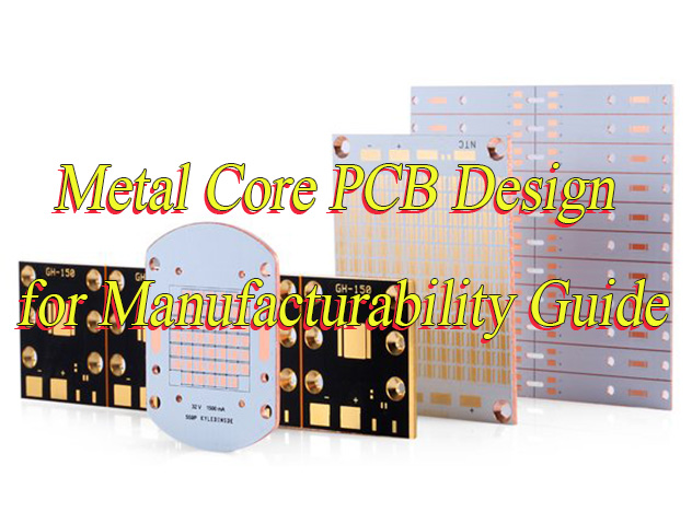
Metal Core Printed Circuit Boards (MCPCBs) are widely used in high-power applications like LED lighting, automotive systems, and power electronics. They offer superior thermal management compared to standard FR4 PCBs, but several variables impact their final pricing. Whether youâre prototyping or placing a volume order, understanding these factors helps you make informed decisions and avoid unexpected costs.
At Best Technology, we manufacture a wide range of MCPCBs tailored to customer requirements. Below, weâve broken down the main elements that influence pricing so you can better evaluate your design options.
Key Technical Factors That Affect MCPCB Pricing
1. Board Dimensions
Size is the starting point for cost evaluation. For non-rectangular shapes like circles, pricing is based on the longest two sidesâtypically the diameter for round boards. Larger boards require more base material and longer processing time, which increases the unit price.
2. Copper Thickness
Copper thickness directly affects both thermal performance and cost. We offer standard and high-current options, including 0.5 OZ, 1 OZ, 2 OZ, 3 OZ, up to 8 OZ. Thicker copper enhances current-carrying capacity but also raises the complexity and expense of manufacturing.
3. Thermal Conductivity
A higher thermal conductivity helps to dissipate heat more efficiently. For example, 3W/m·K materials offer better heat transfer but are more expensive than standard options. The choice often depends on the power density of your application.
4. Surface Finishing
We support finishes such as HASL_LF (lead-free hot air leveling), OSP (Organic Solderability Preservative), and ENIG (Electroless Nickel Immersion Gold). ENIG is the premium choice due to its excellent solderability and oxidation resistance, though it comes at a higher cost.
5. Board Thickness
The most common MCPCB thickness is 1.6mm ±10%, which meets most design standards. Boards thinner than 1mm or thicker than 2mm will cost more due to non-standard processing. Our maximum capacity reaches 4.0mm ±10% for specific projects.
6. Solder mask Type and Color
Solder mask adds not only a protective layer but also an aesthetic touch. We offer white, black, blue, green, and red options. For high-end applications like LED boards, Taiyo solder mask is preferred for its excellent reflectivity, though it is priced higher than regular options.
7. Stack-Up and Construction
The complexity of the PCB stack-up has a big impact on both cost and manufacturing time. Single-layer boards are simpler and cheaper, while multi-layer, double-sided, or heat sink-integrated boards increase the number of processes, materials, and quality inspections required.
MCPCB Types We Offer
Our company specializes in producing a wide range of MCPCB types to suit various thermal and mechanical requirements:
Single Layer MCPCB
Two Layers MCPCB
Double-Sided MCPCB
Multi-Layer MCPCB
Chip-on-Board (COB) MCPCB
Heat Sink Integrated MCPCB
Each type is customizable to your exact application needsâwhether you’re building high-power LED lighting, automotive electronics, or power conversion devices.
How to Choose the Right Parameters Without Overspending?
When planning your MCPCB project, it’s essential to balance performance requirements with budget constraints. Here are a few suggestions:
Match copper thickness to your current needs â don’t over-specify if lower OZ will suffice.
Select surface finishing based on reliability needs â use ENIG for sensitive components, OSP for more budget-friendly builds.
Ask about solder mask options early â especially for LED projects requiring high reflectivity.
Consider standard thicknesses â unless your application has unique structural or thermal demands.
Let us help with stack-up decisions â especially for complex or multi-functional boards.
At Best Technology, we guide you through each stage of development, offering design support, material recommendations, and volume-based quotations that match your project goals.
Need help optimizing your MCPCB design for performance and cost?
Contact our team today for a fast, professional quote and expert guidance tailored to your application.
PCB contract manufacturing is a process where companies outsource the production of printed circuit boards to a third-party manufacturer. This includes not just making the board, but also assembling components, running functional tests, and sometimes even final product packaging. It allows companies to focus on core tasks like product development and marketing, while the technical side of electronics production is handled by experts.
At its core, PCB contract manufacturing saves time, reduces production costs, and ensures consistency in quality. For startups and global electronics brands alike, finding a dependable contract manufacturer can significantly boost speed-to-market and reduce project risks.
What Is PCB Contract Manufacturing
Our Printed Circuit Board Services
At Best Technology, we offer a complete range of services under one roof. Whether you’re developing a new electronic product or scaling up production, we handle everything from the initial design to final functional testing. Hereâs what we bring to the table:
PCB Layout & Design
We help you start from scratch or improve your existing Gerber files. Our layout team is experienced in high-density routing, impedance control, and EMC-compliant designs. With tools like Altium Designer and CAD, we ensure accurate and efficient PCB layouts tailored to your project needs.
OEM & ODM PCB Manufacturing
Whether you need OEM or ODM service, we have the capability to take your concept and turn it into a working product. Our engineering team collaborates closely with clients to deliver custom solutions that are production-ready.
Electronic Components Assembly
From SMT (Surface Mount Technology) to through-hole assembly, our facility is equipped for full-scale PCBA (Printed Circuit Board Assembly). We support both leaded and RoHS-compliant assembly and offer automated inspection (AOI), X-ray, and BGA rework services to guarantee every joint is solid and reliable.
Wire Harness Assembly
We also supply PVC/PE/TPU/LZSH hook-up wire, flat cable, connector wire harness for machinery equipment, and cables for the field of electronic appliances, DC power supply, audio video devices, toys, medical equipment, communication devices, electrician & electrical, computer accessories cable, and so on.
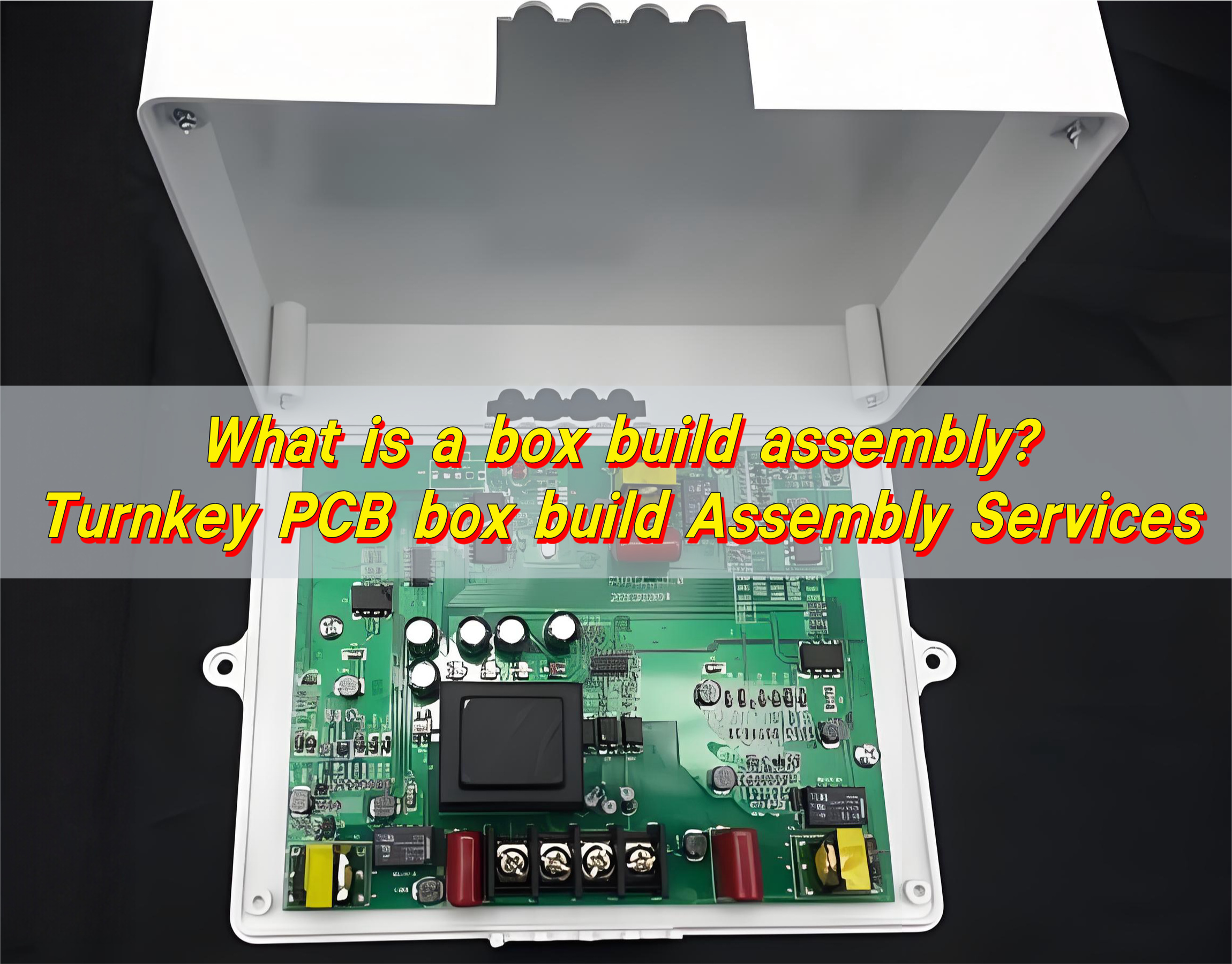
Box Building Assembly
We donât stop at the board level. If you need enclosure integration, cable harnessing, or full unit assembly, our box building assembly service is available. This end-to-end solution simplifies your supply chain and gives you more control over the finished product.
Functional Testing
We provide full functional testing based on your test procedure or help you develop one. This includes power-on tests, signal integrity verification, and custom fixture testing. We ensure your board works perfectly before it reaches your customers.
Our Printed Circuit Board Services
What PCBs We Can Fabricate?
Our team at Best Technology specializes in a wide range of printed circuit board types. No matter your projectâs complexity or environment, weâve got you covered. Here are some products that we can make, but not limited to these PCBs.
Extra Thin PCB
For devices that require tight packaging like smart cards, cameras, or medical sensors, we offer ultra-thin PCBs as thin as 0.1mm. These boards maintain strength while saving space.
HDI PCB
High-Density Interconnect (HDI) PCBs support advanced electronics with fine-pitch components, blind and buried vias, and micro-via-in-pad technology. These are perfect for smartphones, tablets, and compact IoT devices.
RF PCB
We manufacture RF (Radio Frequency) PCBs using low-loss materials like Rogers, Taconic, and PTFE laminates. These boards are designed for wireless communication, antennas, and radar systems, where signal clarity matters most.
Heavy Copper PCB & Busbar PCB
When high current is involved, such as in automotive or industrial power supplies, heavy copper and busbar PCBs are necessary. We can produce boards with copper thickness from 2oz to 20oz, ensuring excellent thermal and electrical performance.
Metal Core PCB
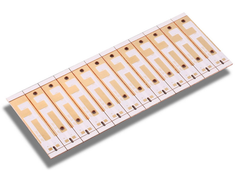
For LED lighting and power conversion applications, our metal core PCBs (MCPCBs) provide efficient thermal dissipation. Aluminum and copper cores are both available depending on your thermal and mechanical needs.
Ceramic PCB
Using materials like aluminum nitride and alumina, ceramic PCBs deliver outstanding heat resistance and insulation. We have mature manufacturing technologies, including: Thick film ceramic PCB, thin film ceramic PCB, AMB ceramic PCB, DBC & DPC ceramic PCB, HTCC & LTCC ceramic PCB.
Flex Circuit & Rigid-Flex PCB
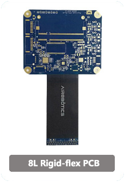
Flex circuits offer excellent bendability, reducing connectors and saving space. Rigid-flex PCBs combine the best of both worlds and are widely used in wearables, drones, and other portable electronics.
High-Speed PCB
We design and produce high-speed PCBs with controlled impedance, low-loss materials, and proper stack-ups. These are ideal for applications like 5G networks, servers, and high-frequency digital communication.
High TG PCB
When operating temperatures exceed 170°C, High-TG (glass transition temperature) PCBs are the right choice. These boards are more stable thermally and mechanically, perfect for automotive and industrial applications.
IC Substrate
We also support packaging solutions with IC substrates that act as a bridge between chips and PCBs. Our substrates offer fine-line traceability and are used in semiconductor packaging.
Ceramic Packages
Ceramic packages provide superior hermetic sealing and thermal cycling endurance. These are used to package sensitive ICs in defense, aerospace, and critical medical applications.
FR4 PCB Capability in Best Technology
At Best Technology, we offer a wide range of FR4 PCBs â the most common material in the PCB industry â from consumer electronics to industrial control systems and automotive electronics. Whether it’s single-sided, double-sided, or multi-layer (up to 40 layers), we provide:
✅ General Capabilities
Layer Count: 1â40 layers
Board Size: Up to 580mm Ă 1200mm
Board Thickness: 0.2mm to 3.2mm
Copper Thickness: 0.5oz to 6oz (outer), 0.5oz to 3oz (inner)
Finished Hole Size: â„ 0.10mm
Minimum Line Width / Spacing: 3mil / 3mil (0.075mm)
Aspect Ratio: Up to 12:1
Impedance Control: ±10% or better
✅ Material Options
Standard FR4: Tg135°C
High-TG FR4: Tg170°C to Tg180°C
Halogen-Free FR4: Environmentally friendly for RoHS/REACH applications
Low Dk/Df FR4: For better signal performance in high-speed circuits
✅ Surface Finishes
HASL (Hot Air Solder Leveling) â Leaded & Lead-free
With a monthly capacity of over 30,000 square meters and a 98% on-time delivery rate, our FR4 line is built to serve both prototypes and mass production.
Certifications & Quality Assurance in PCB Manufacturing
At Best Technology, quality isnât just a goal â itâs a standard built into every step of our manufacturing process. To ensure compliance with international regulations and industry-specific requirements, we maintain a comprehensive set of certifications, including:
IPC Standards Compliance – IPC-A-600 and IPC-A-610 Class 2 & Class 3 for PCBfabrication and assembly
One-Stop High-Quality PCB Contract Manufacturer
When you’re looking for a reliable partner to handle your PCB contract manufacturing, Best Technology is ready to deliver more than just boards. We provide full-service support â from design to delivery â with speed, precision, and attention to detail.
We offer a complete solution that includes PCB fabrication, components sourcing, assembly, testing, and even box build â all under one roof. That means you donât have to juggle multiple suppliers or waste time coordinating between factories. You get a dedicated project manager, clear communication, and consistent quality from start to finish.
Engineering Support: this isnât traditional engineer support, in Best Technology, every sales are engineer, they are professional so that can save much time on design communication and can give you the best solutions.
Fast Turnaround: we offer quick-turn prototyping (as fast as 24 hours) and competitive lead times for volume production.
Global Shipping: Whether youâre in the US, Germany, Japan, or Australia, we ship your orders promptly with DHL, FedEx, UPS, air & ocean shipment.
Traceability System: Our ERP system keeps detailed records for every board we produce, offering transparency and traceability.
WIP Update Every Week: Every customer can enjoy one-to-one sales-assistant service, they will update the product status & share videos every week for you, so that you can closely to your PCBs.
Cost-Effective Solutions: With advanced production lines and a mature supply chain, we provide cost-effective options without sacrificing quality.
PCB contract manufacturing can significantly reduce your product development cycle and overhead. By partnering with a professional and certified provider like Best Technology, you ensure every step â from PCB layout to functional testing â meets your project goals with precision and speed.
Whether you need a simple FR4 board or a high-performance ceramic PCB, our comprehensive services and commitment to quality make us a trusted choice for businesses around the world.
Frequently Asked Questions
1. What industries does Best Technology serve?
We serve a broad range of industries including medical, automotive, aerospace, telecom, and consumer electronics.
2. Can Best Technology support low-volume or prototype orders?
Yes, we support both small-batch prototypes and high-volume production with flexible minimum order quantities.
3. Do you offer component sourcing services?
Absolutely. We have partnerships with authorized distributors to source genuine components and manage the BOM for you.
4. What file formats do you accept for PCB layout?
We accept Gerber, ODB++, and other formats such as Altium, Eagle, and CAD-based files.
5. How can I request a quote for PCB contract manufacturing?
Simply send your files and requirements via our online form or email, and our sales team will get back to you within 24 hours.