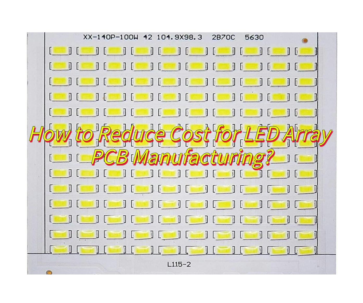
Curious about automotive LED PCB? Dive into their structure, applications, sourcing strategies, quality standards, production optimizations, and critical FAQs of automotive LED PCB manufacturing.
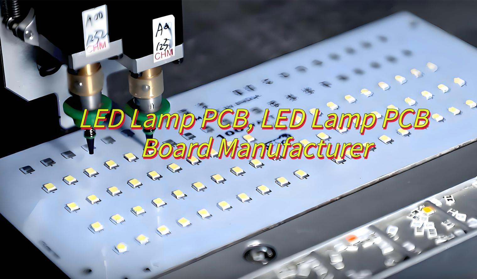
EBest Circuit (Best Technology) specializes in automotive LED PCB manufacturing, holding IATF 16949 certification for automotive quality compliance. We deliver prototype samples within 48 hours, backed by streamlined logistics and a dedicated engineering team. Our products undergo strict IPC Class 3 testing, including AOI and X-ray inspections, ensuring reliability in extreme thermal/vibration conditions. With 8+ years of automotive project experience, we support global Tier 1 suppliers in headlight, taillight, and interior lighting PCBs. Advanced SMT lines enable ±0.03mm placement accuracy, while custom solutions optimize designs for EMI shielding and heat dissipation. Global clients benefit from 24/7 technical support and NPI-to-mass-production continuity. If you have any request for automotive LED PCB, welcome to contact us sales@bestpcbs.com
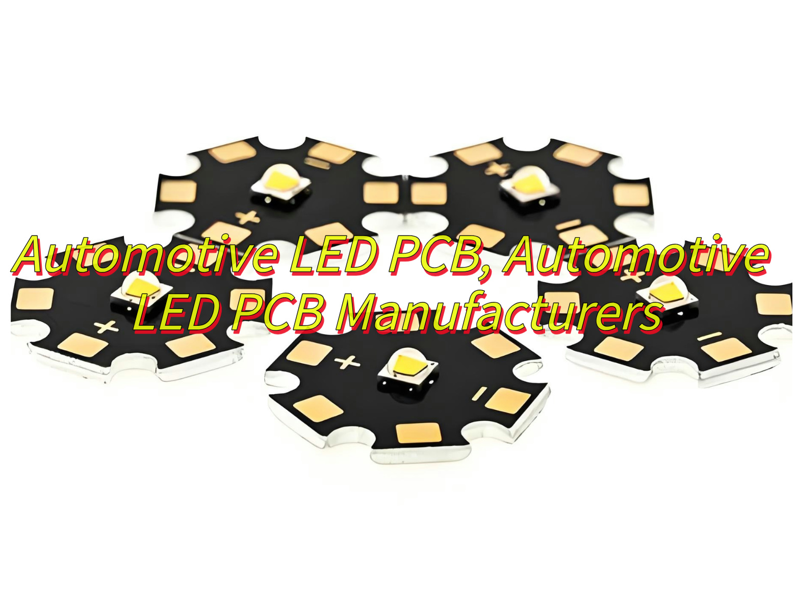
What Is Automotive LED PCB?
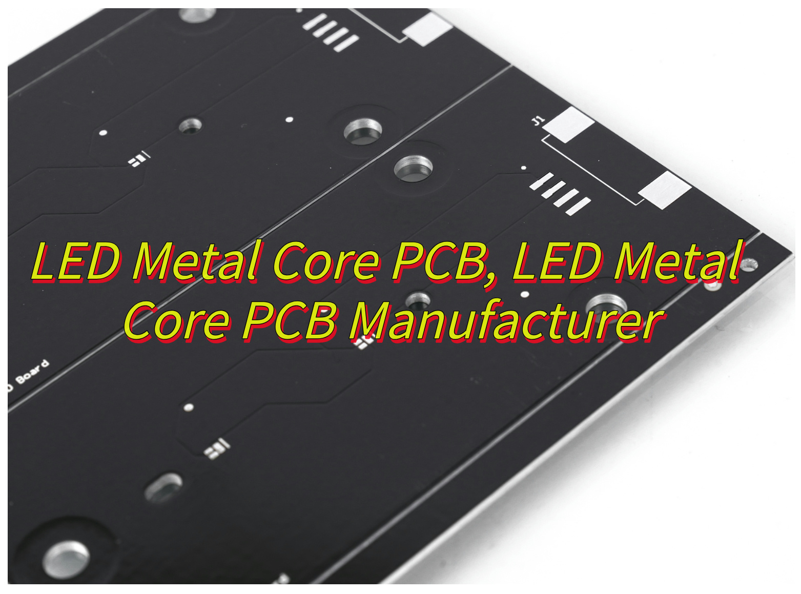
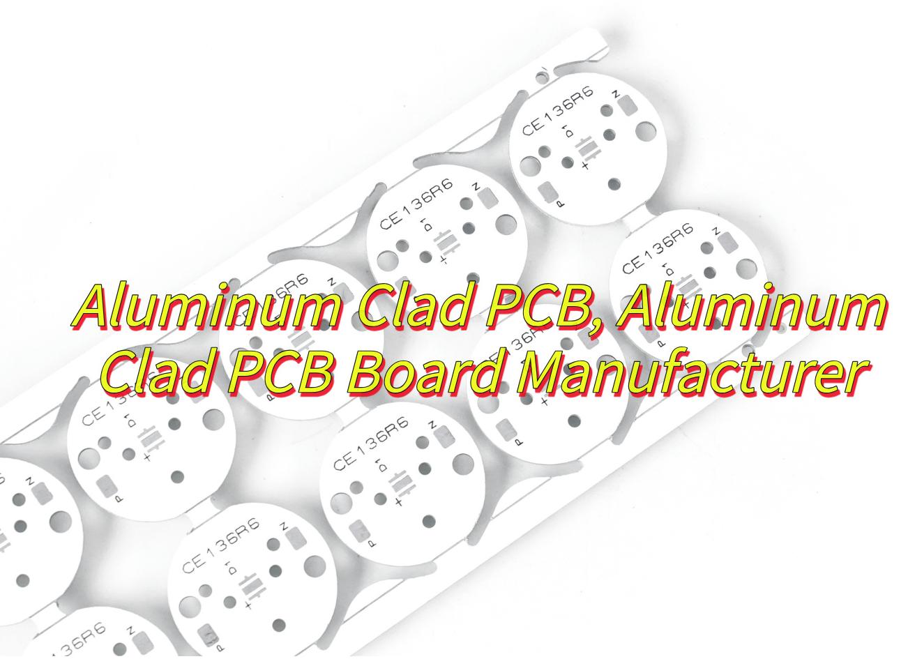
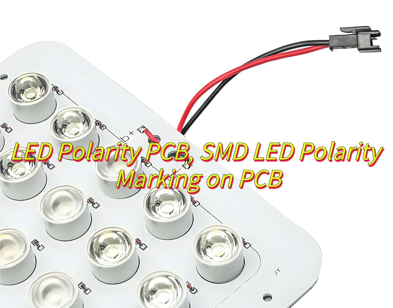
An Automotive LED PCB is a printed circuit board designed for powering and managing LED lighting systems in vehicles, integrating heat dissipation mechanisms to counteract high thermal loads and current regulation circuits to maintain stable light output. It utilizes aluminum-core materials for rapid heat transfer and durable construction to endure automotive environmental stresses such as temperature extremes and vibrations, ensuring long-term reliability and energy-efficient operation of LED components.
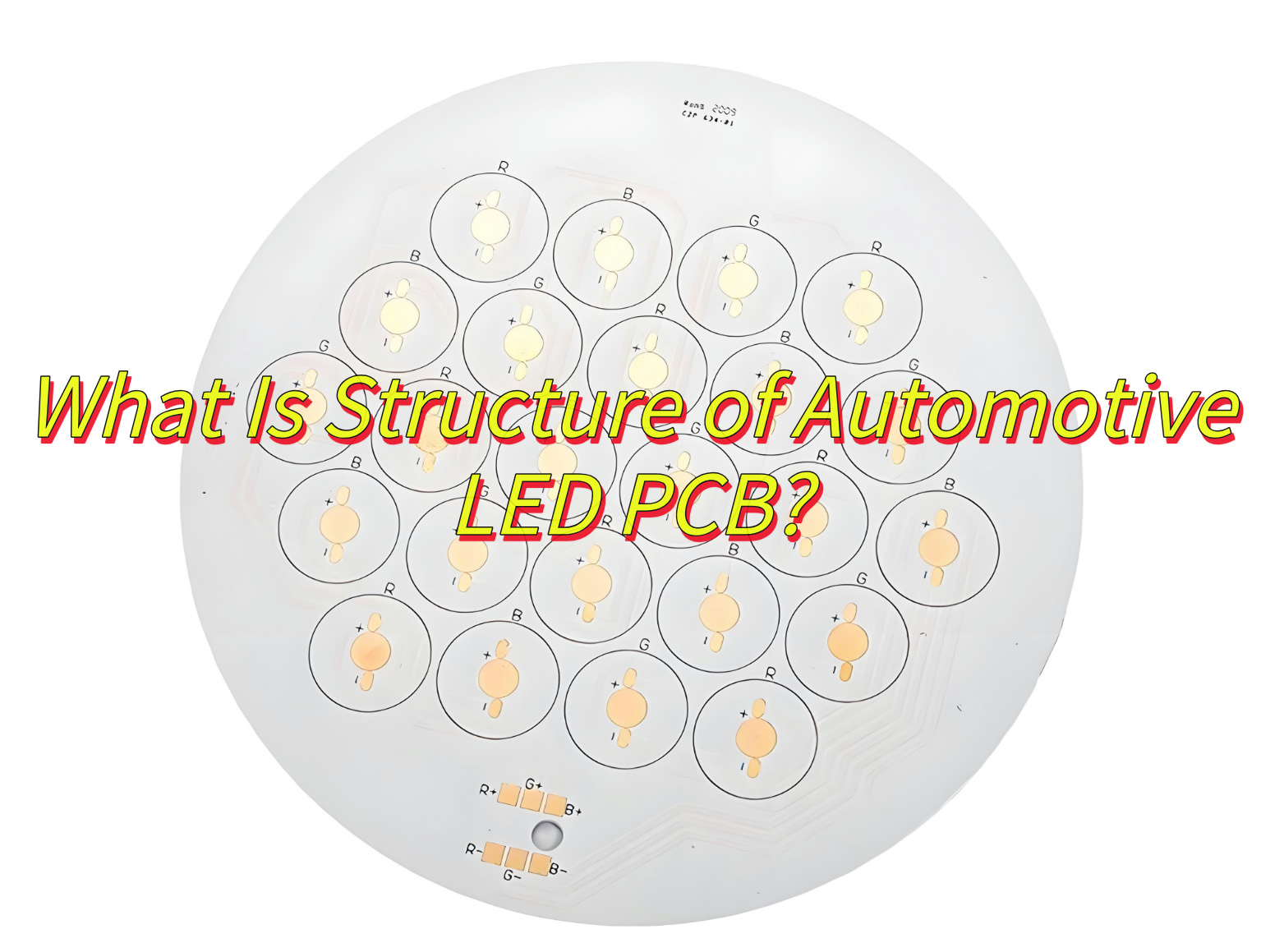
What Is Structure of Automotive LED PCB?
Structure of Automotive LED PCB:
- Substrate Layer: Typically made of aluminum-based materials (e.g., aluminum core) for high thermal conductivity, supporting circuit components and heat dissipation.
- Conductive Layer: Composed of copper traces to transmit electrical signals and power to LED components.
- Insulation Layer: A dielectric material (e.g., thermally conductive polymer) isolating the conductive layer from the substrate while allowing heat transfer.
- Solder Mask: Protective coating over copper traces to prevent oxidation and short circuits.
- Thermal Management Features: Metal cores, heat sinks, or thermal vias to direct heat away from LEDs.
- Component Mounting Areas: LED chips, driver ICs, and resistors soldered onto pads with high-temperature-resistant adhesives.
- Connector Interfaces: Pins or terminals for integrating with vehicle wiring systems.
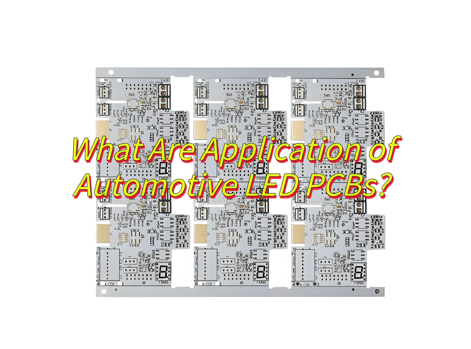
What Are Application of Automotive LED PCBs?
Applications of Automotive LED PCBs:
- Headlights & Fog Lights: Deliver high-intensity illumination with low power consumption, enhancing nighttime visibility and safety.
- Tail Lights & Brake Lights: Provide instant, crisp signaling for rear drivers, improving reaction times.
- Interior Lighting: Enable customizable ambient lighting, dashboard backlighting, and trunk/cargo area illumination.
- Turn Signals & Hazard Lights: Ensure bright, dynamic flashing patterns for clear directional communication.
- Instrument Clusters: Power high-resolution displays for speedometers, fuel gauges, and diagnostic alerts.
- Advanced Driver-Assistance Systems (ADAS): Support sensors like LiDAR and cameras for features like lane departure warnings.
- Charging Port Indicators: Signal electric vehicle (EV) charging status with color-coded LED patterns.
- Dynamic Exterior Lighting: Enable adaptive beam patterns and animated welcome sequences for premium vehicles.
How to Find An Automotive LED PCB Factory?
This is how to Find an Automotive LED PCB Factory:
- B2B Platforms: Use platforms like Alibaba, Global Sources, or Industry Stock to filter factories by location, certifications, and production capacity.
- Trade Shows: Attend automotive electronics exhibitions to meet suppliers directly and assess product samples.
- Regional Manufacturing Hubs: Target factories in regions like Guangdong (China), or Southeast Asia for cost-effective, scalable production.
- Certification Databases: Verify factories with automotive standards (IATF 16949, ISO 9001) via official certification registries.
- Referral Networks: Contact industry associations or existing buyers for trusted manufacturer recommendations.(like EBest Circuit (Best Technology))
- Direct RFQ Process: Submit detailed specifications to multiple factories via email or platforms to compare quotes and lead times.
- Factory Audits: For critical partnerships, schedule on-site visits to evaluate equipment, quality control, and compliance.

Where to Find the Latest Automotive LED PCB Pricelist?
Where to Find the Latest Automotive LED PCB Pricelist:
- Manufacturer Websites: Check official sites for downloadable catalogs or contact sales teams for customized quotes.
- B2B Platforms: Use platforms like Alibaba or Made-in-China to request pricelists via RFQ (Request for Quotation) tools.
- Industry Reports: Subscribe to market research reports (e.g., IDC) for pricing trends and supplier comparisons.
- Direct Inquiries: Email factories with detailed specifications (volume, layers, certifications) to obtain tailored pricing.
- Distributor Networks: Contact authorized distributors for bulk discounts and regional pricing insights.
- Trade Show Exhibitors: Collect pricelists from factory booths during automotive electronics exhibitions.
- Online Forums: Join industry groups (e.g., LinkedIn, Reddit) to gather crowdsourced pricing data from peers.
How to Identify Quality Automotive LED PCB Manufacturers?
How to Identify Quality Automotive LED PCB Manufacturers:
Certifications & Compliance:
- Look for ISO/TS16949 (automotive quality management), ISO 9001, and AEC-Q qualifications.
- Verify compliance with RoHS, REACH and regional environmental standards.
Production Expertise:
- Prioritize manufacturers with 10+ years’ experience in wholesale automotive LED PCBs production.
- Check partnerships with Tier 1 suppliers or OEMs (e.g., Bosch, Continental).
Quality Control Systems:
- Assess inspection processes: AOI (Automated Optical Inspection), X-ray testing, and SPC (Statistical Process Control).
- Ensure defect rates are below 0.5% and traceability via barcodes or QR codes.
R&D & Engineering Capabilities:
- Confirm in-house design teams for high-layer PCBs (e.g., 10+ layers), HDI (High-Density Interconnect), and thermal management.
- Evaluate support for DFM (Design for Manufacturability) and DFA (Design for Assembly).
Client Validation:
- Request case studies or contact references for feedback on on-time delivery, rework rates, and field failures.
Sample Testing:
- Subject prototypes to thermal cycling (-40°C to 125°C), vibration, and humidity tests.
- Validate LED compatibility and EMC (Electromagnetic Compatibility).
Equipment & Technology:
- Ensure factories use advanced machinery
- Check for Class 10,000 cleanrooms for critical processes.
Technical Support:
- Confirm availability of technical support and DMF analysis services.
How Does an Automatic LED PCB Loader Improve Production Efficiency?
Reduced Labor Dependency:
- Eliminates manual loading/unloading, cutting human error and operator fatigue.
Faster Cycle Times:
- Enables continuous feeding at speeds exceeding 500 boards/hour, syncing with SMT lines.
Precision Handling:
- Uses vision systems and sensors to align PCBs with ±0.1mm accuracy, reducing misplacements.
24/7 Operation:
- Runs uninterrupted, maximizing equipment utilization during off-peak hours.
Seamless Integration:
- Connects with MES (Manufacturing Execution Systems) for real-time production tracking and inventory management.
Enhanced Throughput:
- Minimizes idle time between processes, boosting overall line efficiency by 20–40%.
Data-Driven Optimization:
- Generates logs for analyzing bottlenecks, enabling predictive maintenance and process tweaks.
Scalability:
- Supports high-mix/low-volume production with quick tool-free adjustments for different PCB sizes/shapes.
FAQs of Automotive LED PCB Manufacturing
- Q: How to prevent solder joint defects in high-vibration environments?
A: Use void-free soldering with flux optimized for thermal shock, and add underfill epoxy to reinforce connections. - Q: What causes LED “thermal runaway” on PCBs?
A: Inadequate heatsink design or poor copper distribution. Integrate thermal vias and aluminum-backed PCBs for efficient heat dissipation. - Q: How to mitigate electromagnetic interference (EMI)?
A: Implement ground planes, differential pair routing, and add shielding cans around LED clusters. - Q: Why do PCBs delaminate under thermal cycling?
A: Mismatched CTE (Coefficient of Thermal Expansion) between layers. Use low-CTE prepregs and thermally matched substrates. - Q: How to ensure compatibility with automotive fluids/chemicals?
A: Select FR-4 TG170+ or polyimide materials, and perform ASTM D543 resistance testing against oils, fuels, and coolants.