Why settle for outdoor LED screen PCB? This guide covers its types, benefits, durability hacks, and expert tips to evaluate manufacturers for reliable, weatherproof LED PCBs tailored to global demands.
EBest Circuit (Best Technology) specializes in outdoor LED screen PCB engineered for extreme outdoor environments. Our products feature IP68 waterproofing, corrosion-resistant coatings, and industrial-grade components (e.g., aluminum substrates) to ensure 10+ years of reliable operation under -40°C to +85°C temperatures. With ISO 9001, IPC, and UL certifications, we enforce strict quality controls by AOI, X-ray inspection, and thermal stress tests to eliminate defects. Customizable pixel pitches (P3–P20) and modular designs enable quick repairs, minimizing downtime. Contact us today for competitive pricing and samples if you have any request for outdoor LED screen PCBs: sales@bestpcbs.com
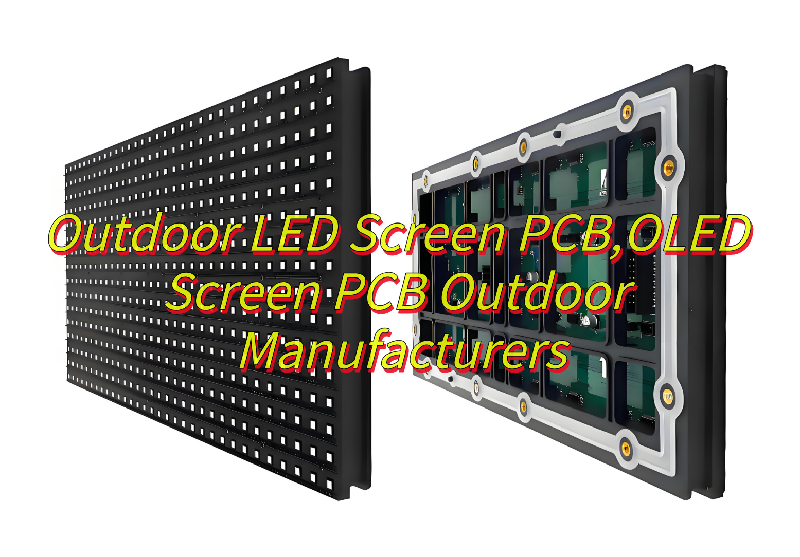
What Is Outdoor LED Screen PCB?
An outdoor LED Screen PCB (Printed Circuit Board) is the essential component that powers and manages LED modules in outdoor display systems. Built with weather-resistant materials like fiberglass and protective coatings, it ensures reliable operation under challenging conditions such as rain, extreme temperatures, and sunlight. The PCB regulates electrical connections and data signals, enabling vibrant, long-lasting visuals for billboards, stadiums, and public signage.
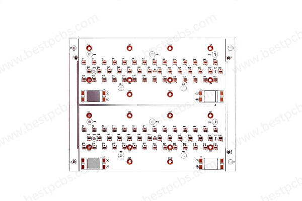
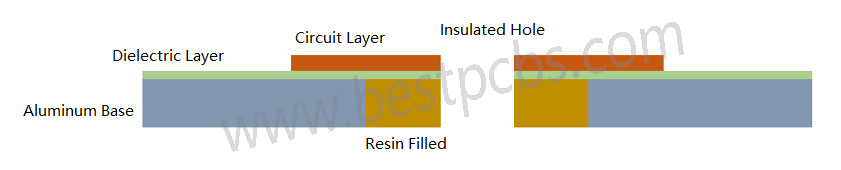
What Is Structure of Outdoor LED Screen PCB?
Here’s a clear breakdown of outdoor LED Screen PCB’s structural elements:
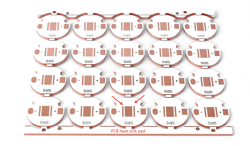
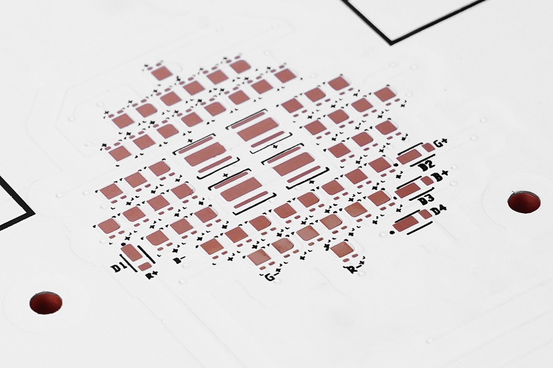
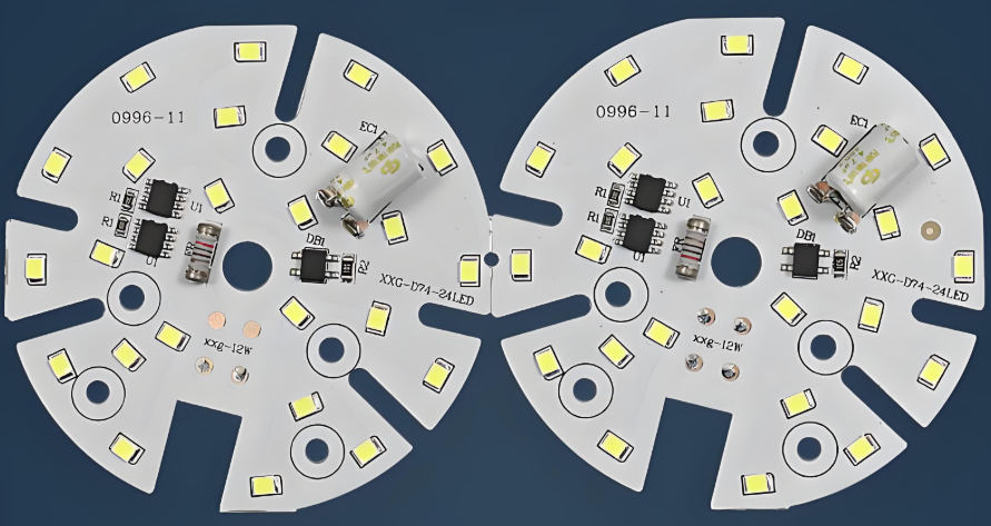
- Carrying and connecting lamp beads: There are multiple LED chips welded on the PCB, which determine the basic color, brightness, viewing angle and life of the display screen, etc.
- Electrical connection: The PCB connects various electronic components through wires or circuit patterns to ensure the transmission of current and signals.
- Support structure: The PCB is usually connected to the bottom shell through positioning columns to form the basic structure of the display screen.
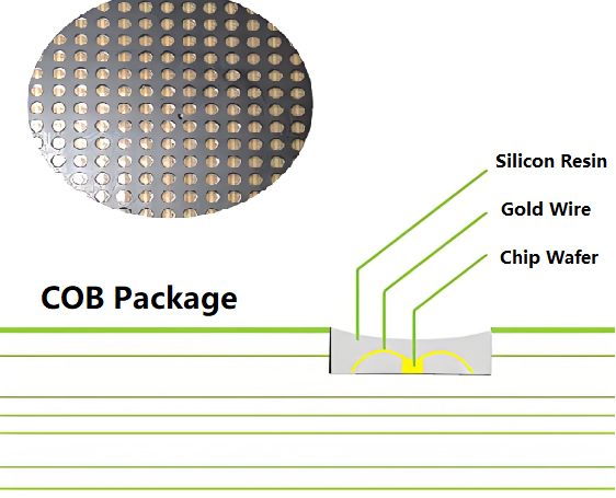
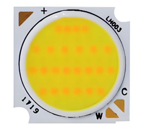
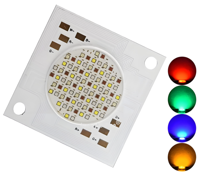
- Display unit: It is composed of lamp beads (such as SMD or COB packaging) and determines the display effect of the display screen.
- Control system: It includes sending cards and receiving cards, which are responsible for the processing and distribution of video signals.
- Structural part: Such as the box, frame and back cover, to ensure the stability of the display screen and protect the internal structure.
- Power supply system: Provides a stable DC power supply to ensure the normal operation of the display screen.
- Signal transmission system: Such as network cables or optical fibers to ensure efficient data transmission.
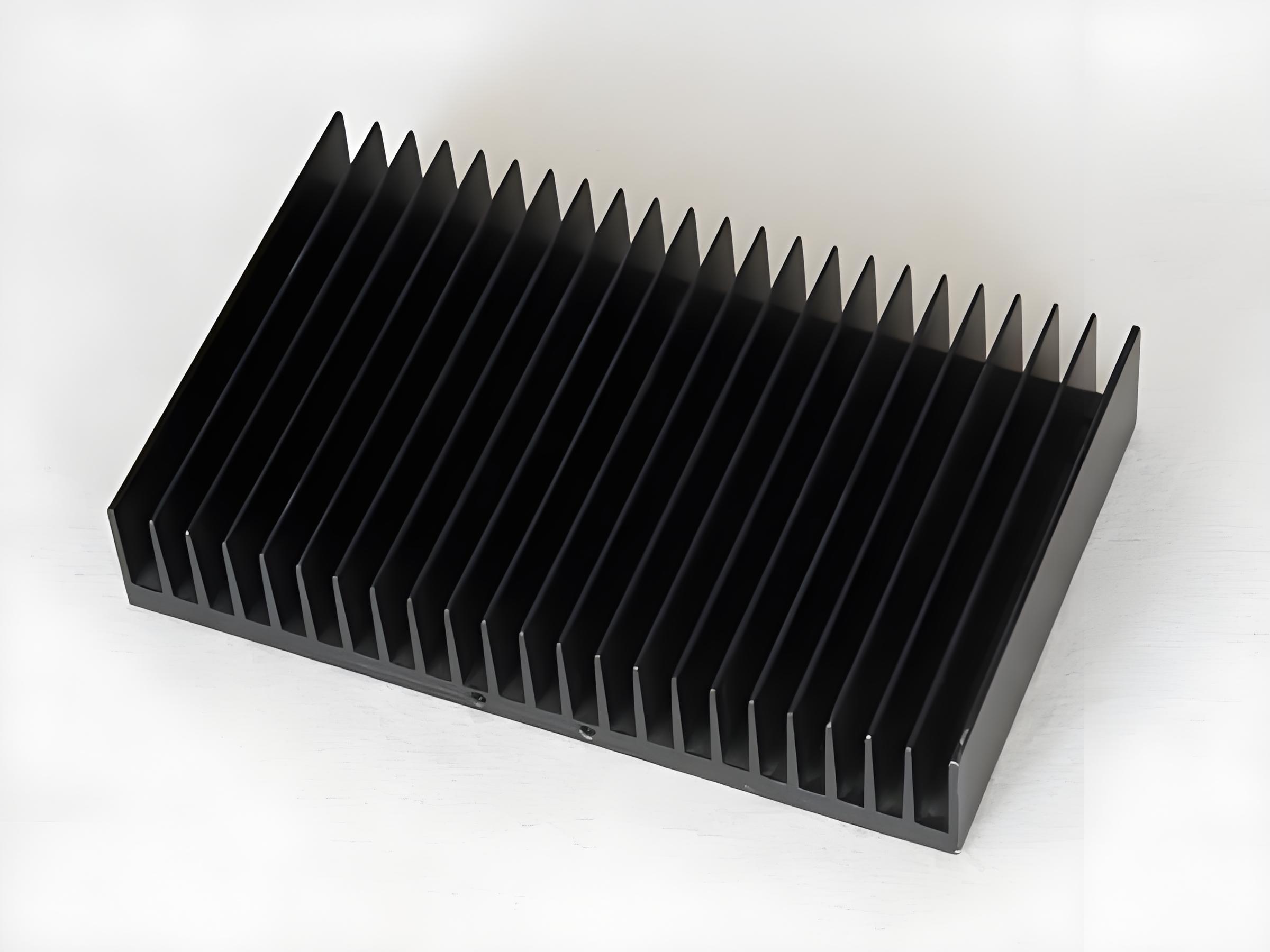
- Cooling system: Including cooling fans, heat sinks and air conditioners, etc., to maintain the working temperature of the display screen.
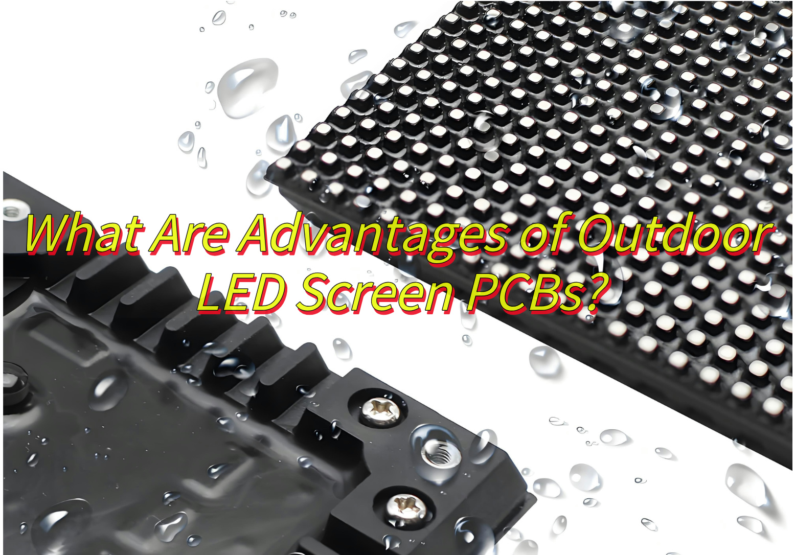
What Are Advantages of Outdoor LED Screen PCBs?
Benefits of LED Screen PCBs:
- Weatherproof Design – Outdoor LED PCBs are built with IP65/IP67 waterproof ratings and corrosion-resistant coatings. This protects circuits from rain, dust, and humidity, ensuring stable performance in harsh conditions like coastal areas or rainy climates.
- High Brightness and Visibility – These PCBs use 8000–10,000 nits brightness LEDs and anti-glare surface treatments. This guarantees clear visibility even under direct sunlight, making them ideal for billboards, stadiums, or traffic signs.
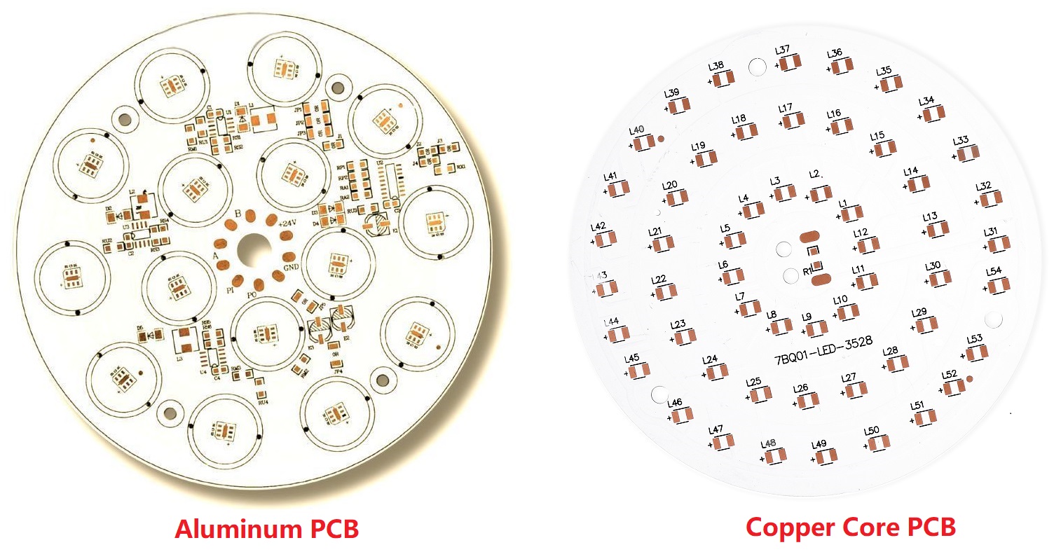
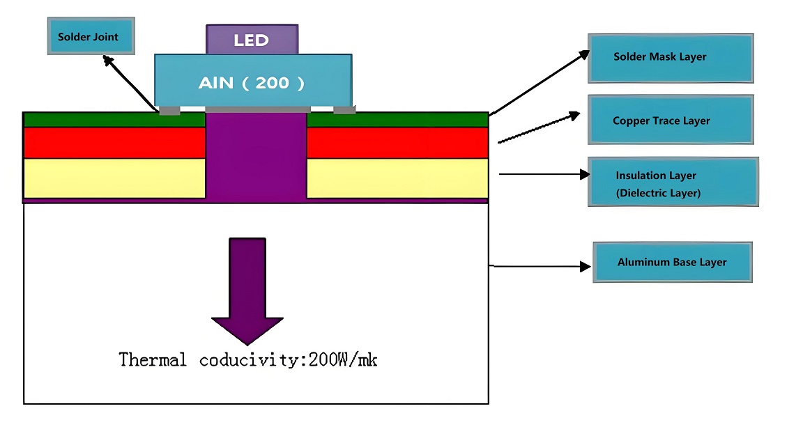
- Heat Dissipation Technology – Advanced thermal management materials (e.g., aluminum substrates) and heat sinks prevent overheating. This extends component lifespan by 20–30% compared to standard PCBs, reducing long-term maintenance costs.
- Shock and Vibration Resistance - Reinforced solder joints and impact-resistant materials protect against physical stress during transport or installation. This minimizes damage risks in high-wind zones or busy urban areas.
- Energy Efficiency – Low-power LED chips and smart driver ICs cut energy consumption by up to 40%. This aligns with global sustainability goals while lowering operational costs for 24/7 displays.
- Longevity in Extreme Temperatures – Components rated for -40°C to +85°C ensure reliable operation in freezing winters or scorching summers. This durability suits regions with wide temperature fluctuations.
- Easy Maintenance and Repairs – Modular designs allow quick replacement of faulty sections without shutting down the entire display. This reduces downtime for advertisers or event organizers.
- Customizable Pixel Pitches - Options ranging from P3 to P20 let buyers choose resolution levels based on viewing distances. For example, P10 is cost-effective for highway billboards, while P3 suits close-up retail displays.
How Do Outdoor LED Screen PCBs Handle Extreme Weather Conditions?
How Outdoor LED Screen PCBs Withstand Extreme Weather
Outdoor LED displays must endure harsh elements like rain, heat, cold, and humidity. Here’s how their PCBs are engineered to survive:
Waterproof Construction
- Sealed PCB edges and conformal coatings block moisture infiltration.
- Waterproof connectors and gaskets protect power and data interfaces.
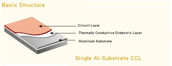
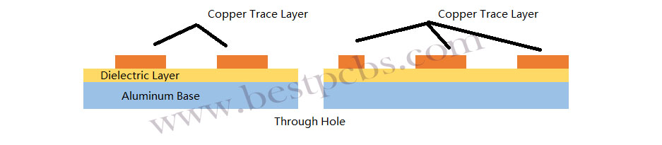
Temperature-Resistant Materials
- Substrates like aluminum or ceramic PCBs withstand thermal expansion without warping.
- Components rated for extreme temperatures (-40°C to 80°C) maintain performance in cold or heat.
Advanced Thermal Management
- Heat sinks, thermal pads, and via arrays dissipate heat generated by high-brightness LEDs.
- Thermal shutdown circuits prevent overheating during prolonged sun exposure.
UV-Resistant Coatings
- Specialty paints or epoxy layers shield PCB surfaces from solar radiation damage.
- UV-stabilized materials prevent color fading in LED packages.
Corrosion-Proof Design
- Nickel-plated copper traces resist oxidation in coastal or industrial environments.
- Stainless steel screws and brackets prevent rusting in wet conditions.
Robust Mechanical Structure
- Reinforced PCB edges and mounting holes prevent cracking from wind-induced vibrations.
- Shock-absorbing gaskets protect against physical impacts during storms.
Electrical Surge Protection
- Built-in TVS diodes and surge suppressors safeguard against lightning strikes.
- Isolated grounding systems prevent electrical damage from power fluctuations.
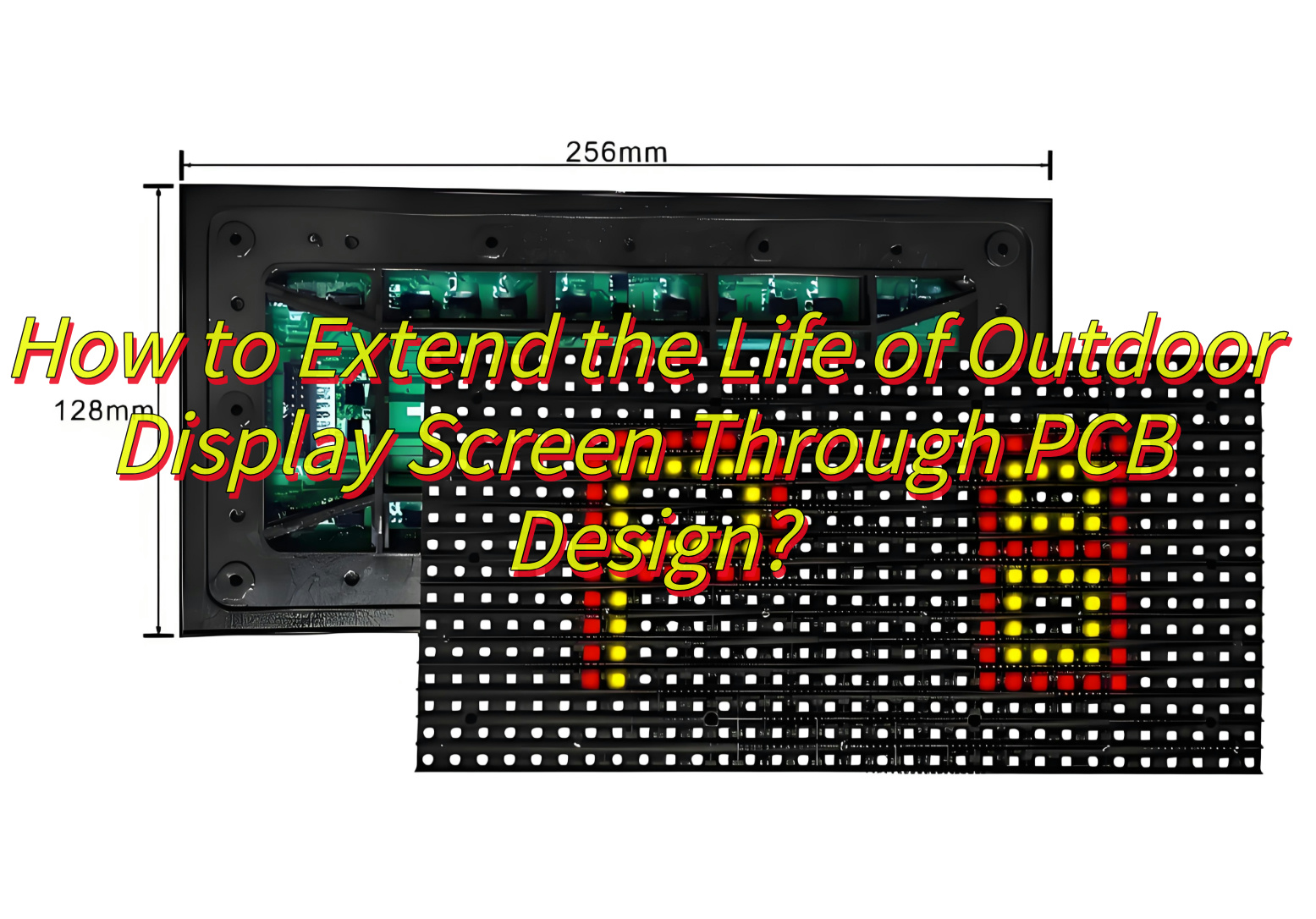
How to Extend the Life of Outdoor Display Screen Through PCB Design?
Here’s how to extend the life of outdoor display screen through PCB design:
Maximizing Outdoor Display Lifespan Through PCB Design
A well-engineered PCB is critical to ensuring long-term durability of outdoor LED screens. Here’s how smart design choices extend their operational life:
Efficient Thermal Management
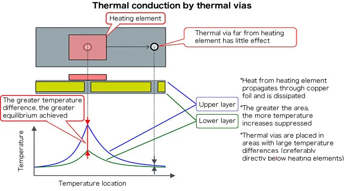
- Integrate heat sinks, thermal vias, and copper layers to dissipate heat quickly.
- Use phase-change materials or liquid cooling channels for high-power applications.
Durability-Focused Materials
- Select aluminum or ceramic substrates for better heat resistance than standard FR-4.
- Apply conformal coatings or potting compounds to protect against moisture and corrosion.
Enhanced Electrical Protection
- Incorporate TVS diodes and fuse protection to absorb voltage spikes during storms.
- Use optocouplers for galvanic isolation between high-voltage and low-voltage circuits.
Stress-Resistant Layout
- Avoid sharp angles in traces to prevent crack propagation under thermal stress.
- Add strain relief features to connector areas to absorb vibration from wind.
Component Selection
- Choose automotive-grade or industrial-grade LEDs and ICs rated for extreme temperatures.
- Use solid electrolytic capacitors with longer lifespan than standard types.
Intelligent Monitoring Systems
- Embed temperature sensors and current monitors to enable predictive maintenance.
- Include diagnostic LEDs or digital interfaces for quick troubleshooting.
Redundant Design Features
- Implement backup power circuits or dual data pathways to ensure continuous operation.
- Use modular PCB sections for easy replacement of damaged areas without replacing the entire panel.
Proactive design choices reduce maintenance costs and downtime. When evaluating suppliers, ask about thermal simulation reports, component lifecycles, and field failure rate data to ensure the PCB design aligns with your long-term operational needs.
How to Verify the Export Experience of Outdoor LED Screen PCB Manufacturers?
Below are how to verify the export experience of outdoor LED screen PCB manufacturers:
- Check Certifications for Global Compliance– Look for certifications like CE, RoHS, or FCC, which indicate adherence to international safety and environmental standards. Manufacturers with these certifications are more likely to handle export documentation and regulations efficiently.
- Review Past Client Projects– Request case studies or client references involving cross-border partnerships. Reliable manufacturers often showcase projects like outdoor billboards or stadium displays with details on logistics and customization.
- Confirm Logistics and Customs Support– Ensure the manufacturer offers services like EXW/FOB shipping terms, pre-shipment inspections, or assistance with customs clearance. These reduce delays and costs for international buyers.
- Evaluate After-Sales Service Networks – Verify if they provide multilingual technical support, warranty coverage, or local repair centers in your region. This ensures timely resolution of post-shipment issues.
- Assess Production Scalability-Test their ability to handle bulk orders during peak seasons. Manufacturers with export experience often have streamlined processes for large-scale PCB production and packaging.
- Validate Quality Testing Processes– Ask for details on IP-rated waterproofing tests, thermal stress trials, or third-party lab reports. Rigorous testing ensures PCBs meet durability requirements for harsh climates.
- Verify Payment Security- Choose manufacturers offering secure payment methods like L/C or Escrow, which protect against fraud in international transactions.
How to Identify the Quality Control Capabilities of Outdoor LED Screen PCB Manufacturers?
Ensuring your supplier maintains rigorous quality standards prevents defects and project delays. Here’s how to evaluate the QC capabilities of outdoor screen PCB manufacturers:
Certification Verification
- Look for ISO 9001 or IATF 16949 certifications indicating structured quality management.
- Confirm compliance with industry-specific standards like IPC-A-610 for PCB assembly.
Inspection Equipment and Processes
- Ask about automated optical inspection (AOI) machines, X-ray testers, and ICT (In-Circuit Test) systems used.
- Review their QC checklist, including solder quality, component placement, and electrical testing.
Defect Rate Transparency
- Request historical data on first-pass yields (FPY) and defect rates (e.g., DPMO metrics).
- Ask how they handle non-conforming products—whether repaired, scrapped, or reworked.
Raw Material Sourcing
- Inquire about supplier qualification processes for materials like copper foil, solder paste, and LED packages.
- Confirm if they use OEM or tier-1 component suppliers.
Client Feedback Analysis
- Seek case studies or performance reports from previous international clients.
- Check third-party review platforms for recurring quality complaints.
Warranty and Returns Policy
- Evaluate the duration and terms of their product warranty.
- Ask about their return material authorization (RMA) process for defective PCBs.
On-Site Audit Option
- For critical projects, schedule a factory tour to inspect production lines and QC labs.
- Interview their QC team about inspection protocols and corrective action procedures.
Poor quality control leads to field failures, repair costs, and brand damage. Prioritize manufacturers with certified systems, transparent metrics, and verifiable case studies of long-lasting installations in demanding outdoor environments
What Technical Parameters Are Required for Customized Outdoor Display PCB?
When specifying custom outdoor LED PCBs, these technical details ensure compatibility and performance:
Display Dimensions and Resolution
- Provide panel width, height, and pixel pitch (distance between LED centers).
- Example: For a P6 screen, PCB layout must match 6mm LED spacing.
Brightness Requirements
- Specify minimum brightness in nits (cd/m²). Outdoor screens typically need 5000-8000 nits.
- Consider automatic brightness adjustment systems for energy efficiency.
Ingress Protection (IP) Rating
- Define required IP rating (e.g., IP65 for waterproof/dustproof).
- Ensure conformal coatings and sealed connectors meet this standard.
Operating Temperature Range
- Specify extreme temperatures the PCB must withstand (e.g., -30°C to 60°C).
- Select components with wider temperature tolerances if needed.
Power Specifications
- Provide input voltage (AC/DC) and maximum power consumption per panel.
- Example: 220V AC input with 300W power budget for a 1m² section.
Interface Compatibility
- List required input interfaces (HDMI, DVI, USB, Ethernet).
- Specify communication protocols (e.g., SPI, I2C) for control systems.
Certification Compliance
- Identify necessary certifications (CE, FCC, ETL, CB) for target markets.
- Ensure electromagnetic compatibility (EMC) and safety standards are met.
Mechanical Specifications
- Provide PCB thickness, mounting hole positions, and edge connector types.
- Include weight limits if panels need reinforced structure.
Color Gamut and Refresh Rate
- Specify color depth (e.g., 16.7 million colors) and refresh rate (Hz) for video quality.
- High refresh rates (>3840Hz) prevent flicker in camera recordings.
In conclusion, that’s all about its LED Screen PCB’s types, benefits, durability hacks, and expert tips to evaluate manufacturers. Welcome to leave a message if you have any issues about LED screen PCB.