Finding the right 24 hour PCB manufacturer can be a game-changer, especially when you need fast turnaround times for your projects. Whether you’re in need of quick turn PCB USA services or a 24 hour PCB solution that meets strict deadlines, choosing the right manufacturer is essential. In this article, we will guide you in selecting the best 24 hour PCB manufacturer for your needs.
As a small and Medium-sized Enterprise, EBest Circuit (Best Technology) provides a diverse PCB portfolio without MOQ requirements. We mainly specialize in 24-hour PCB manufacturing, PCB Design, and PCBA. The geographic distribution of our customers varies from global. By the way, Israel, Germany, and the United States were the countries with the highest export volumes in our company last year. With aerospace quality, our products can be used in extreme temperatures or environments.
Apart from standard rigid FR4 PCB, EBest Circuit (Best Technology) supports multi-layer PCB, like 4 Layer PCB, and some customization PCBs, like HDI PCB, and BGA PCB Assembly. We have nearly 2 Decades of expertise in quick Turn PCB manufacturing, if any questions just feel free to contact EBest Circuit (Best Technology) at sales@bestpcbs.com.
Is There a 24 Hour PCB Manufacturer with No MOQ in China?
If you’re looking for 24 hour PCB manufacturing in China, it’s crucial to understand the capabilities and limitations of different manufacturers. Many companies offer rapid turnarounds, but the challenge often lies in minimum order quantities (MOQ). Some Chinese PCB manufacturers still impose MOQs, especially when production is expedited. However, there are a few companies that cater to low or no MOQ requirements for smaller batch runs. For instance:
EBest Circuit (Best Technology) specializes in fast PCB prototyping with expedited turnaround times. Unlike many manufacturers, we eliminate minimum order quantities (MOQs) for select services, ensuring flexibility for low-volume needs. Our comprehensive PCB solutions include 24-hour lead time options strategically designed to support prototyping phases and small-batch production demands.
Seeed Studio focuses on PCB prototypes and small batches, with the option for fast delivery, offering a solution for companies that need quick results without large commitments.
China offers competitive pricing and fast manufacturing. Working with Chinese 24-hour PCB manufacturers offers convenience and speed for urgent projects.
Can Quick Turn PCB USA Services Handle Complex Assembly in 24 Hours?
A key question many clients have is whether U.S.-based quick-turn PCB services can handle complex assemblies within 24 hours. The answer depends on design complexity, materials, and assembly type. While advanced 24-hour PCB manufacturers in the USA can manage many complex projects, highly intricate designs (e.g., 20+ layers, HDI with blind/buried vias, or specialized substrates) may require extended timelines.
For example, high-speed, high-frequency boards like flexible or multi-layer PCBs often need additional setup. However, 24-hour assembly services can still meet tight deadlines if the manufacturer utilizes advanced automation and robust supply chains, provided component availability and design readiness are confirmed upfront.
What is the Cost of a 24-Hour PCB Manufacturing Service?
The cost of 24-hour PCB manufacturing services varies significantly based on factors such as PCB type (single-sided, double-sided, multi-layer), materials, design complexity, and order quantity. Prototyping costs typically range from 30 to 200+ per board, depending on specifications like layer count (e.g., 4-layer vs. 20-layer) or specialized materials (e.g., high-frequency substrates). Key considerations include:
Design complexity: Multi-layer boards, HDI designs with blind/buried vias, or high-frequency materials increase costs.
Speed: Automated processes and supplier partnerships reduce costs, but advanced designs (e.g., ultra-thin traces) may still require manual adjustments.
Shipping: Express fees for rush orders add to the total cost.
While manufacturers increasingly offer competitive pricing for rapid prototyping, costs remain tied to technical requirements and supply chain efficiency.
24 Hour PCB Manufacturer California
California is home to some of the top 24 hour PCB manufacturers in the USA. These manufacturers are well-equipped to handle urgent orders and can meet the needs of industries ranging from aerospace to medical electronics. Some of the best-known 24 hour PCB manufacturers in California include:
Advanced Circuits: Known for offering rapid PCB manufacturing with an emphasis on quality control and customer support. They cater to both small and large-scale projects, ensuring that your PCB is delivered on time without compromising on quality.
PCB Unlimited: A leading provider of quick turn PCB assembly and 24 hour PCB services. They focus on delivering highly customizable PCB solutions with quick turnarounds.
Sunstone Circuits: Offers a range of PCB manufacturing services, including quick-turn options, to meet the needs of their customers in California and beyond.
California-based manufacturers are particularly beneficial due to their proximity to the tech industry, offering quick turnaround times for critical components.
Where Can I Find Quick-Turn PCB Manufacturing in the USA?
If you’re hunting for quick-turn PCB manufacturers but prefer to explore independently, here are practical channels to streamline your search:
1. Industry-Specific Online Platforms Websites like Thomasnet, Alibaba, or MakerVerse connect businesses with verified PCB suppliers. Use filters like location, certifications, or turnaround time to narrow options.
2. Electronics Trade Shows/Expos Events like IPC APEX EXPO or DesignCon gather PCB manufacturers under one roof. Attendees often get early access to new technologies or limited-time offers.
3. Engineering Forums & Communities Platforms like EEVblog, Reddit’s r/PrintedCircuitBoard, or LinkedIn groups feature candid discussions where engineers share vetted manufacturer recommendations.
4. Local Industry Associations Groups like IPC (Association Connecting Electronics Industries) or regional manufacturing alliances publish directories of certified PCB fabricators.
5. Custom Google Searches Try targeted search terms like “24-hour PCB fabrication USA” + “ISO 9001 certified” or “quick-turn prototype PCB” + “ITAR compliant” to filter results by specific needs.
6. Supplier Referral Programs Ask existing partners (e.g., component distributors or assembly houses) for trusted PCB fabrication referrals—they often have pre-vetted networks.
7. Social Media Outreach Post a detailed RFQ (Request for Quote) on LinkedIn or Twitter, tagging hashtags like #PCBDesign or #ElectronicsManufacturing to attract niche suppliers.
Always verify manufacturers through sample orders or third-party reviews. Check for transparency in pricing, communication responsiveness, and willingness to provide design feedback—these traits often signal a reliable partner for urgent projects.
How to Choose a Reliable 24 Hour PCB Manufacturer?
Choosing the right 24 hour PCB manufacturer is crucial for any project that requires fast delivery. Here are some tips to help you select the best manufacturer for your needs:
Quality Assurance: Ensure that the manufacturer follows strict quality control processes to guarantee the performance and durability of your PCBs.
Experience and Track Record: Look for manufacturers with a proven track record of successfully delivering quick turn PCB USA services, especially for projects similar to yours.
Customer Support: Choose a company that provides clear communication and excellent customer service. This ensures that you get the help you need at every stage of the manufacturing process.
Flexibility: Ensure that the manufacturer can handle varying order sizes and complexities while still meeting your deadline.
Certifications: Look for manufacturers with relevant industry certifications, such as ISO 9001, which demonstrate a commitment to quality and best practices.
What Are EBest Circuit (Best Technology)’s Advantages as a 24 Hour PCB Manufacturer?
EBest Circuit (Best Technology) is a leading 24 hour PCB manufacturer offering rapid prototyping and quick turn PCB assembly services to customers across the USA. Their competitive advantages include:
No MOQ: EBest Circuit (Best Technology) understands that some projects require small-scale production, offering no MOQ for prototyping and low-volume orders.
Fast Turnaround Times: With their advanced manufacturing processes and efficient supply chain management, EBest Circuit (Best Technology) can meet the most urgent deadlines.
Comprehensive Services: From PCB design to assembly, EBest Circuit (Best Technology) provides end-to-end solutions, ensuring that all your requirements are met under one roof.
Global Reach: While based in the USA, EBest Circuit (Best Technology) has strong relationships with international suppliers, offering competitive pricing without compromising on quality.
For businesses that require 24 hour PCB manufacturing with no MOQ and fast delivery, EBest Circuit (Best Technology) offers the perfect combination of expertise, speed, and flexibility.
All in all, in today’s fast-paced tech world, having access to 24 hour PCB manufacturers can make a significant difference in meeting your deadlines and staying competitive. Whether you’re in the USA, China, or California, the right manufacturer can help you deliver quality PCBs quickly and efficiently. By understanding factors such as cost, assembly capabilities, and choosing a reliable manufacturer, you can ensure your project is completed on time. EBest Circuit (Best Technology) offers a unique combination of speed, flexibility, and expertise, making it a trusted partner for all your 24 hour PCB needs. Don’t hesitate to contact us at sales@bestpcbs.com.
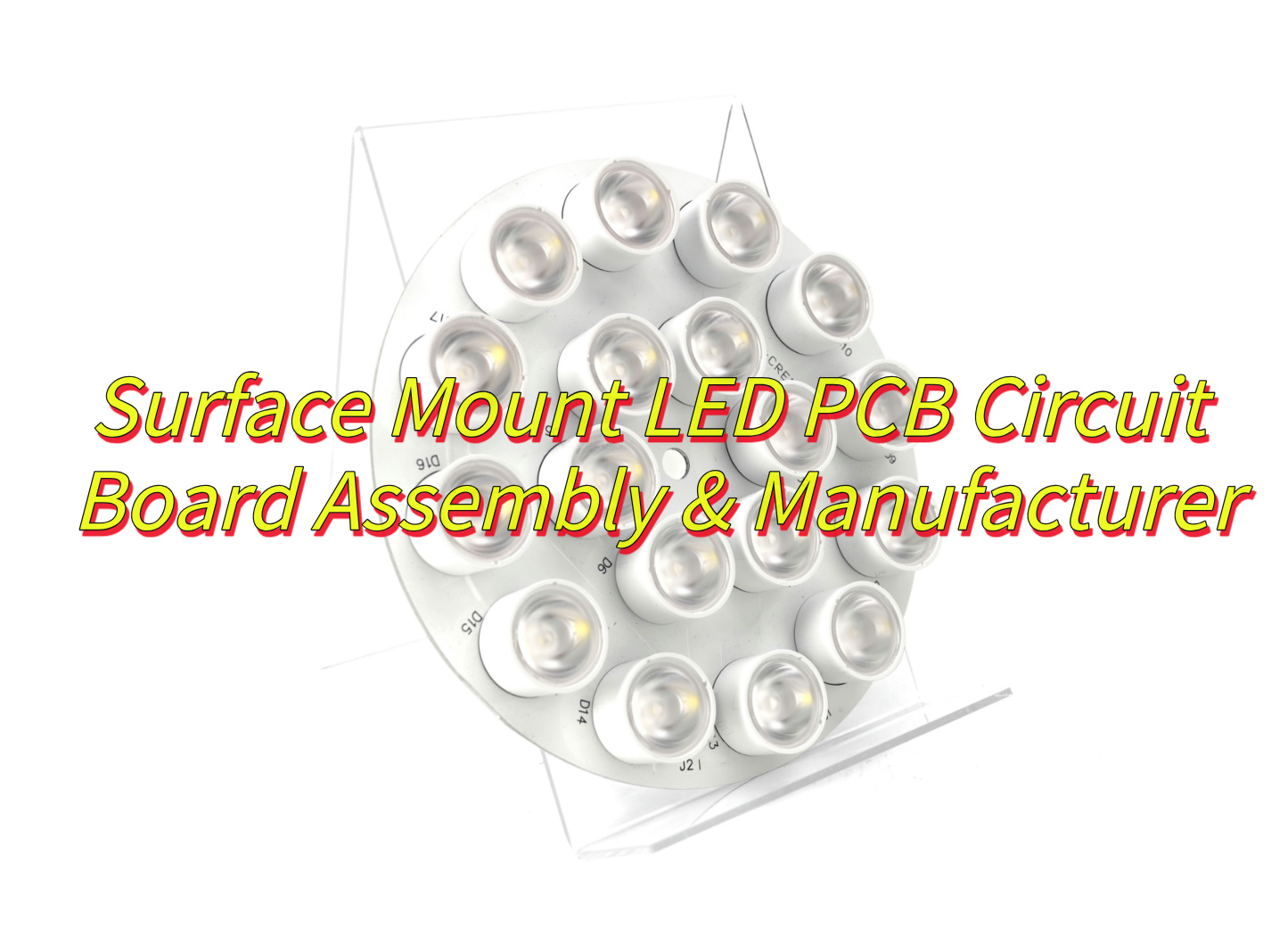
What is a surface mount LED PCB and why is it pivotal in modern electronics? This guide explores its benefits, assembly processes, manufacturer selection, quality control, and weatherproofing for optimized performance and durability.
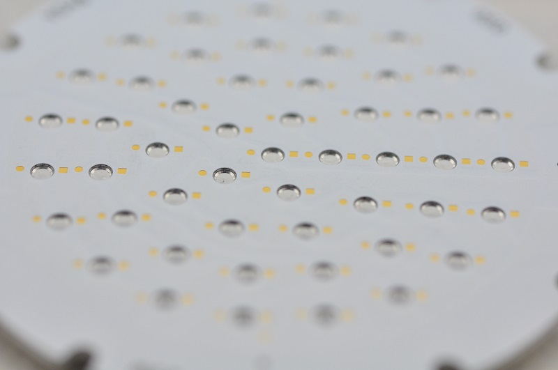
EBest Circuit (Best Technology) excels in surface mount LED PCB circuit board assembly, combining precision engineering with rapid production to meet diverse industrial demands. Our SMT assembly lines feature high-speed pick-and-place machines (30,000+ CPH) and closed-loop reflow ovens, ensuring ±30μm placement accuracy for complex layouts like 5050 RGB LEDs and 0.5mm pitch components. Advanced AOI (Automated Optical Inspection) and X-ray systems detect solder voids or misalignments, achieving >99.8% first-pass yield. Leveraging vertical integration, we source premium materials (e.g., 2W/m·K aluminum cores, SAC305 solder paste) in-house, eliminating delays. Our optimized supply chain and 24 hours rapid prototyping for urgent orders, backed by flexible capacity for urgent orders. Thermal simulations and rigorous testing (1,000-hour humidity/thermal cycling) guarantee 85°C stable operation for 15W+ LED arrays. Feel free to contact us today: sales@bestpcbs.com.
What Is A Surface Mount LED PCB?
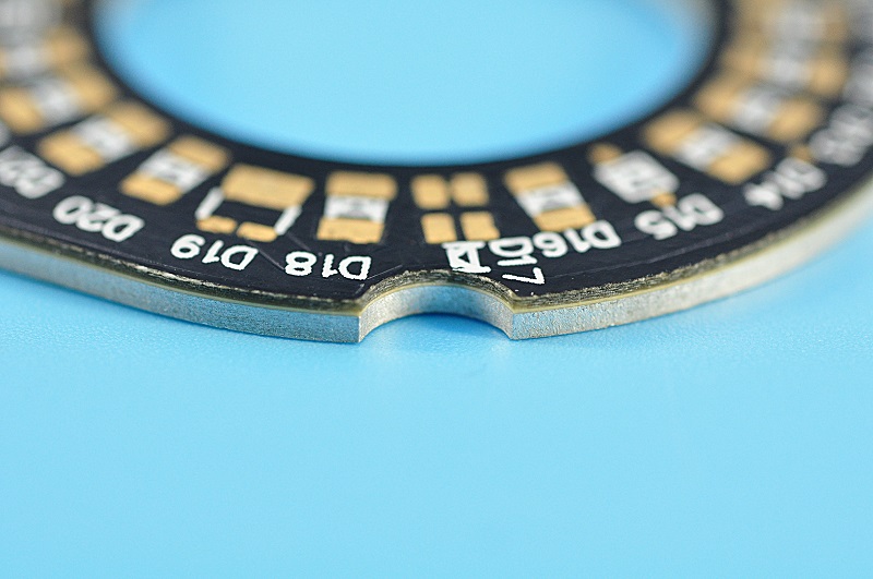
A surface mount LED PCB refers to a printed circuit board specifically designed to integrate surface-mount technology (SMT) for mounting LEDs directly onto its surface, eliminating the need for through-hole components. These PCBs utilize automated assembly processes to place miniature LED chips (e.g., 1206 or 0805 packages) onto solder pads, enabling high-density layouts, improved thermal management (via materials like FR4 or aluminum-core substrates), and compact designs ideal for applications such as backlighting, automotive lighting, or wearable electronics. A specialized variant, surface mount LED that exits through the PCB, features LEDs partially embedded into the board with their emission surfaces protruding through pre-milled openings, combining SMT efficiency with directional light control for indicators or panel-mounted displays. This design ensures mechanical stability, enhanced heat dissipation, and IP-rated durability in demanding environments.
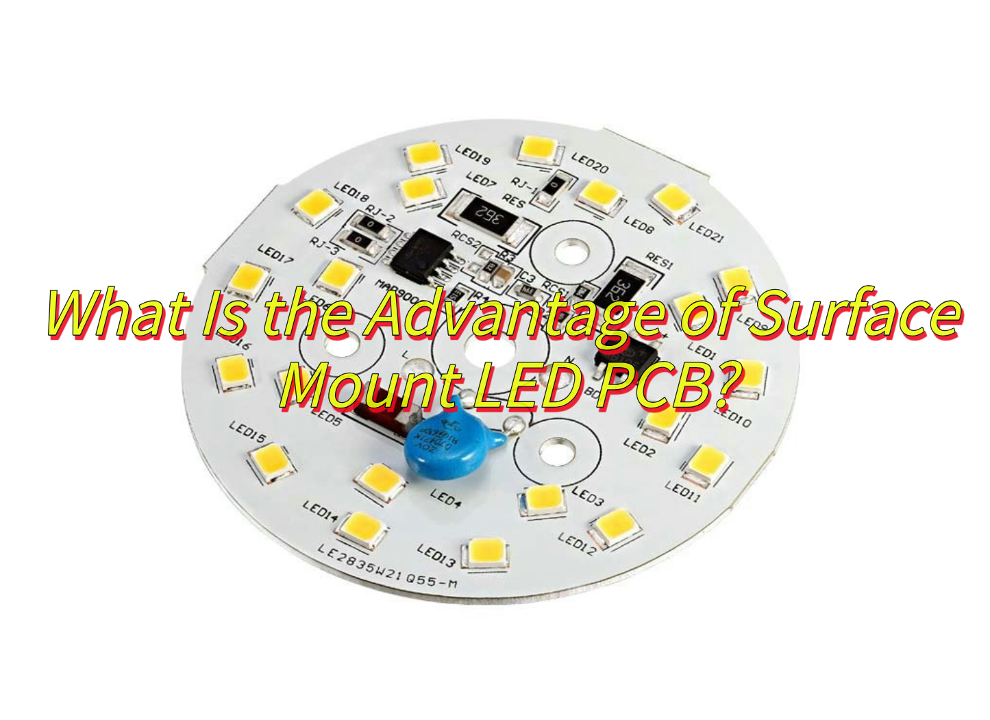
What Is the Advantage of Surface Mount LED PCB?
Surface Mount LED PCB (Printed Circuit Board) technology offers multiple benefits that enhance performance, efficiency, and applicability in modern electronics. Below is a detailed breakdown of its advantages:
Compact Design and High-Density Integration
Space Efficiency: Surface Mount LED PCBs enable smaller PCB footprints by eliminating the need for through-holes. This allows for denser component placement, critical for miniaturized devices like smartphones, wearables, and automotive interior lighting.
Lightweight Construction: Reduced material usage and smaller PCB dimensions lower the overall weight of electronic products, improving portability and energy efficiency.
Enhanced Electrical Performance
Improved Signal Integrity: Shorter signal paths and reduced parasitic inductance/capacitance minimize signal loss and electromagnetic interference (EMI), ensuring stable operation at high frequencies (up to 3GHz).
Thermal Management: Efficient heat dissipation through PCB layers prolongs LED lifespan, even under prolonged usage in applications like outdoor displays or industrial lighting.
Cost-Effective Manufacturing
Automated Assembly: Compatibility with SMT (Surface Mount Technology) production lines reduces labor costs and accelerates mass production.
Material Savings: Smaller PCBs and fewer drilling requirements lower raw material consumption, while advanced surface finishes (e.g., OSP, ENIG) balance cost and durability.
Durability and Environmental Resistance
Robust Construction: Surface Mount LEDs withstand vibrations and mechanical stress better than through-hole counterparts, making them ideal for automotive, aerospace, and harsh industrial environments.
Weatherproof Options: Specialized coatings and conformal layers protect PCBs from moisture, dust, and extreme temperatures, enabling outdoor use in LED streetlights or marine applications.
Design Flexibility and Aesthetic Appeal
Slim Profiles: Ultra-thin PCBs allow for sleek product designs, such as edge-lit TVs or flexible LED strips.
Uniform Lighting: Advanced SMD (Surface Mount Device) LEDs ensure consistent brightness and color mixing, critical for high-resolution displays and architectural lighting.
Energy Efficiency and Sustainability
Low Power Consumption: Surface Mount LEDs operate at lower voltages and currents compared to traditional LEDs, reducing energy costs.
RoHS Compliance: Lead-free manufacturing processes align with global environmental regulations, minimizing ecological impact.
Versatility in Applications
Consumer Electronics: Backlighting for LCDs, keypads, and appliances.
Extended Lifespan: High-quality surface finishes and thermal management extend PCB operational life to over 100,000 hours for LEDs.
What Is the Difference Between Surface Mount and Through-Hole LED PCB?
Surface Mount (SMT) and Through-Hole (THT) LED PCBs represent two distinct assembly technologies, each with unique attributes tailored to specific applications. Below is a structured comparison highlighting their differences:
Assembly Process Surface Mount LED PCB:
LEDs are mounted directly onto the PCB surface using solder paste and automated pick-and-place machines.
Reflow soldering melts the solder, creating permanent electrical and mechanical connections.
Ideal for high-volume production due to speed and precision.
Through-Hole LED PCB:
LEDs are inserted into pre-drilled holes on the PCB, and leads are soldered manually or via wave soldering on the opposite side.
Labor-intensive and slower, limiting scalability.
Space Utilization Surface Mount:
Enables compact designs by eliminating hole drilling, freeing up space for additional components.
Supports multi-layer PCBs and high-density layouts.
Through-Hole:
Requires dedicated holes for each LED, increasing PCB size and limiting component density.
Electrical Performance Surface Mount:
Shorter signal paths reduce inductance and resistance, improving high-frequency performance (e.g., in RF applications).
Better suited for high-speed data transmission and precision circuits.
Through-Hole:
Longer leads introduce parasitic capacitance, potentially degrading signal integrity at high frequencies.
Thermal and Mechanical Stability Surface Mount:
LEDs are prone to thermal stress during soldering but perform well under normal operating conditions.
Less durable in high-vibration environments compared to through-hole alternatives.
Through-Hole:
Stronger mechanical bonds due to leads passing through the PCB, offering superior resistance to shock and vibration.
Better for applications like automotive controls or industrial equipment.
Cost and Scalability Surface Mount:
Lower per-unit costs at scale due to automation.
Initial setup (e.g., stencils, reflow ovens) requires investment but pays off in mass production.
Through-Hole:
Higher labor costs and slower throughput increase expenses, especially for complex boards.
Repair and Prototyping Surface Mount:
Difficult to repair without specialized tools (e.g., hot air rework stations).
Prototyping may require stencils or skilled technicians.
Through-Hole:
Easier to replace components manually, favoring prototyping and low-volume runs.
Aesthetic and Design Flexibility Surface Mount:
Allows for sleek, low-profile designs (e.g., ultra-thin TV backlighting).
Uniform light emission due to tight component spacing.
Through-Hole:
LEDs extend above the PCB, limiting design aesthetics but enabling angled or adjustable lighting.
Typical Applications Surface Mount:
Consumer electronics (smartphones, laptops), automotive dashboards, and high-resolution displays.
Through-Hole:
Industrial controls, prototyping boards, and devices requiring ruggedness over compactness.
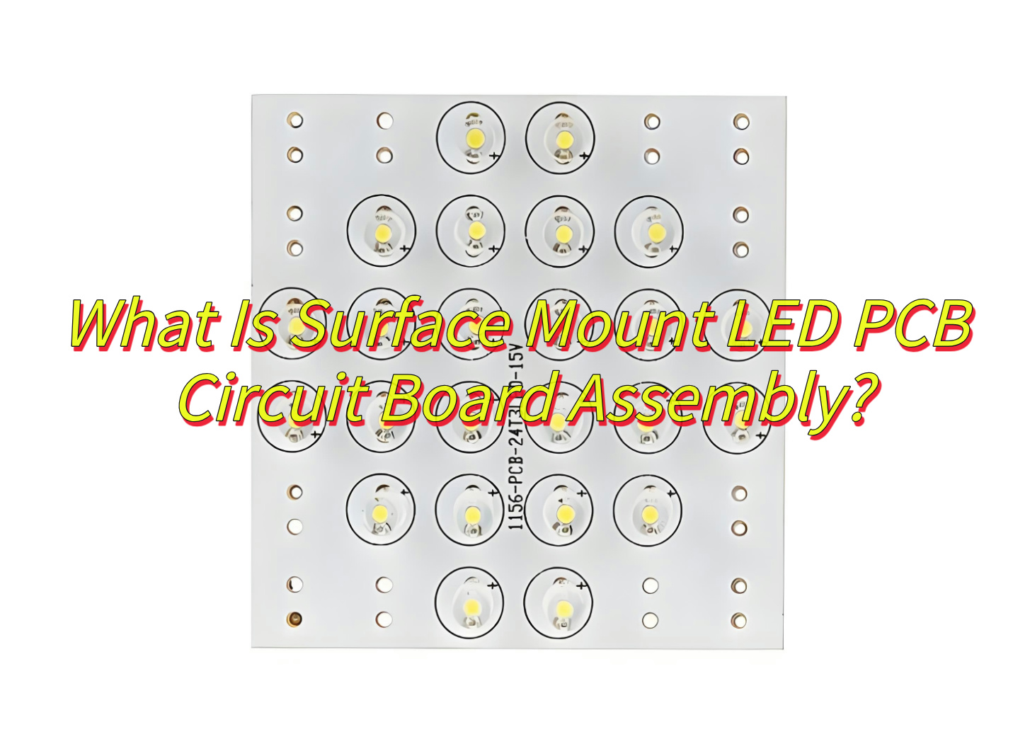
What Is Surface Mount LED PCB Circuit Board Assembly?
A surface mount LED PCB circuit board assembly refers to the process of attaching surface-mount device (SMD) LEDs onto a printed circuit board using automated surface-mount technology (SMT), where components are directly placed and soldered onto predefined solder pads without requiring drilled holes. This method employs solder paste application, precision placement via pick-and-place machines, and reflow soldering to secure miniature LEDs (e.g., 1206 or 0805 packages) onto the PCB surface, enabling high-density layouts and compact designs. Specialized configurations may include surface-mount LEDs that exit through the PCB, where the light-emitting portion protrudes via milled openings for directional applications like indicators or panel displays. The assembly ensures efficient thermal management through conductive substrates like aluminum-core PCBs and supports scalable, high-volume production for applications ranging from consumer electronics to automotive lighting.
What Steps Are Required For 15 Watt Surface Mount PCB Disc RGB LED Assembly?
Assembling a 15-watt surface mount PCB disc RGB LED involves precision engineering to ensure thermal management, electrical performance, and color accuracy. Below is a structured breakdown of the process:
1. PCB Preparation
Clean the PCB surface to remove contaminants (e.g., flux residue, dust) using isopropyl alcohol and lint-free wipes.
Inspect solder pads for oxidation or damage; repair or replace the PCB if issues are detected.
Apply a thin layer of thermal interface material (TIM) if the LED requires direct contact with a heat sink.
2. Component Placement
Use a vacuum pick-and-place machine to position the 15W RGB LED disc accurately on the PCB, aligning its pads with the solder paste.
Ensure polarity alignment (e.g., anode/cathode markers) to prevent electrical failures.
Place supporting components (e.g., resistors, capacitors, PWM controllers) nearby to minimize trace lengths.
3. Soldering Process
For mass production: Pass the PCB through a reflow oven with a temperature profile tailored to the solder paste’s specifications (e.g., 245°C peak for lead-free alloys).
For prototyping: Use a hot air rework station with a nozzle sized to the LED disc to avoid overheating adjacent components.
Avoid excessive heat exposure to prevent LED degradation or delamination of the PCB substrate.
4. Thermal Management Integration
Attach the LED disc to a metal-core PCB (MCPCB) or aluminum heat sink using thermal adhesive or screws, ensuring full contact.
Verify thermal conductivity by measuring the temperature rise during operation (target: below 85°C at maximum load).
5. Electrical Connection and Wiring
Solder fine-gauge wires (e.g., 24 AWG) to the LED’s anode/cathode pads and RGB channels, using a microscope for precision.
Insulate connections with heat-shrink tubing or conformal coating to prevent short circuits.
For RGB control, connect the LED to a microcontroller or driver IC capable of PWM signal modulation.
6. Testing and Calibration
Perform initial optical testing using an integrating sphere to measure luminous flux, color temperature, and CRI (Color Rendering Index).
Calibrate the LED’s RGB channels using software to achieve accurate color mixing (e.g., 16.7 million color options).
Conduct thermal cycling tests (-20°C to 85°C) to validate long-term reliability under temperature fluctuations.
7. Quality Assurance
Conduct visual inspections for solder joint integrity, component alignment, and signs of overheating.
Test electrical continuity across all connections using a multimeter.
Run a 24-hour burn-in test at 100% load to identify early-life failures.
8. Final Assembly and Packaging
Secure the PCB assembly into its housing (e.g., waterproof enclosure for outdoor applications).
Label the product with power ratings, safety certifications, and part numbers.
How to Select A Reliable Surface Mount LED PCB Manufacturer?
Choosing a reliable surface mount LED PCB manufacturer requires evaluating technical expertise, quality control, and industry reputation. Below is a structured guide to assist in the selection process:
Certifications and Standards Compliance
Verify certifications such as ISO 9001 (Quality Management), ISO 14001 (Environmental Management), and UL (Safety Standards).
Check for compliance with RoHS (Restriction of Hazardous Substances) and REACH regulations if targeting European markets.
Inquire about minimum order quantities (MOQs) and lead times for prototypes versus mass production.
Confirm capability to handle high-power LEDs (e.g., 15W RGB discs) and specialized PCB materials (e.g., aluminum-backed MCPCBs).
Quality Control Measures
Request details on testing protocols:
In-Circuit Testing (ICT) for electrical functionality.
X-ray Inspection for solder joint integrity in hidden layers.
Thermal Cycling Tests to simulate long-term operational stress.
Review defect rates (e.g., <0.1% return rate) and warranty policies.
Material Sourcing and Traceability
Ensure use of high-quality substrates (e.g., FR-4, Rogers 4003C) and LED components from reputable suppliers (e.g., Cree, Osram).
Confirm lot traceability for raw materials to enable root-cause analysis in case of failures.
Design for Manufacturability (DFM) Support
Evaluate whether the manufacturer offers DFM feedback to optimize PCB layouts for automated assembly.
Check for compatibility with common design software (e.g., Altium, Eagle) and file formats (Gerber, ODB++).
Customer References and Case Studies
Request references from clients in similar industries (e.g., automotive lighting, consumer electronics).
Review case studies demonstrating expertise in complex projects (e.g., weatherproof LED boards, high-lumen RGB assemblies).
Supply Chain Resilience
Inquire about contingency plans for material shortages or geopolitical risks.
Confirm lead time reliability during peak seasons (e.g., holiday orders for LED lighting products).
Ethical and Sustainability Practices
Audit labor practices (e.g., fair wages, safe working conditions) if corporate social responsibility is a priority.
Assess recycling programs for scrap PCBs and hazardous waste management.
Pricing and Payment Terms
Compare quotes across manufacturers, but prioritize value over cost alone.
Negotiate flexible payment terms (e.g., 30% deposit, 70% upon shipment) for large orders.
Communication and Cultural Fit
Gauge responsiveness via email/phone during initial inquiries.
Confirm project managers speak fluent English (or your preferred language) to avoid miscommunication.
How to Control Quality in Surface Mount LED PCB Manufacturing?
Ensuring robust quality in Surface Mount LED PCB manufacturing requires a multi-layered approach combining advanced technology, rigorous testing, and process discipline. Below is a structured guide to achieving consistent reliability:
Incoming Material Inspection
Substrate Verification: Check PCB laminates (e.g., FR-4, aluminum-backed MCPCB) for dielectric thickness, copper plating uniformity, and impurities using X-ray fluorescence (XRF) analyzers.
Component Authentication: Validate LEDs, resistors, and capacitors against datasheets using automated optical inspection (AOI) and electrical parameter testing (e.g., forward voltage, luminous flux).
Design for Manufacturability (DFM) Review
Conduct cross-functional reviews to identify potential assembly risks (e.g., insufficient solder pad spacing, inadequate thermal vias).
Use design software tools (e.g., Valor NPI) to simulate solder paste deposition and component placement accuracy.
Solder Paste Inspection (SPI)
Measure solder paste volume, height, and alignment pre-reflow using 3D SPI machines to prevent defects like solder bridges or insufficient joints.
Adjust stencil thickness (e.g., 0.1mm for fine-pitch LEDs) based on real-time data.
Automated Optical Inspection (AOI)
Post-reflow AOI systems detect component misalignment, tombstoning, or polarity reversals using multi-angle cameras and machine learning algorithms.
Calibrate systems weekly to maintain accuracy in detecting 0201/01005-sized components.
In-Circuit Testing (ICT)
Test electrical continuity, resistance, and LED functionality using bed-of-nails fixtures or flying probe testers.
Include boundary-scan tests for complex boards with BGA components.
X-ray Inspection for Hidden Defects
Use 2D/3D X-ray systems to inspect solder joints under BGAs, QFNs, and LED discs for voids, cold joints, or insufficient wetting.
Target <5% voiding in high-power LED thermal pads.
Thermal Management Validation
Simulate operating conditions with thermal chambers to verify LED junction temperatures remain below manufacturer specifications (e.g., <120°C for 3W LEDs).
Validate heat sink/PCB interface resistance using infrared thermography.
Environmental and Reliability Testing
Thermal Cycling: Expose PCBs to -40°C to 125°C cycles (1,000+ times) to assess solder joint durability.
Humidity Testing: Subject assemblies to 85°C/85% RH conditions for 168 hours to detect popcorning in moisture-sensitive components.
Vibration Testing: Shake PCBs per MIL-STD-202 standards to ensure mechanical robustness.
Color and Optical Performance Testing
For RGB/white LEDs, use integrating spheres to measure:
Luminous Flux: Ensure consistency within ±5% of specifications.
Color Temperature: Maintain Δuv < 0.005 for critical applications.
CRI (Color Rendering Index): Verify ≥90 for architectural lighting.
Statistical Process Control (SPC)
Monitor key parameters (e.g., solder paste volume, reflow oven temperature) in real-time using SPC charts.
Set control limits (e.g., ±1.5σ) to trigger alerts for out-of-spec conditions.
First Article Inspection (FAI)
Validate the first production batch against engineering drawings, including:
How Does Weatherproof Surface Mount PCB LED Manufacturing Ensure Durability?
Weatherproof Surface Mount PCB LED manufacturing requires specialized processes to withstand harsh environmental conditions such as moisture, UV exposure, temperature extremes, and mechanical stress. Below is a detailed breakdown of how durability is engineered into these products:
Material Selection for Resistance
PCB Substrates: Use high TG (glass transition temperature) FR-4 laminates (TG ≥ 170°C) or ceramic-filled polymers to resist warping and delamination in high-humidity or thermal cycling environments.
Solder Masks: Apply LPI solder masks with UV inhibitors to prevent cracking under prolonged sunlight exposure.
LED Encapsulants: Utilize silicone or epoxy resins with high moisture resistance (e.g., IP68-rated potting compounds) to protect LED chips from corrosion.
Design for Environmental Robustness
Conformal Coating: Spray-apply polyurethane to PCBs to create a moisture barrier while maintaining thermal conductivity.
Sealed Enclosures: Integrate gaskets (e.g., silicone, EPDM rubber) and ventilation membranes (e.g., Gore-Tex) into housing designs to balance pressure equalization and water ingress prevention.
Component Spacing: Maintain ≥0.5mm gaps between LEDs and other components to prevent thermal expansion-induced solder joint fatigue.
Advanced Manufacturing Techniques
Selective Soldering: Apply solder only to critical joints (e.g., LED pads) to minimize thermal stress on heat-sensitive components.
Underfill Dispensing: Inject epoxy under BGA LED packages to reinforce solder joints against vibration and thermal shock.
Laser Direct Structuring (LDS): Create 3D antenna traces on PCB housing for wireless-enabled LED fixtures, ensuring signal integrity in wet environments.
Rigorous Environmental Testing
IP Rating Verification: Submerge assemblies in 1m-deep water for 30 minutes (IP67) or 90 minutes (IP68) to confirm waterproofing.
UV Aging Chambers: Expose PCBs to 1,000+ hours of UVA-340 lamps to simulate 5+ years of outdoor sunlight exposure.
Salt Spray Testing: Apply 5% NaCl mist for 96 hours to evaluate corrosion resistance in marine environments.
Thermal Management Innovations
Metal-Core PCBs (MCPCBs): Bond aluminum or copper substrates to PCBs for 10x faster heat dissipation than FR-4, preventing LED degradation.
Thermal Vias: Drill arrays of 0.3mm vias filled with conductive epoxy to channel heat to heat sinks.
Phase-Change Materials (PCMs): Integrate PCM layers between LEDs and PCBs to absorb thermal spikes during operation.
Mechanical Reinforcement
Edge Plating: Add 0.2mm copper plating to PCB edges to resist bending in flexible LED strips.
Staking Compounds: Secure tall components (e.g., connectors) with epoxy staking to prevent detachment under vibration.
Quality Control During Assembly
Dry Storage: Keep PCBs and components in nitrogen-filled cabinets (≤5% RH) to prevent moisture absorption before soldering.
Reflow Profile Optimization: Use ramp-to-spike reflow profiles to minimize thermal shock while achieving >85% solder joint fill.
Automated Defect Sorting (ADS): Deploy AI-powered AOI systems to detect micro-cracks invisible to the human eye.
Long-Term Reliability Monitoring
HALT Testing: Subject prototypes to accelerated life testing (e.g., -40°C to 125°C cycles at 5°C/min ramps) to identify failure modes.
Weibull Analysis: Predict failure rates over 10+ years using data from 1,000-hour life tests at 85°C/85% RH.
Conclusion
In summary, that’s all about surface mount LED PCB’s benefits, assembly processes, manufacturer selection, quality control, and weatherproofing for optimized performance and durability. If you have any issues with surface mount LED PCB, welcome to leave a message below this blog.
Why chooseLED aluminum base PCBfor industrial lights? Explore its thermal management, design optimization, and manufacturer selection to enhance LED performance and longevity.
EBest Circuit (Best Technology) delivers LED aluminum base PCB designed for demanding thermal and electrical performance. Our streamlined manufacturing process ensures rapid 5-day prototyping and 15-day lead times for small-to-medium batches, supported by a monthly production capacity exceeding 10,000 panels. Every board integrates 6061-T6 aluminum cores and UL-certified dielectric materials, validated through thermal cycling (-40°C to +125°C), X-ray inspections, and ANSYS-based simulations to guarantee <0.8°C/W thermal resistance and >100 MΩ insulation durability. We accommodate diverse designs—star-base layouts, mixed-layer configurations, and custom copper pours—with no minimum order quantity, ideal for prototyping and specialized LED applications. With ISO 9001 certifications and full RoHS compliance, we maintain transparent pricing for orders ranging from 10 to 10,000 units. Welcome to contact us today if you have any request for LED aluminum base PCB: sales@bestpcbs.com.
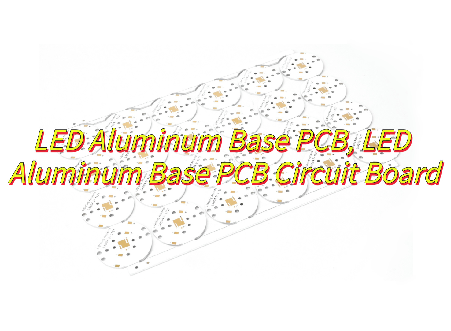
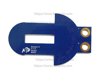
What Is A LED Aluminum Base PCB?
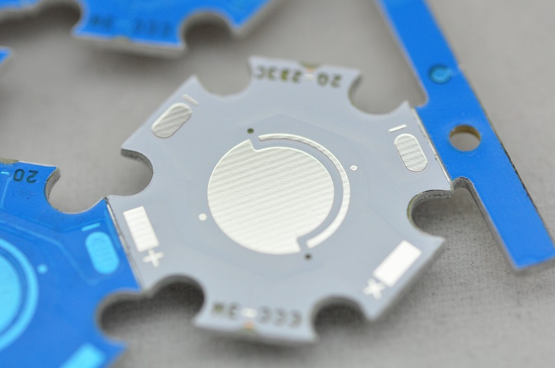
ALED aluminum base PCB is a specialized printed circuit board designed to support high-power light-emitting diodes (LEDs) by combining an aluminum substrate with a thermally conductive dielectric layer. The structure of LED aluminum base PCB is typically consists of three layers: a base plate made of aluminum alloy (e.g., 6061-T6) for heat dissipation, an insulating dielectric layer (often ceramic-filled polymer) to prevent electrical leakage, and a copper circuit layer for electrical connectivity. This design addresses the primary challenge of LED systems—heat accumulation—by efficiently transferring thermal energy away from the LEDs, maintaining optimal operating temperatures (typically -40°C to +150°C). Widely used in industrial lighting, automotive headlights, and commercial fixtures, these PCBs enhance LED longevity (often exceeding 50,000 hours) by reducing thermal stress on components like SMD 2835 LEDs. The aluminum substrate’s thermal conductivity (1.0–3.0 W/m·K) outperforms traditional materials like FR4, making it essential for applications requiring compact, durable layouts, such as 25W LED arrays or high-density automotive modules. Certifications like UL and IATF 16949 further validate their reliability in harsh environments, ensuring stable performance under vibration, humidity, and temperature fluctuations.
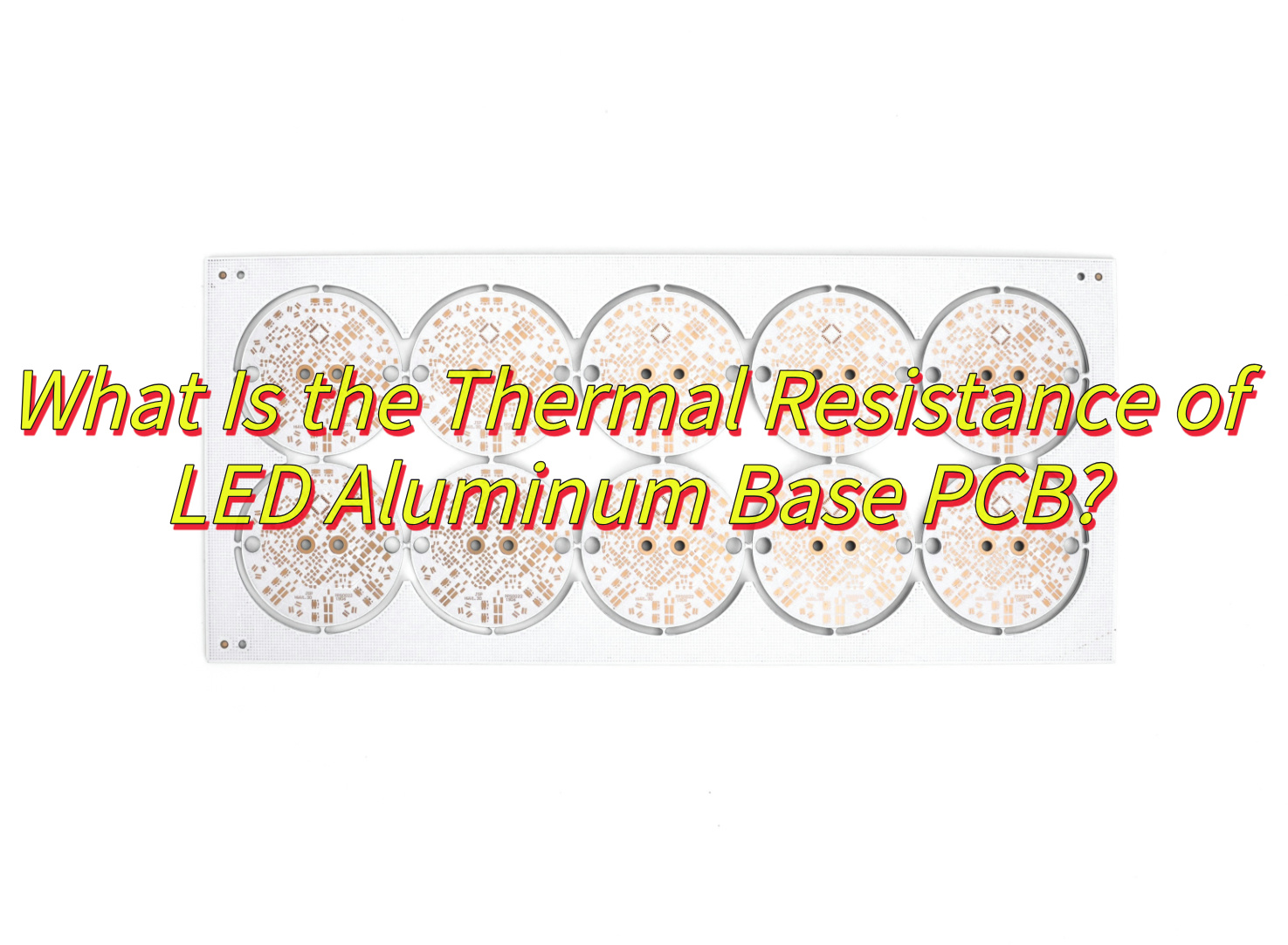
What Is the Thermal Resistance of LED Aluminum Base PCB?
The thermal conductivity of LED aluminum base PCB typically ranges between 1.0 W/m·K and 3.0 W/m·K, depending on material composition and structural design. While pure aluminum alloys (e.g., 6061-T6) exhibit high intrinsic thermal conductivity (~220 W/m·K), the overall PCB performance is constrained by the dielectric insulating layer between the copper circuit and aluminum substrate. This dielectric layer, often a ceramic-filled polymer (e.g., Al₂O₃ or AlN composites), dominates the thermal resistance due to its lower conductivity (0.5–3.0 W/m·K) compared to metallic components. For standard 1.5mm-thick aluminum PCBs, the thermal conductivity typically measures 2.0±0.1 W/m·K when using 0.1mm-thick dielectric layers with optimized ceramic particle dispersion. Advanced designs incorporating thermally conductive adhesives or ultrathin dielectric films (<0.08mm) can elevate conductivity to 2.5–3.0 W/m·K. In practical applications like 25W LED arrays, this conductivity ensures junction temperatures remain below 130°C under ambient conditions (25°C), as validated by thermal simulations and IEC 61215 testing protocols.
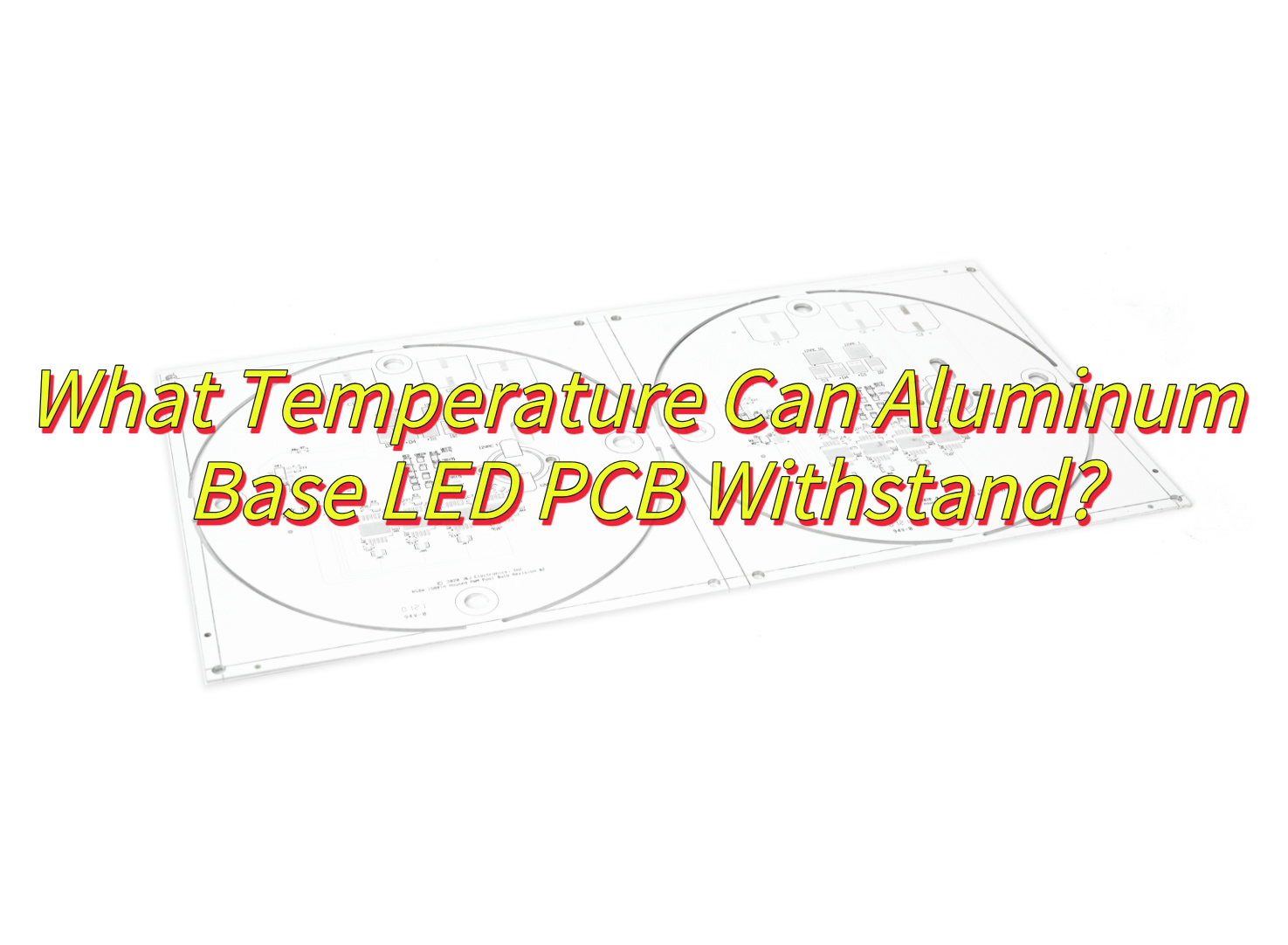
What Temperature Can Aluminum Base LED PCB Withstand?
Aluminum base LED PCB can typically withstand operating temperatures ranging from -40℃ to +150℃, with long-term reliability maintained below 120–130℃ under continuous thermal loads. The dielectric insulating layer between the copper circuit and aluminum substrate (e.g., ceramic-filled polymers) determines the upper temperature threshold, as prolonged exposure above 130℃ risks delamination or reduced adhesion. For short-term processes like soldering, these PCBs tolerate peak temperatures up to 260–300℃ for 5–10 seconds, aligning with reflow or wave soldering requirements. High-power LED applications (e.g., 25W automotive modules) often pair aluminum PCBs with heat sinks to stabilize junction temperatures below 130℃, while industrial lighting systems with H-grade insulation materials (rated for 180℃) may extend thermal limits under controlled conditions. Standard designs prioritize compliance with UL 94V-0 flammability ratings and IEC thermal cycling standards to ensure structural integrity across the rated temperature range.
How Do Aluminum Base PCBs Solve Overheating in 25W LED Star Base Designs?
Here is how LED aluminum base PCB solve overheating in 25w LED star base designs:
Direct Heat Pathway: Aluminum base PCBs provide a low-resistance thermal path by physically connecting LED chips to the aluminum substrate. In 25W LED star base designs, where multiple high-power LEDs are densely mounted, the aluminum layer acts as a heat spreader, rapidly transferring heat away from the LED junctions to prevent localized overheating.
Thermal Conductivity of Substrate: Aluminum’s inherent thermal conductivity (typically 1.0–2.5 W/m·K) enables efficient lateral heat distribution across the PCB surface. This reduces hotspots under high-power LEDs, ensuring uniform temperature management in compact star base geometries where airflow is limited.
Reduced Reliance on External Cooling: By dissipating heat at the source, aluminum base PCBs minimize dependence on passive or active cooling systems. In 25W applications, this design choice simplifies mechanical complexity, lowers costs, and improves reliability by eliminating failure-prone components like fans or heat sinks.
Material Compatibility with High-Power LEDs: The dielectric layer in aluminum PCBs, often formulated with ceramic-filled polymers, balances electrical insulation with thermal efficiency. This layer maintains a stable bond between the copper circuitry and aluminum base, ensuring reliable operation even under 25W thermal loads.
Structural Integration with Heat Sinks: Aluminum base PCBs are mechanically compatible with metallic star bases, enabling direct mounting to the housing. This integration eliminates thermal interface materials (TIMs) or additional fasteners, reducing interfacial thermal resistance and streamlining heat transfer to the ambient environment.
Enhanced Power Density Tolerance: For 25W LED arrays, the aluminum substrate’s ability to withstand elevated temperatures (typically up to 150°C) allows sustained operation without performance degradation. This thermal stability is critical for applications requiring consistent light output, such as automotive headlights or architectural fixtures.
Circuit Layout Optimization: Aluminum PCBs support thick copper traces (e.g., 2–3 oz. copper weight) to handle high currents while minimizing resistive heating. In star base designs, this ensures efficient power delivery to LEDs without adding excessive heat to the system.
Long-Term Reliability: By maintaining junction temperatures below critical thresholds (e.g., <120°C for most LEDs), aluminum base PCBs extend the operational lifespan of 25W LED systems. This reduces maintenance cycles and replacement costs, making them cost-effective for commercial and industrial use.
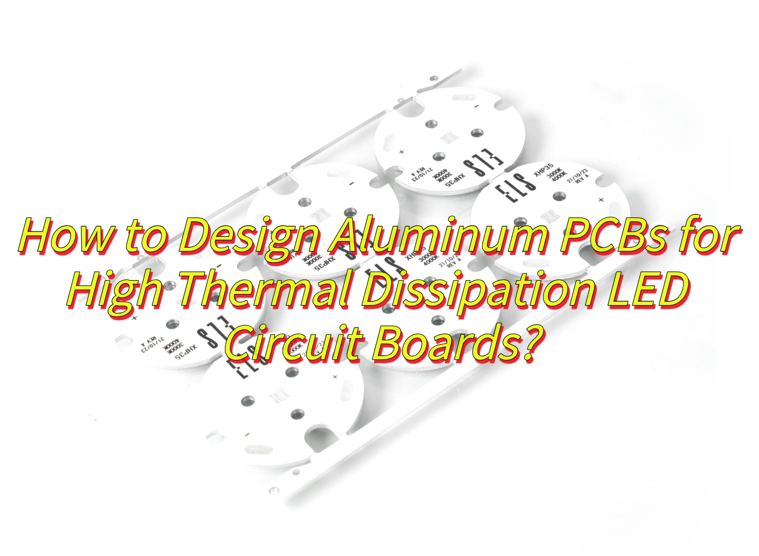
How to Design Aluminum PCBs for High Thermal Dissipation LED Circuit Boards?
This is how to design LED aluminum base PCB for high thermal dissipation :
Select High-Thermal-Conductivity Materials: Choose aluminum substrates with a thermal conductivity rating of at least 1.0–2.0 W/m·K to ensure efficient heat transfer from LEDs to the base. Pair with dielectric layers featuring ceramic-filled polymers (e.g., aluminum oxide or boron nitride) to balance electrical insulation and thermal performance.
Optimize Circuit Layer Copper Thickness: Use 2–3 oz. (70–105 µm) copper traces for the circuit layer to minimize resistive heating and improve current-carrying capacity. Thicker copper reduces Joule heating under high-power LED operation, directly lowering thermal load.
Maximize Direct Contact Area: Design the PCB layout to place high-power LEDs (e.g., 25W COB or SMD variants) directly over the aluminum base. Avoid large unpopulated regions to prevent heat pooling and ensure uniform heat spreading across the substrate.
Incorporate Thermal Vias Strategically: Add plated thermal vias beneath LED footprints to enhance vertical heat conduction to the aluminum layer. Use arrays of small-diameter vias (e.g., 0.3–0.5 mm) spaced 1–2 mm apart to minimize solder voids and maximize thermal pathways.
Use Solid Ground Planes: Dedicate the entire aluminum layer as a ground plane to reduce electromagnetic interference (EMI) and improve thermal dissipation. Ensure the ground plane is electrically isolated from the circuit layer via the dielectric material.
Design for Airflow or Convection: If external cooling is required, position components to allow unobstructed airflow over the aluminum base. Avoid placing tall components (e.g., connectors) near LEDs, as they may disrupt convective cooling.
Specify Low-Profile Components: Select surface-mount devices (SMDs) with minimal height to reduce thermal resistance between the PCB and any secondary heat sinks. Low-profile capacitors and resistors help maintain close contact with the aluminum substrate.
Apply Thermal Interface Materials (TIMs): Use high-performance TIMs (e.g., thermally conductive pads or phase-change materials) between the PCB and external heat sinks to fill microscopic air gaps. Aim for TIMs with thermal conductivity >3.0 W/m·K for optimal results.
Avoid Thermal Barriers in Layout: Route high-current traces away from LED thermal pads to prevent localized heating. Separate power traces from sensitive analog components to minimize crosstalk and thermal coupling.
Validate with Thermal Simulation: Use software tools (e.g., SolidWorks Flow Simulation) to model heat flow and identify hotspots before prototyping. Adjust component placement or copper weights based on simulation results to optimize dissipation.
Test Under Real-World Conditions: Subject prototypes to thermal cycling tests (e.g., -40°C to +125°C) and sustained power loads (e.g., 25W for 1,000+ hours) to validate long-term reliability. Monitor junction temperatures using infrared cameras or embedded sensors.
Collaborate with PCB Manufacturers Early: Engage fabricators during the design phase to ensure compatibility with manufacturing processes. For example, confirm that the dielectric layer thickness (typically 50–150 µm) meets both thermal and electrical insulation requirements.
How to Select A Good LED Aluminum Base PCB Circuit Board Manufacturer?
Verify Technical Expertise: Prioritize manufacturers with proven experience in LED aluminum PCB fabrication, including expertise in thermal management, dielectric material selection (e.g., ceramic-filled polymers), and compatibility with high-power LEDs (e.g., 25W COB or SMD types).
Check Quality Certifications: Ensure the manufacturer holds industry-standard certifications such as ISO 9001 (quality management), UL (safety), and RoHS (environmental compliance). Request samples or case studies demonstrating their ability to meet tight thermal conductivity tolerances (e.g., 1.0–2.5 W/m·K for aluminum substrates).
Assess Material Options: Confirm the manufacturer offers a range of aluminum alloys (e.g., 6061, 5052) and dielectric thicknesses (e.g., 50–150 µm) to balance thermal performance and electrical insulation. Inquire about specialized options like high-reflectivity white solder mask for LED applications.
Review Manufacturing Capabilities: Evaluate their equipment for precision drilling (e.g., laser drilling for thermal vias), plating (e.g., ENIG or immersion silver for solderability), and etching (to accommodate thick copper traces, typically 2–3 oz.). Ensure they can handle complex designs like star base geometries or multi-layer boards.
Request Thermal Testing Data: Ask for thermal impedance test results (e.g., junction-to-board thermal resistance) for their PCBs under simulated LED loads. Reputable manufacturers will provide data from accelerated life tests (e.g., 1,000+ hours at 25W).
Inspect Prototyping and Sample Process: Choose a manufacturer that offers low-cost prototyping (e.g., 3–5 boards) with quick turnaround (5–7 days). Evaluate sample quality for dimensional accuracy, via integrity, and dielectric adhesion.
Compare Pricing and MOQs: Obtain quotes for volume orders (e.g., 100–1,000 boards) and check for hidden costs (tooling, setup, or testing fees). Ensure their minimum order quantity (MOQ) aligns with your project scale (e.g., 50–100 boards for small batches).
Evaluate Customer Support: Gauge responsiveness to technical inquiries (e.g., stack-up design, impedance control) and willingness to provide design-for-manufacturability (DFM) feedback. A reliable manufacturer will flag issues like inadequate thermal via spacing or copper weight mismatches.
Check Lead Times and Scalability: Confirm they can meet your production deadlines (e.g., 2–3 weeks for standard orders) and scale capacity for reorders. Inquire about peak-season flexibility (e.g., Chinese New Year or holiday delays).
Audit Supply Chain Transparency: Ensure the manufacturer sources raw materials (aluminum, copper foil, dielectric) from reputable suppliers and provides traceability documentation. Avoid those with opaque or fragmented supply chains.
Review Warranty and Liability Terms: Look for manufacturers offering at least a 1-year warranty against defects like delamination, via fractures, or dielectric breakdown. Clarify liability for failures caused by thermal overstress or design flaws.
Seek Peer Recommendations: Consult industry forums (e.g., LED Professional, Electronics Weekly) or LinkedIn groups for unbiased reviews. Prioritize manufacturers referenced in multiple independent case studies (e.g., automotive lighting or horticultural LED projects).
How to Reduce LED Failure Rates with Aluminum Base PCB?
Here are some methods about how to reduce failure rates with LED aluminum base PCB:
Optimize Thermal Management: Use aluminum substrates with high thermal conductivity (1.0–2.5 W/m·K) and ultra-thin dielectric layers (50–80 µm) to minimize thermal resistance. This ensures efficient heat transfer from LED junctions to the aluminum base, keeping operating temperatures below 85°C to reduce light decay and thermal stress.
Improve Current Distribution: Design PCB traces with 2–3 oz. copper thickness to lower resistive losses. For high-power LEDs (e.g., 25W COB modules), adopt parallel or matrix wiring layouts to balance current density and prevent localized overheating.
Incorporate Thermal Vias: Add arrays of plated thermal vias (0.3–0.5 mm diameter, spaced 1–2 mm apart) beneath LED pads to enhance vertical heat conduction. This reduces thermal gradient between the LED junction and the aluminum base by up to 40%.
Select Robust Surface Finishes: Use ENIG (Electroless Nickel Immersion Gold) or immersion silver finishes to improve solder joint reliability. These finishes resist oxidation and corrosion, reducing failure risks in humid or high-temperature environments.
Avoid Mechanical Stress: Design PCBs with rounded corners and fillets to prevent stress concentrations during assembly or thermal cycling. For SMD LEDs, ensure solder pads match component dimensions to minimize shear forces.
Implement Proper Grounding: Dedicate the aluminum layer as a ground plane to reduce electromagnetic interference (EMI) and stabilize voltage fluctuations. This prevents electrical overstress (EOS), a common cause of LED degradation.
Use High-Quality Solder Pastes: Select no-clean solder pastes with low voiding rates (<10%) for reflow soldering. Poor solder joints increase thermal resistance and create hotspots, accelerating LED failure.
Conduct Accelerated Life Testing: Subject prototypes to 1,000+ hours of thermal cycling (-40°C to +125°C) and power cycling (25W load on/off every 2 hours). Identify weak points like dielectric cracks or via fractures before mass production.
Apply Conformal Coatings: For outdoor or harsh-environment applications, use UV-resistant conformal coatings (e.g., acrylic or silicone) to protect against moisture, dust, and chemicals. This extends PCB lifespan by 30–50% in corrosive conditions.
Monitor Real-World Performance: Deploy IoT-enabled sensors to track junction temperature, current, and light output during field trials. Use data analytics to predict failures and refine PCB designs iteratively.
Collaborate with LED Suppliers: Align PCB designs with LED datasheet recommendations for thermal pad dimensions, current limits, and derating curves. For example, match 25W LED thermal pads to PCB copper areas to ensure full heat dissipation.
Streamline Assembly Processes: Train operators on proper reflow profiles (e.g., 245°C peak for 60 seconds) and handling procedures to avoid mechanical damage. Automated optical inspection (AOI) can detect 95% of soldering defects pre-emptively.
Can Aluminum Based SMD 2835 LED PCBs Extend the Lifespan of Industrial Lights?
Yes, aluminum based SMD 2835 LED PCBs significantly extend the lifespan of industrial lights by combining efficient thermal management with robust structural support. The aluminum substrate acts as a heat sink, rapidly dissipating heat generated by high power SMD 2835 LEDs—a critical factor since every 10°C reduction in operating temperature can double LED lifespan. By maintaining junction temperatures below 85°C, these PCBs minimize thermal stress, light decay, and color shift over time. Additionally, the dielectric layer’s thermal conductivity (typically 1.0–2.5 W/m·K) ensures minimal thermal resistance, while the aluminum base’s rigidity resists vibration and mechanical stress common in industrial environments. This design also prevents solder joint fatigue and component degradation, reducing failure rates by up to 60% compared to standard FR4 boards. For applications like warehouse high-bays or factory floodlights, aluminum-based SMD 2835 LED PCBs deliver 50,000+ hours of reliable operation, lowering maintenance costs and downtime.
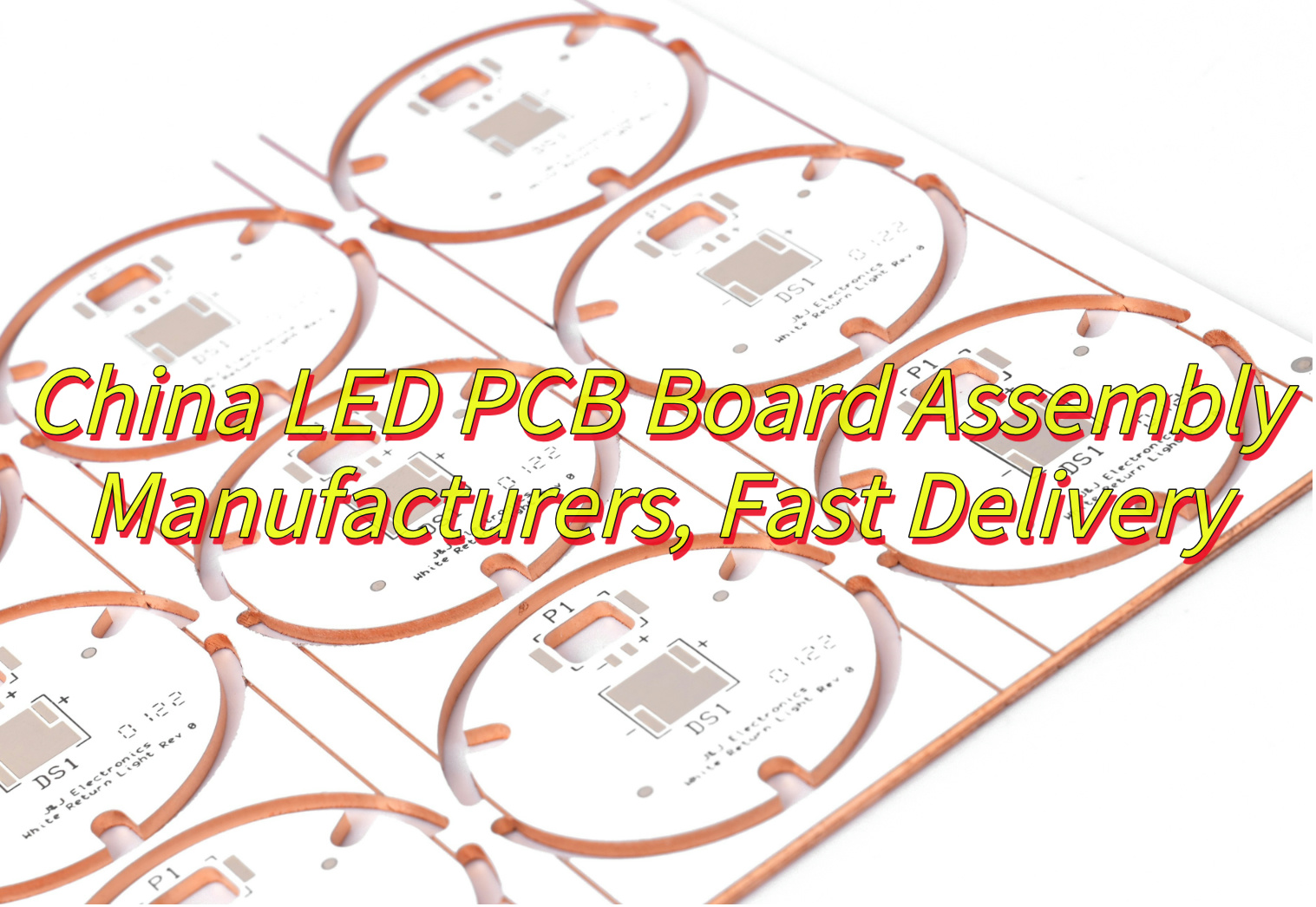
Why choose China LED PCB for your project? This guide examines cost-effective production methods, accelerated delivery protocols, and design customization feasibility within China LED PCB industry, addressing decision-making factors from pricing models to technical validation.
EBest Circuit (Best Technology) delivers China LED PCB manufacturing with 24-hour rapid prototyping supported by three dedicated quick-response lines. Our automated DFM analysis system processes design files within 90 minutes, identifying thermal management conflicts or impedance mismatches before manufacturing. Localized material warehouses maintain 48+ substrate variants, including aluminum-core boards (1.0–5.0mm thickness) and high-frequency Rogers 4350B, enabling immediate processing without procurement delays. Integrated AOI/X-RAY inspection stations achieve 99.98% first-pass yield, combining 10μm alignment checks with void detection (<5% IACS compliance). Production lines operate under IATF 16949 protocols, executing 4-hour batch changeovers for mixed LED configurations (SMD, COB, high-bay). Real-time logistics coordination through bonded ports ensures global shipments within 72 hours of final testing. Clients benefit from concurrent engineering support – our team resolves EMI/thermal issues during fabrication, eliminating post-production reworks. Continuous capacity scaling maintains 15% reserve throughput for urgent orders. Welcome to contact us: sales@bestpcbs.com.
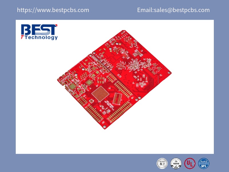
What Is China LED PCB?
A China LED PCB refers to a printed circuit board specifically designed and manufactured in China to support light-emitting diode (LED) applications. These boards are engineered to manage electrical connectivity, thermal dissipation, and mechanical stability for LED systems. Utilizing materials like FR-4, aluminum substrates, or ceramic composites, Chinese manufacturers optimize these PCBs for high-power LED lighting, automotive headlights, signage, and consumer electronics. Advanced production techniques include precision etching, solder mask application, and surface finishes such as HASL (Hot Air Solder Leveling) or ENIG (Electroless Nickel Immersion Gold) to ensure durability and efficient heat transfer. China’s LED PCB industry leverages scalable manufacturing infrastructure, cost-effective solutions, and compliance with international certifications like UL and RoHS, making it a global supplier for both standard and custom LED lighting solutions. Technical emphasis is placed on layer stacking, copper thickness optimization, and dielectric material selection to enhance luminous efficiency and longevity under varying operational conditions.
What Are Advantages of China LED PCB?
Advantages of China LED PCB:
Advanced Thermal Management Solutions – Chinese manufacturers employ aluminum-core substrates and ceramic composites to achieve superior heat dissipation, critical for maintaining LED performance in high-power applications like automotive lighting and industrial systems.
Cost-Effective Production Scaling – Leveraging mature industrial clusters and automated manufacturing processes, China delivers competitively priced LED PCBs without compromising quality, supporting global demand for consumer electronics and commercial displays.
Compliance with International Sustainability Standards - Adoption of RoHS-compliant materials and energy-efficient production methods aligns with global environmental regulations.
Customization for Smart Lighting Systems – Integrated circuit designs enable compatibility with ADB (Adaptive Driving Beam) modules, meeting evolving requirements for automotive and smart city infrastructure.
Rapid Technological Iteration Capabilities – Continuous R&D investments drive innovations in Micro LED miniaturization and ultra-fine pitch displays, positioning Chinese suppliers at the forefront of high-resolution visual solutions.
Robust Supply Chain Integration – Proximity to raw material suppliers and streamlined logistics networks ensure reliable component sourcing and reduced lead times, particularly for large-scale OEM/ODM projects.
Diverse Application Adaptability – From automotive headlights to virtual production studios, Chinese LED PCBs demonstrate versatility across industries, supported by modular designs and multi-layer stacking techniques.
Chinese manufacturers utilize aluminum-core substrates and ceramic composites to achieve thermal conductivity up to 8W/m·K, essential for high-power LED applications such as automotive headlights and industrial lighting systems. These materials prevent thermal degradation, ensuring LED longevity under continuous operation.
Precision Manufacturing Standards
Adherence to IPC-A-610F assembly guidelines and ISO 9001-certified processes guarantees consistent quality, with automated optical inspection (AOI) systems detecting defects at rates below 0.08%. Strict DFM (Design for Manufacturing) analysis preemptively resolves layout conflicts, reducing post-production revisions.
Cost-Efficient Production Scaling
Integrated industrial clusters in regions like Guangdong enable bulk procurement of raw materials, lowering unit costs by 20-35% compared to Western counterparts. Economies of scale support high-volume orders exceeding 500,000 units/month without compromising lead times.
Certification Compliance
Manufacturers hold IATF 16949 for automotive-grade modules and ISO 13485 for medical lighting, meeting stringent EU RoHS and REACH regulations for global market access. UL-recognized PCBs ensure safety compliance in North American markets.
R&D-Driven Innovation
Investment in Micro LED and COB (Chip-on-Board) technologies enables pixel pitches as fine as 0.4mm, catering to 4K commercial displays and virtual production studios. IoT-integrated designs support wireless dimming and color temperature adjustments for smart city infrastructure.
Agile Supply Chain Networks
Proximity to Shenzhen’s electronics hubs facilitates 24-hour component sourcing, with JIT (Just-in-Time) inventory systems reducing material shortages during peak demand. Dual sourcing strategies mitigate geopolitical trade risks for critical semiconductors.
Comprehensive Testing Protocols
End-to-end validation includes thermal cycling (-40°C to 150°C), 72-hour burn-in testing, and IP68 environmental stress screening to ensure reliability in harsh conditions. In-circuit testing (ICT) and flying probe systems verify electrical parameters with ±1% tolerance.
Customization Flexibility
Multi-layer stack-ups (up to 32 layers) and hybrid rigid-flex designs address space-constrained applications like wearable devices and aerospace instrumentation. Engineers optimize copper weights (2-12 oz) and solder mask textures for specific luminosity and EMI shielding requirements.
Sustainability Initiatives
Closed-loop water recycling systems and lead-free HASL surface finishes reduce ecological impact, with 98% material utilization rates in high-volume production. Solar-powered facilities align with carbon neutrality targets for eco-conscious clients.
Global Logistics Support
Dedicated customs brokerage teams expedite shipments to major ports, achieving 99.5% on-time delivery rates for EU and North American clients through bonded warehouse networks. Real-time SAP tracking integrates with client ERP systems for supply chain transparency.
How to Get a Cheap LED PCB Quote from China Manufacturers?
Strategies to how to get a cheap China LED PCB:
Utilize Online Quotation Tools – Submit detailed specifications through manufacturers’ web-based quote systems to receive instant pricing estimates.
Optimize PCB Design Specifications – Reduce costs by minimizing layer counts (4-6 layers for standard LED applications) and selecting FR-4 standard substrates unless high thermal demands require premium aluminum cores. Standardized panel sizes (18”×24”) maximize material utilization rates.
Request Volume Discount Structures – Manufacturers typically offer tiered pricing models, with unit costs decreasing 12-18% for orders exceeding 10,000 pieces. Confirm breakpoints for bulk pricing during initial negotiations.
Compare Supplier Quotes Strategically – Evaluate multiple manufacturers through B2B platforms like Made-in-China, cross-referencing unit prices against included services (DFM analysis, functional testing). Prioritize suppliers offering free engineering reviews.
Negotiate Component Sourcing Options – Choose partial turnkey services to leverage existing component inventories, reducing procurement lead times by 7-10 days. Confirm alternate part approvals for non-critical components to avoid sole-source markup.
Verify Certifications Early – Ensure manufacturers hold ISO 9001 and UL certifications for your target markets. Non-certified suppliers may appear cheaper initially but risk non-compliance penalties during customs clearance.
Clarify Logistics Responsibilities – Choose EXW (Ex-Works) terms to maintain control over shipping methods and customs brokerage. Consolidate shipments through freight forwarders for orders under 500kg to reduce per-unit logistics costs.
Request Prototyping Subsidies – Leading manufacturers often waive NRE (Non-Recurring Engineering) fees for prototype orders that convert to production batches within 60 days, lowering upfront development costs.
Monitor Material Market Trends – Time orders during copper foil price dips (typically Q2-Q3) to secure better rates. Manufacturers adjust quotes based on raw material indices updated weekly.
How to Shorten LED PCB Lead Time with Chinese Manufacturers?
Here is how to shorten the lead time of China LED PCB:
Streamline Order Processing and Documentation
Submit Complete Production Files Upfront: Provide Gerber files, BOM lists, and assembly drawings in one batch to minimize back-and-forth corrections. Clearly specify solder mask colors, surface finishes (e.g., HASL, ENIG), and other technical requirements.
Designate a Single Point of Contact: Avoid delays from multi-department coordination by assigning one person to liaise with the manufacturer via email or instant messaging tools for real-time updates.
Simplify Design and Reduce Process Complexity
Adopt Standardized Layouts: Prioritize single-sided or double-sided PCBs over multilayer designs (e.g., 6+ layers). If high-density interconnects are unavoidable, negotiate partial HDI production for critical sections only.
Avoid Specialty Materials/Processes: Use domestically sourced FR-4 substrates and standard finishes like HASL instead of immersion gold or OSP to accelerate material sourcing.
Partner with Agile Manufacturers
Evaluate Production Flexibility: Select factories with multiple automated lines (e.g., plating, etching) that can reprioritize orders during downtime. Request historical lead time data to gauge reliability.
Leverage Regional Supply Chains: Engage manufacturers in the Pearl River Delta (Shenzhen) or Yangtze River Delta for faster access to component suppliers and logistics hubs.
Negotiate Expedited Production and Shipping
Pay Premium for Rush Orders: Offer 10–20% extra to shorten key steps (e.g., drilling, plating). For example, a 7-day lead time might reduce to 4–5 days with dedicated line allocation.
Choose Air Freight: For orders under $5,000, negotiate with suppliers to cover partial air shipping costs (common for maintaining client relationships), cutting delivery from 15–20 days to 3–5 days.
Implement Parallel Production and Quality Checks
Overlap Inspection with Fabrication: Conduct flying probe testing and AOI checks during etching to catch defects early, avoiding post-production rework.
Early Third-Party Validation: Engage labs to test solderability and thermal stress after etching, enabling immediate process adjustments if issues arise.
Foster Long-Term Collaboration and Inventory Sharing
Sign Strategic Agreements: Lock in priority scheduling and inventory pooling via annual contracts. For example, pre-reserve capacity or stock common specs (e.g., 1.6mm FR-4) for urgent orders.
Co-Manage Safety Stock: Allow suppliers to pre-produce generic modules (e.g., driver boards) based on purchase history, enabling rapid fulfillment by only customizing LED sections per order.
Leverage Digital Tools for Efficiency
Integrate EDI Systems: Sync order, production, and shipping data with suppliers’ systems to eliminate manual entry delays. Auto-trigger production scheduling upon order confirmation.
Use Free DFM Software: Pre-screen designs with supplier-provided tools to fix issues like trace/space violations before formal submission, preventing production pauses.
Standardize Modules and Plan Alternatives
Design Modular Architectures: Separate LED arrays into scalable modules (e.g., driver + light engine). Stock standard drivers and produce custom light engines on demand, halving lead times.
Create Approved Alternate Parts Lists: Collaborate with suppliers to pre-qualify substitute components (e.g., equivalent LEDs, capacitors) to avoid delays from primary material shortages.
What’s the Real Cost of LED PCB Assembly from China vs Local Suppliers?
Here are price comparison between China LED PCB and Local LED PCB:
1. Direct Manufacturing Costs: China vs Local Suppliers
China: Labor-intensive steps (e.g., SMT placement, through-hole assembly) cost $0.003–$0.008 per pad for LED PCBs, depending on component density. A 100-piece order with 500 pads per board might total $150–$400 for assembly alone.
Local Suppliers (e.g., U.S./Europe): Same work ranges from $0.01–$0.02 per pad, tripling assembly costs to $500–$1,000 for the same 100-piece batch.
2. Material Sourcing and PCB Fabrication
China: Full-service factories bundle PCB fabrication and assembly. A 1.6mm thick, 2-layer FR-4 LED board with white solder mask costs $0.10–$0.30 per unit for 1,000+ pieces, including materials like 35µm copper and HASL finish.
Local Suppliers: PCB fabrication alone costs $0.50–$1.50 per unit for equivalent specs, excluding assembly. Material markups (e.g., Rogers/Isola substrates) add 20–50% if specified.
3. Logistics and Duties for China Sourcing
Shipping: Air freight adds 2–5 per board for express 3–5 day delivery, while sea freight reduces this to $0.30–$1.00 per unit but takes 3–4 weeks.
Tariffs: LED products under HTS code 9405.42 face 0–6% duties depending on regional trade agreements (e.g., U.S.-China Phase One deal).
4. Quality Control and Rework Risks
China: Mid-tier factories charge 2–5% of order value for AQL 2.5 inspection and functional testing. Failure rates for LED alignment or thermal issues average 1–3%, incurring $50–$150 per 1,000 boards in rework.
Local Suppliers: Typically include free AQL 1.0 inspection, with failure rates under 0.5%, minimizing rework costs but offset by higher upfront prices.
5. Tooling and NRE Fees
China: Stencil and fixture costs average $150–$300 one-time fees, amortized over 5,000+ units. Prototyping (5–10 boards) adds $200–$500 for engineering support.
Local Suppliers: NRE fees start at $500–$1,000, with prototyping priced at $300–$800 for equivalent services, reflecting higher labor rates.
6. Volume Discounts and Scalability
China: Price breaks occur at 500, 1,000, and 5,000 units. A 10,000-unit order might drop per-unit assembly costs to $0.002–$0.005 per pad vs. $0.01–$0.015 locally.
Local Suppliers: Discounts plateau at 1,000 units, with minimal per-unit reduction beyond 5,000 pieces, limiting scalability for high-volume projects.
7. Intellectual Property and Compliance Costs
China: NDA enforcement and IP audits add 1,000–3,000 annually. RoHS/REACH compliance certification costs $500–$1,000 per product family.
Local Suppliers: IP protection is often included in contracts, while compliance certifications average $200–$500, reflecting regional regulatory efficiency.
8. Total Cost of Ownership Comparison
China Example: 1,000 LED PCBAs (2-layer, SMT assembly, air freight) = $800(PCBs)+$2,500 (assembly) + $1,200(logistics/duties)+$100 (inspection) = $4,600 total.
Local Example: Same project = $1,500(PCBs)+$8,000 (assembly) + 0(logistics)+0 (inspection) = $9,500 total.
Savings: China sourcing offers 50–70% lower TCO for batches ≥500 units, despite added logistics and compliance overhead.
Do China LED PCB Suppliers Offer Free Gerber File Review Services?
Yes, many China LED PCB suppliers like EBest Circuit (Best Technology) offer free Gerber file review services to ensure designs meet manufacturability standards before production begins. Below is a detailed breakdown of how this service works, its limitations, and best practices for leveraging it effectively:
Purpose of Free Gerber Reviews
Design for Manufacturing (DFM) Checks: Suppliers analyze Gerber files to identify potential issues such as:
Inadequate trace/space clearances (e.g., <5mil for standard LED boards).
Missing solder mask layers or improper silkscreen placement.
Advanced thermal analysis or signal integrity simulations.
Full redesign assistance (e.g., routing adjustments, component placement).
Compliance testing (e.g., UL certification, RoHS documentation).
Turnaround Time and Process
Standard Timeline: 24–48 hours for most suppliers, depending on file complexity.
Expedited Options: Some factories offer 4–6 hour reviews for urgent orders (may charge 20–50 for priority handling).
Delivery Method: Results are shared via email or an online portal with annotated Gerber files highlighting issues.
Conditions for Free Access
Order Commitment: Free reviews are usually contingent on a confirmed quote or intent to place an order.
File Format Requirements: Accepted formats include Gerber RS-274X, ODB++, or IPC-2581. Legacy formats (e.g., Gerber X2) may require conversion fees.
Complexity Thresholds: Free reviews apply to standard LED PCBs (e.g., single/double-sided, through-hole components). HDI, flex, or metal-core boards often require paid engineering reviews (50–200).
How to Request a Review
Pre-Quote Submission: Attach Gerber files when requesting a quotation to trigger automatic DFM analysis.
Supplier Portals: Larger manufacturers (such as Best Technlogy) offer free online tools for instant DFM feedback.
Direct Engagement: Email files to sales engineers with a clear request: “Please conduct a free DFM review prior to formal quotation.”
Potential Pitfalls to Avoid
Automated-Only Checks: Ensure a human engineer verifies results, as purely automated tools may miss contextual issues (e.g., LED footprint alignment).
Language Barriers: Work with suppliers offering English-speaking engineering support to clarify design intent.
Alternatives to Free Reviews
Third-Party DFM Tools: Use free software like KiCad’s DRC or PCB Checker to self-audit files before submission.
Paid Engineering Support: For mission-critical projects, budget 50–200 for detailed reviews by specialists.
Negotiating Enhanced Support
Prototype Runs: Request a free “NPI (New Product Introduction) package” including 1–2 Gerber reviews with prototype orders.
Long-Term Agreements: Secure annual contracts with monthly DFM quotas (e.g., 10 free reviews/month) in exchange for volume commitments.
Can China LED PCB Manufacturers Meet My Custom Design Requirements?
Yes, China LED PCB manufacturers can meet custom design requirements, offering flexibility in specifications, materials, and production processes. Below is a detailed analysis of their capabilities, limitations, and best practices for collaborating effectively:
Design Customization Capabilities
Layer Count and Stack-Up: Capable of producing single-layer to 12+ layer boards, with options for blind/buried vias and controlled impedance for high-speed LED drivers.
Material Selection: Access to specialized substrates like aluminum-backed PCBs for thermal management, FR-4 for cost efficiency, and high-frequency materials (e.g., Rogers 4350B) for RF applications.
Surface Finishes: Offer HASL, ENIG, immersion tin, and OSP finishes to suit soldering requirements and environmental resistance.
Component Placement: Support for 01005 passives, QFNs, BGAs, and through-hole LEDs with automated optical inspection (AOI) for accuracy.
Specialized Processes for LED Applications
Thermal Vias and Copper Cores: Manufacturers routinely incorporate thermal vias (e.g., 0.2mm diameter, 1:1 aspect ratio) and copper-core layers to dissipate heat from high-power LEDs.
Optical Clearance: Precision routing to maintain 0.5mm+ clearance between LED pads and copper traces to prevent light bleed.
White Solder Mask: Standard offering for LED boards, with options for matte finishes to reduce glare in lighting applications.
Design Collaboration Workflow
DFM Reviews: Free analysis of Gerber files to flag issues like trace/space violations (e.g., <5mil for standard LED boards) or missing solder mask layers.
Engineering Support: Larger factories employ in-house engineers to suggest design optimizations, such as panelization strategies to reduce costs.
Prototyping: Rapid turnaround (24–72 hours) for 5–10 piece prototype batches using SMT lines dedicated to small orders.
Quality Control for Custom Designs
Electrical Testing: Flying probe testing (FPT) for prototypes and dedicated fixtures for high-volume runs, ensuring continuity and isolation resistance meet IPC-A-600 standards.
Thermal Cycling: Optional stress testing (-40°C to +125°C) for automotive or outdoor LED applications, typically costing 50–150 per batch.
Cross-Section Analysis: Destructive testing to validate plating thickness and layer adhesion, often included in NPI (New Product Introduction) packages.
Limitations and Risk Mitigation
Minimum Order Quantities (MOQs): Custom designs may require 50–100 piece MOQs due to setup costs for specialized tooling (e.g., stencils, fixtures).
Lead Time Extensions: Custom stack-ups or exotic materials (e.g., ceramic substrates) can add 3–5 days to lead times.
Language Barriers: Use suppliers with English-speaking engineers to clarify design intent during reviews.
Cost Considerations
NRE Fees: One-time charges for stencils (50–150) and fixtures (100–300), amortized over 1,000+ units.
Material Premiums: Aluminum-backed PCBs cost 20–40% more than FR-4, while Rogers 4350B adds 50–100% to material costs.
Volume Discounts: Per-unit costs drop 30–50% when scaling from 100 to 1,000 pieces, with further reductions at 5,000+ units.
How to Ensure Success with Custom Designs
Provide Detailed Specifications: Include thermal requirements, optical clearance rules, and mechanical constraints in the RFQ.
Request Sample Runs: Order 5–10 pieces for validation before full production, especially for rigid-flex or HDI designs.
Secure Intellectual Property: Use NDAs and watermark sensitive files during the quoting phase.
By aligning design complexity with supplier capabilities and proactively addressing potential risks, buyers can leverage China’s manufacturing ecosystem to produce high-quality, customized LED PCBs at competitive costs.
MCPCB manufacturer is the term every engineer and procurement manager is searching for when LED performance and heat dissipation matter. The growing demand for high-brightness lighting and power electronics has made MCPCBs the go-to option for many industries. From LED lighting and automotive to telecom and industrial applications, these boards serve as reliable heat spreaders and signal carriers. As the market grows, so does the need for professional suppliers who understand the challenges of thermal management and efficient layouts.
EBest Circuit (Best Technology) implements a high-efficiency order-solving process and implements a 2-3 weeks lead time policy from the top down. We are an honest business. We prefer to lose face instead of losing customers, and we prefer to lose interest instead of the market. You can always trust EBest Circuit (Best Technology) for the diverse specifications of MCPCB, high quality, customizable design solutions, small quantity manufacturing, quick turn-around, and professional after-sales support. Share your request with us at sales@bestpcbs.com.
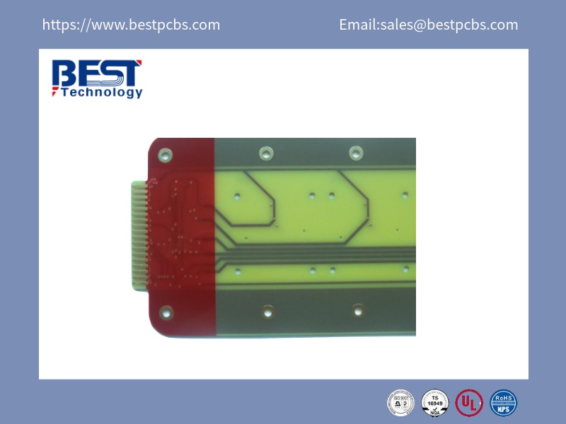
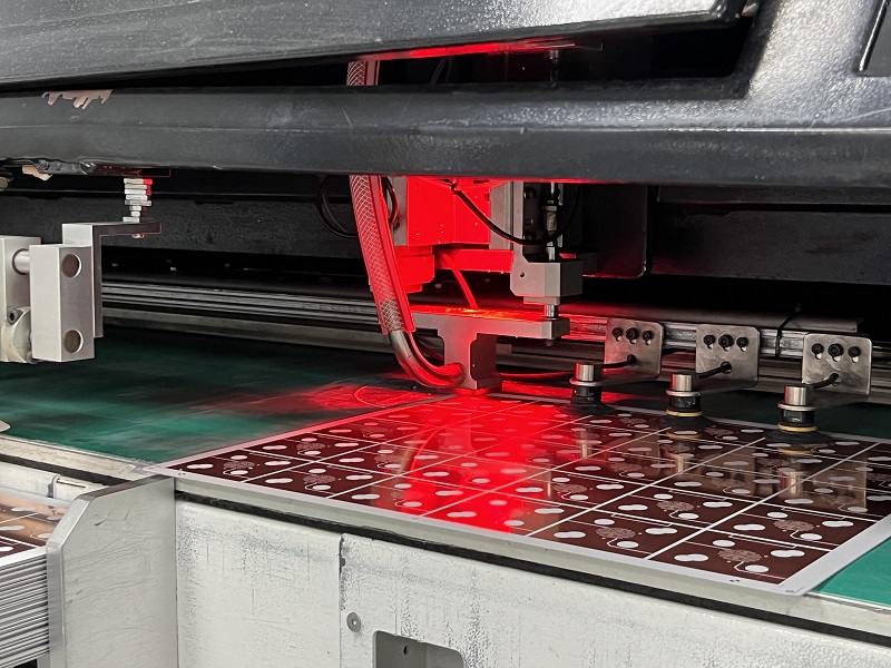
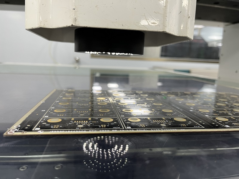
How is the MCPCB manufacturing process?
MCPCB manufacturer workflows vary based on product types, but for single-sided thermoelectric separation copper-based boards, the process is more refined and specialized. This kind of MCPCB is engineered to offer excellent thermal performance and reliability, especially in high-power LED and power module applications. To understand the build quality behind a reliable MCPCB, it’s important to look closely at how both the panel and the base board are made. From raw material preparation to surface finish and final testing, every step is monitored to ensure performance and consistency. Let’s walk through the real process behind these boards.
Panel Manufacturing Process:
Cutting: The raw material is cut to the required size.
Baking: Pre-baking removes internal moisture.
Circuit Imaging: Patterns are transferred using photoresist.
QC Inspection: Visual check for imaging defects.
Etching: Unwanted copper is etched off to reveal the circuit.
Etching QC: Visual, AOI (Automated Optical Inspection), and intermediate testing are done.
Laminating PP: Pure resin prepreg is added between layers.
Drilling/Target Hole: Drilling aligns layers and creates through-holes.
Milling Slots: Grooves and stand positions are machined.
Waiting for Lamination: Prepared for pressing with the base.
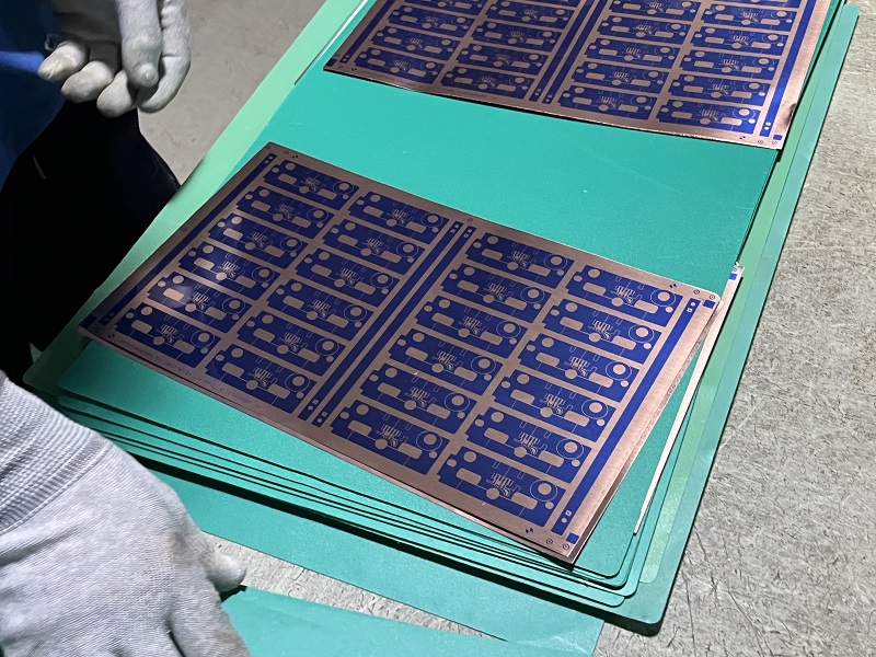
Substrate Manufacturing Process:
Cutting: Substrate base is trimmed.
High Temp Film Application: A protective high-temperature film is added unless already present.
Grinding: Surface is cleaned and prepared.
Circuit Tower Processing: Using dry or wet film, circuit elevations are formed.
Etching: Refines the copper features.
Pressing: The panel and substrate are laminated.
Stripping Film): Film is removed after bonding.
Target Hole Drilling: Ensures precise alignment.
Grinding Again: Ensures cleanliness.
Solder Mask: Includes resting, baking, exposure, and developing.
Solder Mask QC: Inspected for uniformity.
Silkscreen Text: Characters or labels are printed.
Baking Curing: Sets the ink and layers.
Surface Finish: Options include OSP, ENIG, ENEPIG, or lead-free HASL.
Shaping: Final machining with drilling, V-CUT, or routing.
Testing: Electrical tests ensure performance.
FQC/FQA: Final Quality Control & Final Quality Assurance.
Vacuum Packing: Boards are sealed to prevent moisture.
Warehousing & Shipping: Ready for delivery.
The MCPCB manufacturing process—especially for single-sided thermoelectric separation boards—is both detailed and deliberate. From panel preparation to surface treatment and precision testing, each step plays a role in heat management and structural durability. When choosing an MCPCB manufacturer, it’s not just about the end product but also about the reliability of the process behind it. A transparent and tightly controlled manufacturing workflow often reflects the quality and performance of the final board.
PCB Manufacturers in Mexico
Mexico has become a hotspot for reliable PCB manufacturing due to its geographic advantage and increasing electronics demand. Here are three noteworthy manufacturers:
JAV Electro: They offer quick-turn PCB prototyping and mid-volume production. Their local facility allows faster lead times and tight quality control.
Bittele Mexico: A branch of Bittele Electronics, they provide full PCB services including assembly and component sourcing.
PCBCart Mexico: Though based in China, PCBCart’s Mexican logistics support ensures rapid delivery and regional support for North American clients.
Mexico’s PCB sector is gaining traction thanks to responsive service and proximity to the U.S. electronics market.
MCPCB Manufacturers USA
The U.S. is home to many well-known MCPCB manufacturers offering high-reliability boards for LED, automotive, and aerospace applications.
Advanced Circuits: Located in Colorado, they provide MCPCBs with same-day prototyping and certification for aerospace and medical industries.
Rush PCB Inc.: This California-based company offers metal-core PCBs with excellent thermal design support and fast prototyping.
Bay Area Circuits: They specialize in custom thermal management boards and short production cycles for startups and innovators.
U.S. manufacturers prioritize precision and turnaround, making them dependable for time-critical and high-end projects.
LED MCPCB Manufacturers China
China leads the world in LED MCPCB production. Competitive pricing and scalable production define the market.
EBest Circuit (Best Technology) Co., Limited: Known for its rapid MCPCB prototyping, especially for aluminum LED applications.
Shenzhen JDB Technology: They focus on custom LED MCPCBs, offering high thermal conductivity and RoHS compliance.
Kinwong Electronic: One of the top 100 PCB companies in China, they provide large-scale LED MCPCB solutions.
If you need volume and cost-efficiency, China’s LED MCPCB makers deliver both, without compromising quality.
Projector MCPCB Manufacturer
MCPCBs used in projectors must offer strong thermal dissipation and precise alignment for consistent light output.
EBest Circuit (Best Technology): Our projector MCPCBs come with customized thickness and metal base options.
Thermaltronics: Specializes in heat-resistant MCPCBs for high-lumen projection systems.
Ventec International Group: While known for laminates, they partner with MCPCB producers to supply materials specific for projection use.
Projector MCPCB makers tailor their products for optical clarity and heat resistance, enhancing device life and performance.
Berquist MCPCB Manufacturers
Berquist materials are considered premium for thermal conductivity. Here are manufacturers known to work with or specialize in Berquist-based MCPCBs.
EBest Circuit (Best Technology) Co., Limited: EBest Circuit (Best Technology) uses Berquist substrates for top-tier thermal performance in LED and automotive MCPCBs. We offer standard and Berquist-based MCPCBs with 2-3 weeks lead time and ISO ISO9001, ISO13485, IATF16949, AS9100D, and UL certifications.
Amitron Corporation: Based in Illinois, Amitron specializes in thermal management PCBs and often uses Berquist laminates for industrial clients.
Manufacturers using Berquist base materials produce MCPCBs with exceptional heat transfer properties, ideal for high-load applications.
Why Should You Choose EBest Circuit (Best Technology) as Your MCPCB Manufacturer?
EBest Circuit (Best Technology) is not just a name. It’s a promise. Here’s why customers from over 40 countries choose us:
Full Customization – Whether you need a single-sided aluminum board, a complex multilayer MCPCB or a customized Aluminum PCB, we tailor the stackup to your project.
Experienced Team – With 18+ years in MCPCB production, we’ve tackled nearly every application type.
In-House Testing – Thermal imaging, impedance checks, and continuity testing are standard.
Material Options – We offer aluminum, copper, and even stainless steel bases, depending on your needs.
Rapid Prototyping – Get samples in days, not weeks. For specific lead time information, just feel free to get in touch with us at any time.
Global customer distribution – From Asia to the USA and across Europe, our market share continues to soar rapidly.
We understand what makes a board reliable under heat and current. EBest Circuit (Best Technology) never stops fostering professional talents. Most of our account managers, sales managers, procurement, and R&D engineers have the experience over 10 years. From the top down in EBest Circuit (Best Technology), we believe maintaining consistency in quality and service is the key to getting the trust of our potential and regular customers. We believe understanding the customer’s needs and tackling their problems helps establish a long-term relationship and create a win-win situation.
To put it simply, finding the right MCPCB manufacturer is about more than specs and cost. It’s about working with a team that listens, understands thermal design, and helps turn your idea into reality. Whether you’re looking for a led MCPCB manufacturer in India, MCPCB manufacturer in China, or a custom MCPCB solution, EBest Circuit (Best Technology) provides experience, flexibility, and speed. Our aluminum PCBs, projector MCPCBs, and Berquist-compatible builds are already powering devices worldwide. Get in touch with us at sales@bestpcbs.com for any questions or doubts.
High-TG PCB manufacturer EBest Circuit (Best Technology) knows the growing demand for high-temp, high-performance boards. As industries shift to powerful, heat-intensive electronics, reliable high-TG PCBs become crucial. Whether you need a few prototypes or large production, choosing the right partner matters. Let’s dive into how to choose the best supplier for your needs.
Established in 2006, EBest Circuit (Best Technology) has 18 years of expertise in creating high-TG PCB design, making high-TG PCB fabrication, and doing high-TG PCB assembly. As an R&D-driven factory, EBest Circuit (Best Technology) invites state-of-the-art facilities in our SMT factories in Vietnam and China. We implement the client-centric approach and deliver seamless high-TG PCB manufacturing service to our partners. EBest Circuit (Best Technology) implements stringent quality control measures, including design rule check (DRC), automated optical inspection (AOI), electrical testing (E-Test), X-ray inspection, and impedance control. All materials are RoHS-compliant and lead-free. For any high-TG PCB inquiries or technical issues, kindly send us an email to sales@bestpcbs.com.
What Is a High Tg PCB?
A High Tg PCB uses material that withstands much higher temperatures than standard FR4. Tg stands for Glass Transition Temperature. It marks the point where a material changes from solid and glassy to soft and rubbery. Standard FR4 PCBs have a Tg around 130–140°C. High Tg PCBs have a Tg higher than 170°C, offering better thermal stability and mechanical strength.
When the board’s temperature goes above its Tg, it may deform and lose performance. But a high Tg PCB stays stable. That’s why these boards are ideal for automotive electronics, LED lighting, industrial control, and high-power devices. They help your products last longer and work better under thermal stress.
In fact, many customers in the LED sector prefer high Tg FR4 over metal core PCBs for cost reasons, especially when the thermal conductivity demands are moderate.
At EBest Circuit (Best Technology), we commonly use SYL’s S1170 material for high-TG PCBs. Here’s a simple view of the FR4 Tg 170 datasheet you can refer to:
Item
Specification
Tg (DSC)
≥170°C
Decomposition Temp (Td)
>340°C
Thermal Conductivity
0.35 W/m·K
Flammability Rating
UL 94 V-0
CTI
≥300V
Water Absorption
<0.10%
Electrical Strength
≥40 kV/mm
This material shows excellent stability at high temperatures and good insulation properties. It’s highly recommended for multi-layer PCBs, fine-pitch SMT, and lead-free soldering processes.
Special notes:
SYL S1170 is also widely used in high-brightness LED projects.
It supports PCB structures with over 6 layers.
Need a detailed FR4 high TG datasheet? Contact EBest Circuit (Best Technology) anytime!
Who Manufactures High Temp PCB?
Many suppliers claim they can build high temp PCBs, but not everyone offers real high-TG expertise. Here’s a quick introduction to three trusted manufacturers:
EBest Circuit (Best Technology) Co., Ltd (China)
Specializes in high Tg PCB, ceramic PCB, metal core PCB, and flex PCB. We support low to high volume PCB fabrication with no MOQ. Focused on quick turn, high quality, and customized solutions.
Isola Group (USA)
A famous material supplier, Isola also partners with certified PCB manufacturers worldwide. Their FR406 and IS410 laminates are industry benchmarks for high-TG applications.
Shengyi Technology (SYL) (China)
SYL is one of the largest laminate suppliers globally. Their S1000-2 and S1170 series offer consistent high TG performance for automotive, telecom, and industrial markets.
When choosing a high-temp PCB supplier, always check the raw materials, production capability, and real project experience. EBest Circuit (Best Technology) stands out with full in-house capabilities and quick support, which customers love.
Who Is the Largest High Tg PCB Manufacturer in the World?
Globally, several players dominate the high-TG PCB space. Here are three of them:
TTM Technologies (USA)
A global leader, offering everything from standard boards to complex high-temp, high-density interconnects. Serves aerospace, defense, and medical markets.
AT&S (Austria)
A premium PCB manufacturer known for automotive and industrial PCBs, especially where high reliability and temperature resistance are key.
Unimicron (Taiwan)
One of the largest PCB manufacturers by volume, focusing on consumer electronics, automotive, and communication markets with advanced high-TG solutions.
If you need high reliability, stable supply, and top-notch quality for high volume projects, looking at giants like TTM or AT&S helps. But if you want more flexible service with great pricing and fast action, EBest Circuit (Best Technology) is your best partner in China!
China High Tg PCB Manufacture
China plays a critical role in global PCB production. Let’s quickly review three top Chinese high-TG PCB manufacturers:
EBest Circuit (Best Technology) Co., Ltd
Known for specializing in high-mix, low-to-medium volume PCB production. Offers a full range of high TG PCBs, ceramic PCBs, and flex circuits. No MOQ. High repeat orders from Europe, USA, and Asia.
Suntak Technology
One of China’s largest PCB manufacturers. They focus on volume production for consumer and automotive industries. Some lead times are longer for customized projects.
Victory Giant Technology
Strong in industrial, automotive, and IoT sectors. Offers mass production of high-TG boards and HDI boards.
For cost-effective, fast delivery, and personal service, a manufacturer like EBest Circuit (Best Technology) offers huge advantages over mass-market factories.
How to Choose a High-TG PCB Manufacturer for High Volume PCB Manufacturing?
Choosing the right High-TG PCB manufacturer for high-volume production is crucial. Here are a few tips:
Evaluate their raw materials
Ask what laminate brands they use. Good suppliers work with SYL, Isola, or Panasonic.
Check production capability
Can they handle large panel sizes, tight tolerance, and multiple solder mask colors?
Look for experience
Have they produced PCBs for similar industries before? Ask for case studies or references.
Speed and flexibility
Even for large orders, can they offer fast lead times and respond quickly to changes?
Certifications
Look for ISO 9001, ISO 14001, UL, IATF 16949 (for automotive projects).
Support for Prototypes
Starting with small batches before mass production reduces risks.
In short, not every PCB maker who claims “high-TG” really understands your needs. It’s better to partner with someone proven.
Why Should You Choose EBest Circuit (Best Technology) as Your High-TG PCB Manufacturer?
Choosing EBest Circuit (Best Technology) brings many advantages:
Real High-TG Expertise
We focus on FR4 170–180°C high Tg PCB materials, with over 18 years of practical experience.
Flexible Quantities
No MOQ for prototyping. Quick scale-up for volume production.
Advanced Fabrication Capabilities
Fine line control (minimum 3mil/3mil), multi-layer up to 32L, impedance control, HDI stack-up.
Global Customer Base
Trusted by customers from Europe, America, Southeast Asia, and others. We have already served 1700 customers across 40 countries for high Tg PCB, high temp PCB, high-frequency PCB, flex PCB, and other high-quality PCBs.
Short Turnaround
Fast production time for prototypes and mass orders. As a customer-driven company, EBest Circuit (Best Technology) implements 2-3 lead time policy to the global customers from the top down.
Custom Solutions
From layout recommendations to final delivery, you get full support.
At EBest Circuit (Best Technology), you’re not just buying a PCB—you’re building a long-term partnership. We listen, we act fast, and we deliver exactly what you need.
To conclude, if you’re looking for a reliable, affordable, and expert High-TG PCB manufacturer, EBest Circuit (Best Technology) is your best choice. With no MOQ, complete customization, and fast delivery, we can meet all your needs for high-temp PCBs.
Whether you are launching new products or scaling mass production, we’re ready to support you. Contact us at sales@bestpcbs.com to get your free quote and prototype!
Why ChooseRGBW LED PCBsolutions? Explore technical specs, thermal management, cost-effective production, and manufacturer selection insights in this comprehensive guide.
EBest Circuit (Best Technology) deliver fast and affordable RGBW LED PCBsolutions for lighting projects without compromising quality. Our 24-hour rapid prototyping (standard designs ≤300mm) and 48-hour bulk order turnaround (up to 10,000㎡) are backed by automated SMT lines running 24/7. Competitive pricing cuts costs by 15–20% through optimized material sourcing—like FR4-Tg170 boards and direct supplier ties for copper substrates. Free DFM checks during sampling prevent layout errors, while fixed unit pricing for bulk orders (2700K–6500K color temps) ensures budget predictability. Every batch undergoes AOI/X-ray inspections, maintaining ≤0.3% defect rates. ISO 9001/UL-certified production and a dedicated engineering team (2-hour response for urgent revisions) provide reliability for smart lighting, retail displays, or architectural projects. Whether you need 500 units or 50,000, we merge speed, precision, and value to keep your timelines and margins intact. Welcome to contact us: sales@bestpcbs.com
What Is RGBW LED PCB?
A RGBW LED PCBis a printed circuit board specifically engineered to integrate red, green, blue, and white light-emitting diodes (LEDs) into a unified lighting system. Unlike standard RGB LED configurations, which rely on color mixing from red, green, and blue diodes to simulate white light, RGBW PCBs incorporate a dedicated white LED chip. This fourth channel enables precise control over both colored and pure white light outputs, eliminating the color inaccuracies and energy inefficiencies often caused by blending RGB channels. The PCB’s design incorporates advanced circuitry to manage power distribution, heat dissipation, and signal synchronization across the LEDs, ensuring consistent performance. Materials like aluminum-core substrates or high-grade FR4 are commonly used to enhance thermal conductivity and structural durability, while surface-mount technology (SMT) allows for compact, high-density LED arrangements. This technology is ideal for applications demanding accurate color reproduction, high lumen output, and energy efficiency, as the white diode directly generates neutral or warm/cool white light without relying on RGB combinations.
What Are Application of RGBW LED PCB?
Below are applications of RGBW LED PCB:
Dynamic Lighting Control – RGBW LED PCB enable precise blending of colors and adjustable white light temperatures (2700K–6500K). The dedicated white diode ensures stable correlated color temperature (CCT) (±50K tolerance) without relying on RGB mixing, reducing color inaccuracies.
High-Fidelity Color Rendering – These RGBW LED PCBs achieve a Color Rendering Index (CRI) above 90, ensuring accurate representation of hues. The white channel expands the color gamut, allowing richer and more vivid visual outputs.
Smart Device Interfaces – RGBW LED PCBs power LED rings and matrices in interactive devices (e.g., smart speakers, TVs) for visual feedback. Independent control of each diode enables customizable patterns and animations.
Energy-Efficient Illumination – By eliminating energy waste from RGB-mixed white light, RGBW designs achieve higher luminous efficacy (up to 108 lm/W). Compact PCB designs with thermal management ensure stable performance under high loads.
Compact and Customizable Solutions – Smaller RGBW diodes (e.g., 4040-sized chips) allow integration into tight spaces while maintaining color temperature and CRI customization. This makes them ideal for applications requiring miniaturized yet high-performance lighting.
Precision Color Modulation – Advanced PWM algorithms and feedback loops enable granular control over brightness and color balance, supporting complex lighting scenarios.
What Is the Color Temperature of RGBW LED PCB?
The color temperature of a RGBW LED PCB refers to the correlated color temperature (CCT) of the white light generated by its dedicated white diode, which typically spans 2500K (warm white) to 7000K (cool white). Unlike standard RGB LEDs that simulate white light by blending red, green, and blue wavelengths, RGBW LED PCBs use a separate white LED chip to directly produce tunable white light. This white diode can be adjusted to emit warm (2500K–3700K), neutral (3700K–4750K), or cool (4750K–7000K) tones through pulse-width modulation (PWM) algorithms that regulate current flow and balance red/blue spectral ratios. The integration of a white channel eliminates color inaccuracies from RGB-based mixing, ensuring stable CCT values with minimal deviation (±50K in high-precision designs) while maintaining CRI (Color Rendering Index) above 90 for accurate color fidelity.
How to Design a Rigid RGBW LED PCB for Better Heat Dissipation?
Below is how to design a rigid RGBW LED PCB for better heat dissipation:
1. Material Selection
Substrate Material:
FR-4: A cost-effective option with decent thermal stability, suitable for low-to-medium power applications.
Metal-Core PCB (MCPCB): Aluminum or copper-core boards (e.g., IMS, Insulated Metal Substrate) offer superior heat conductivity, reducing thermal resistance by up to 80% compared to FR-4.
Copper Thickness: Choose 2 oz. or 3 oz. copper layers to enhance current-carrying capacity and heat distribution.
2. Thermal Via Placement
Via Arrays: Strategically place vias (plated-through holes) beneath LED pads to transfer heat from the component side to the PCB’s internal or external layers.
Thermal Relief Pads: Use large annular rings or solid connections around LED pads to minimize thermal barriers.
3. Component Layout Optimization
Spacing: Maintain a minimum of 2–3 mm between LEDs to prevent heat pooling and ensure airflow.
High-Power LED Placement: Position RGBW diodes near the PCB edges or thermal vias to facilitate heat escape.
Avoid Hotspots: Balance power-hungry components (e.g., drivers, regulators) across the board to distribute heat evenly.
4. Heat Sink Integration
Direct Attachment: Bond the PCB to an aluminum heat sink using thermal tape or epoxy. Ensure full contact between the MCPCB’s metal core and the sink.
Finned Designs: Use heat sinks with fins or pins to increase surface area for convection cooling.
5. Thermal Interface Materials (TIM)
Gap Pads/Fillers: Apply silicone-based or ceramic-filled TIMs between the PCB and heat sink to eliminate air gaps and improve conductivity.
Thermal Grease: Use low-viscosity grease for high-power applications to ensure maximum contact.
6. Convection and Airflow
Ventilation Holes: Drill holes in non-component areas to promote air circulation (especially in enclosed fixtures).
Forced Air Cooling: Incorporate fans or blowers for high-power RGBW strips (e.g., >10W per meter).
7. Trace Width and Current Handling
Wider Traces: Increase copper trace widths (e.g., 20–30 mil) for power lines to reduce resistive heating.
Thermal Relief in Traces: Avoid sharp bends in high-current paths to prevent localized heating.
8. Simulation and Testing
Thermal Imaging: Use IR cameras to identify hotspots during prototyping.
Software Tools: Leverage PCB design software (e.g., Altium, Eagle) with thermal simulation features to predict heat flow.
9. Environmental Considerations
Ambient Temperature: Design for worst-case scenarios (e.g., 40°C+ environments) by derating LED current.
Conformal Coating: Apply heat-resistant coatings (e.g., silicone) to protect against moisture without trapping heat.
How to Maintain Color Consistency in RGBW LED PCB Mass Production?
Achieving consistent color performance across RGBW LED PCBs during mass production requires rigorous control over components, processes, and quality assurance. Below is a structured approach to ensure uniformity in color output:
1. LED Binning and Supplier Collaboration
Strict Binning: Work with LED manufacturers to source diodes from the same color bin (e.g., matching wavelength, luminous flux, and voltage).
Tolerance Specifications: Define tight tolerances (e.g., ±100K for color temperature, ±5% for brightness) in supplier contracts.
Batch Testing: Randomly sample LEDs from each production lot to verify compliance with binning criteria.
2. PCB Design for Uniformity
Symmetrical Layout: Arrange RGBW diodes equidistant from heat sources (e.g., drivers, regulators) to minimize thermal drift.
Thermal Vias: Place vias beneath LED pads to equalize heat dissipation across the board.
Trace Width Consistency: Use identical trace widths for all LED power lines to avoid current imbalances.
3. Automated Soldering and Assembly
SMT Precision: Deploy surface-mount technology (SMT) machines with laser alignment to ensure consistent LED placement (±0.05mm tolerance).
Reflow Oven Profiling: Optimize temperature profiles to prevent overheating, which can alter LED wavelength or brightness.
4. Color Calibration at Production Line
Inline Spectrometers: Integrate automated spectrometers to measure RGBW output in real time.
Dynamic Adjustment: Use microcontrollers to tweak current levels for each channel, compensating for minor variations.
Calibration Records: Store correction data (e.g., PWM offsets) in onboard EEPROM for post-production reference.
5. Aging and Burn-In Testing
Pre-Aging: Operate PCBs at 80% rated power for 48–72 hours to stabilize LED performance.
Post-Aging Calibration: Re-measure color parameters after aging to identify and correct long-term drift.
6. Environmental Controls
Temperature-Controlled Rooms: Maintain production areas at 25°C ±2°C to eliminate ambient temperature effects.
Serial Numbers: Laser-etch unique IDs on each PCB to link performance data to production records.
Bin Mapping: Document LED lot numbers and their positions on the PCB for future reference.
9. Post-Production Tuning (Optional)
Remote Calibration: For smart RGBW systems, enable firmware updates to adjust color balance via Bluetooth/Wi-Fi.
Field Testing: Sample finished products in real-world conditions to validate long-term consistency.
Which Manufacturing Method Lowers Costs for RGBW LED PCB? COB or SMD?
When comparing COB (Chip-on-Board) and SMD (Surface-Mounted Device) manufacturing methods for RGBW LED PCBs, cost efficiency depends on production scale, design complexity, and long-term maintenance. Below is a structured analysis of both technologies:
1. Material Costs
SMD:
Higher Component Costs: Requires pre-packaged LEDs (with lenses, reflectors, and leads), which increase material expenses.
PCB Complexity: Multi-layer PCBs may be needed to accommodate SMD footprints, raising board costs.
COB:
Reduced Material Use: Eliminates LED packages by directly bonding chips to the PCB, cutting costs for plastic/ceramic housing and leads.
Simpler PCB Design: Often uses single-layer or minimal-layer boards, lowering substrate expenses.
2. Production Efficiency
SMD:
High Automation: Compatible with pick-and-place machines and reflow ovens, enabling fast, scalable assembly.
Look for manufacturers with ISO 9001 (quality management), UL (safety), and RoHS (hazardous substance compliance) certifications. These guarantee adherence to global standards. For LED-specific reliability, ask about LM-80 testing (longevity) and IES files (light performance data).
2. Inspect Their Production Power
Automated Equipment: Factories using modern SMT machines and reflow ovens ensure precise soldering and fewer errors.
In-House Testing: Do they own spectrometers, thermal chambers, or aging test equipment? This ensures strips meet brightness, color, and durability specs before shipping.
3. Scrutinize Material Quality
PCB Substrates: Insist on FR-4 (standard) or MCPCB (metal-core for heat management) with ≥2 oz. copper thickness.
LED Sources: Confirm they use tier-1 brands and follow strict binning rules (e.g., ±100K color temperature tolerance).
4. Check Customization Flexibility
Choose a manufacturer that offers:
Custom Lengths/Widths: From compact 5mm strips to wide designs for larger fixtures.
LED Density Options: 30–240 LEDs per meter to suit your brightness needs.
Control Compatibility: Ensure strips work with DMX, SPI, Wi-Fi, or your preferred drivers.
5. Demand Rigorous Quality Checks
Aging Tests: Reliable manufacturers age-test strips for 48–72 hours at 80% power to eliminate early failures.
Color Calibration: Ask if they use spectrometers to adjust RGBW output (e.g., Δuv <0.005, CRI >90).
6. Compare Pricing (Without Surprises)
Request itemized quotes breaking down material, assembly, and testing costs. Smaller factories may accept lower MOQs (minimum order quantities) for custom designs, saving you upfront costs.
7. Confirm Timelines and Logistics
Production Speed: Balance urgency with quality—rushed orders might skip critical tests.
Shipping Safety: Ensure packages are insured, especially for international orders.
8. Evaluate Support and Warranty
Tech Team: Are they responsive? Do they help troubleshoot design or application issues?
Warranty: Look for 2–5 year warranties covering LED failure, color drift, and PCB defects.
9. Hear From Other Clients
Case Studies: Review past projects similar to yours.
References: Contact previous clients to ask about reliability, communication, and problem-solving speed.
10. Choose Sustainably
Eco-Friendly Practices: Do they use lead-free solder, recyclable packaging, or energy-efficient processes?
What Is the Difference Between RGB LED and RGBW LED Strip Black PCB?
Here are main differences between RGB LED and RGBW LED strip black PCB:
1. Color Range and Accuracy
RGB LED Strips:
Use red, green, and blue diodes to mix colors.
Limitation: Creating pure white light requires blending all three colors, often resulting in a bluish or grayish tint.
Best For: Decorative lighting where perfect white isn’t critical (e.g., accent lighting, parties).
RGBW LED Strips:
Add a dedicated white diode to the RGB mix.
Advantage: Delivers crisp, adjustable white light (warm to cool tones) without color mixing.
Best For: Tasks needing accurate color rendering (e.g., retail displays, photography studios).
2. Energy Efficiency
RGB LED Strips:
Consume more power when producing white light (all three diodes active).
Impact: Higher energy costs over time.
RGBW LED Strips:
Use the white diode alone for white light, reducing power use by up to 30%.
Benefit: Lower electricity bills and longer lifespan for LEDs.
3. Brightness and Uniformity
RGB LED Strips:
White light appears dimmer due to uneven color mixing.
Risk: “Patchy” lighting in large installations.
RGBW LED Strips:
Dedicated white diode ensures consistent brightness across the strip.
Perfect For: Even illumination in offices, galleries, or homes.
4. Design Flexibility
RGB LED Strips:
Limited to color-changing effects.
Use Case: Mood lighting, events, or DIY projects.
RGBW LED Strips:
Offer dual modes: vibrant colors for ambiance and high-quality white for functionality.
Versatile For: Smart homes, commercial spaces, or multi-use areas.
5. Cost Comparison
RGB LED Strips:
Lower upfront cost but higher long-term energy expenses.
RGBW LED Strips:
Slightly pricier initially, but savings on energy and replacement costs offset the difference.
In conclusion, When deciding between RGB and RGBW LED strips, prioritize RGB if your project requires only basic color-changing effects within a tight budget and white light quality isn’t critical. However, opt for RGBW if you need precise color rendering, energy efficiency, or dependable white light—making it ideal for professional settings like retail displays, hospitality spaces, or high-end residential designs where performance and aesthetics matter most.
When you’re in the market for a metal core PCB manufacturer, finding the right one can make a big difference. From ensuring the efficiency of heat dissipation to maximizing performance, metal core PCBs (MCPCBs) offer unique benefits in the world of electronics. As more companies look to enhance their products with these specialized PCBs, the need for a reliable and skilled manufacturer grows.
EBest Circuit (Best Technology) is a metal core PCB manufacturer compliance with ISO9001, ISO13485, IATF16949, AS9100D, UL, REACH, RoHS. With MOQ-free, EBest Circuit (Best Technology) is an original factory for SinkPad PCB, Aluminum PCB Manufacturing. Our competitive edges lie in zero MOQ, 2-3 weeks lead time policy, and 24/7 engineering support. We operate strategically located SMT factories in China and Vietnam, offering full SMT assembly capabilities and mixed assembly advantages. If you need metal core PCB instant quote, welcome to contact us at sales@bestpcbs.com.
What Metals Are in Circuit Boards?
When discussing metal core PCBs, it’s essential to understand the types of metals commonly used in their construction. While standard PCBs use materials like fiberglass and copper, metal core PCBs take it a step further by incorporating metals such as aluminum, copper, and steel.
Aluminum is the most widely used metal in MCPCBs due to its excellent thermal conductivity, lightweight nature, and cost-effectiveness.
Copper is also used for its superior thermal performance, making it ideal for high-performance applications like power electronics and LED lighting.
Steel might be used in certain designs for added strength, especially in cases where durability is a top priority.
These materials help in efficiently managing heat, which is critical for ensuring the longevity and reliability of electronic devices. EBest Circuit (Best Technology) offers rigorous quality inspection to metal core board. We assure you that there is no MOQ requirement, and all metal core PCB production is IPC standards compliance.
How Are Metal Core Circuit Boards Manufactured?
The metal core PCB manufacturing process is a specialized procedure designed to optimize the thermal conductivity of the board. The general steps involved are:
Material Selection: Depending on the application, materials like aluminum or copper are chosen for the core layer. These materials are selected based on the need for heat dissipation and cost considerations.
Layering: The core metal (e.g., aluminum) is coated with a dielectric insulation layer, followed by a copper circuit layer. This structure ensures efficient heat transfer from components to the metal core.
Drilling and Plating: Holes are drilled through the layers, followed by insulation treatment (e.g., resin filling) to isolate the metal core. Copper plating is then applied to form conductive vias and pathways.
Etching: The copper layer is etched to create precise circuit traces and pads.
Final Testing: Rigorous thermal cycling, electrical, and reliability tests are conducted to validate performance under demanding conditions.
The precision and quality of these steps are vital to producing an effective metal core PCB that will perform under challenging conditions.
Metal Core PCB Manufacturer China
China has long been a global leader in PCB manufacturing, and the demand for metal core PCBs has grown alongside the expansion of industries such as automotive, consumer electronics, and LED lighting. The country’s extensive manufacturing capabilities, combined with competitive pricing, make it an attractive destination for companies seeking reliable metal core PCB manufacturers. In this section, we will explore the top metal core PCB manufacturers in China who specialize in delivering high-quality products that meet global standards.
EBest Circuit (Best Technology)
EBest Circuit (Best Technology) is one of China’s top PCB manufacturers, with a strong reputation for delivering high-quality metal core PCBs at high quality. Our comprehensive services range from design assistance to full-scale production, catering to industries such as LED lighting, power electronics, and medical devices.
Shenzhen Sesa Tech Co., Ltd.
Sesa Tech is a well-established manufacturer of various PCBs, including metal core PCBs. They focus on providing custom solutions for industries like automotive, telecommunications, and consumer electronics. Their production facility is equipped with cutting-edge technology, and they are known for offering efficient turnarounds on high-volume orders.
When looking for a metal core PCB manufacturer in China, these companies provide a combination of cost-effective solutions, advanced technology, and reliable production. Whether you’re aiming for high-volume production or quick prototyping, China remains a key player in the global PCB manufacturing landscape.
Metal Core PCB Manufacturer Bangalore
Bangalore, known as India’s tech hub, is home to a growing number of PCB manufacturers who specialize in metal core PCBs. The city’s robust engineering expertise, coupled with affordable labor costs, makes it an ideal location for sourcing high-quality PCBs. In this section, we’ll highlight some of the leading metal core PCB manufacturers in Bangalore that can meet the needs of various industries such as automotive, aerospace, and LED lighting.
V-Tech PCB
V-Tech PCB is a well-established manufacturer in Bangalore, specializing in a wide range of PCB products, including metal core PCBs. With an emphasis on quality control and precision, V-Tech serves industries like automotive, telecommunications, and industrial electronics. Their state-of-the-art manufacturing facility ensures that every PCB meets global standards.
Eagle Circuits
Eagle Circuits has been a trusted PCB manufacturer in Bangalore for over a decade. Their metal core PCB offerings are highly regarded for their superior heat dissipation properties, making them ideal for applications such as power electronics and high-power LEDs. Eagle Circuits is known for their flexible manufacturing processes and quick delivery times.
Flextronics
Flextronics, a global player in the electronics manufacturing industry, has a significant presence in Bangalore. They offer metal core PCBs for a variety of applications, with a strong focus on innovation and quality. Their experience in producing high-performance PCBs for the automotive and industrial sectors ensures that their products meet stringent specifications.
Bangalore offers a growing number of metal core PCB manufacturers that provide a blend of technical expertise, cost-effective solutions, and quick delivery. Companies looking for reliable and high-quality manufacturers can rely on Bangalore’s rich pool of experienced manufacturers.
Metal Core PCB Manufacturer in Delhi
Delhi, as the capital of India, has emerged as an important hub for PCB manufacturing, including metal core PCBs. The city’s strategic location, coupled with access to a skilled workforce and advanced manufacturing technology, makes it a key destination for companies seeking high-quality PCBs. In this section, we’ll explore some of the top metal core PCB manufacturers in Delhi who offer a wide range of products tailored to industries like automotive, medical devices, and electronics.
PCB Power Market
PCB Power Market is a leading PCB manufacturer in Delhi, specializing in both standard and metal core PCBs. They provide high-quality PCBs for a variety of industries, including automotive, lighting, and industrial electronics. Their advanced manufacturing process ensures precision and durability, especially in heat-sensitive applications.
Atotech India Pvt. Ltd.
Atotech is a global leader in PCB manufacturing with a significant presence in Delhi. They provide metal core PCBs designed for high-heat applications. Known for their cutting-edge technology and adherence to international quality standards, Atotech serves industries such as medical devices, automotive, and telecommunications.
Deltronics
Deltronics is a reputable manufacturer in Delhi known for their metal core PCBs that offer excellent thermal management. They specialize in custom PCBs designed to meet the unique needs of clients, particularly in power electronics and LED applications. Deltronics is committed to delivering high-quality products with fast turnaround times.
Delhi is home to a variety of metal core PCB manufacturers offering high-quality, reliable, and cost-effective solutions for various industries. Whether you are in need of high-performance metal core PCBs for LED applications or power electronics, Delhi manufacturers provide competitive options that meet international standards.
How to Evaluate and Select the Best Metal Core PCB Manufacturer?
Choosing the right metal core PCB manufacturer involves evaluating several key factors:
Experience and Expertise: Ensure that the manufacturer has a proven track record in producing MCPCBs for the specific applications you need.
Certifications: Look for manufacturers with relevant certifications, such as ISO9001 and IATF16949, which demonstrate a commitment to quality control.
Customization: The ability to design and manufacture custom MCPCBs tailored to your specific needs is crucial, especially for complex projects.
Cost and Lead Time: Compare prices and lead times between manufacturers to ensure you’re getting the best value without compromising on quality.
Customer Service and Support: A reliable manufacturer should offer excellent customer service, including post-production support and assistance with troubleshooting.
Taking the time to consider these factors will ensure that you select the best partner for your metal core PCB needs.
Why Should You Choose EBest Circuit (Best Technology) as Your Metal Core PCB Manufacturer?
When it comes to metal core PCB manufacture, EBest Circuit (Best Technology) stands out as a trusted partner. Here are a few reasons why we are your best choice:
Quality: We are committed to the highest standards of quality control. Our metal core PCBs are rigorously tested to ensure that meet the toughest performance requirements.
Experience: With years of 18 experience in PCB manufacturing, we understand the complexities involved in producing reliable metal core PCBs that meet your exact specifications.
Quick turn-out: We offer quick turn-out solutions without compromising on quality, helping you get high-quality metal-core PCBs while getting quick results. Whether you’re in Europe, the USA, or anywhere else in the market, we provide fast shipping and delivery to meet your deadlines.
Customization: We specialize in custom designs tailored to your unique needs, offering a wide range of options for 2-layer aluminum PCBs, flex PCBs, and more.
By choosing EBest Circuit (Best Technology), you ensure a reliable, high-performance metal-core PCB that enhances the efficiency and longevity of your electronics.
In summary, choosing a metal core PCB manufacturer is an important decision that impacts the performance and longevity of your electronic products. By understanding the manufacturing process, evaluating your options, and considering factors like cost, quality, and customization, you can make an informed choice. With EBest Circuit (Best Technology), you gain access to top-notch manufacturing expertise, high-quality materials, and customer-centric service that ensures your products meet the highest standards.
If you’re ready to take the next step and discuss your metal core PCB needs, just contact us at sales@bestpcbs.com. EBest Circuit (Best Technology) is here to assist you every step of the way.
Looking for LED square PCB? This guide covers definitions, cost-saving strategies, manufacturer selection, and expedited services for efficient development.
EBest Circuit (Best Technology) deliversLED Square PCB prototypes in 24 hours without compromising quality. Our advanced LDI (Laser Direct Imaging) systems and automated AOI (Automated Optical Inspection) ensure precision for complex layouts—including multi-layer designs (up to 8L) and tight pad spacing (≤0.15mm). With pre-stocked aluminum substrates (1.6–3.0W/m·K thermal grades) and 24/7 production lines, we eliminate delays in material sourcing and fabrication. Real-time DFM feedback resolves design issues within 4 hours, while parallel thermal/vibration testing accelerates validation. Need same-day quotes or global shipping? Our expedited services include DHL/FedEx Priority with pre-cleared customs docs. Trust ISO 9001-certified processes, 98% on-time delivery rates, and dedicated engineering support for automotive, medical, or industrial LED projects. Start your project today: sales@bestpcbs.com.
What Is A LED Square PCB?
A LED Square PCBis a printed circuit board designed in a square-shaped configuration, specifically optimized to integrate and power light-emitting diodes (LEDs) efficiently. These boards feature a geometrically balanced layout that simplifies component placement, ensuring uniform thermal dissipation and electrical connectivity across the surface. The square form factor allows for modular scalability, enabling seamless alignment when multiple units are combined in arrays or grids. Constructed with materials such as aluminum substrates or FR4 laminates, LED Square PCBs prioritize heat management and mechanical stability, essential for maintaining LED performance and longevity. Traces and pads are precision-engineered to minimize impedance mismatches and voltage drops, while solder mask layers protect circuitry from environmental factors. Their standardized dimensions and symmetry make them adaptable to diverse mounting systems, balancing design simplicity with functional reliability.
What Are Application of Square LED PCB?
Applications of square LED PCB:
Smart Home Lighting Systems – LED Square PCBs power compact, energy-efficient fixtures for recessed ceilings and wall panels, offering seamless integration and low heat emission.
Automotive Dashboard Displays – Their rigid structure ensures precise alignment of LED indicators and touchscreens in vehicles, withstanding vibrations and temperature fluctuations.
Wearable Tech Gadgets – Thin, lightweight LED Square PCBs enable vibrant displays in smartwatches and fitness trackers, balancing performance and battery life.
Retail Signage & Digital Menus – High-density LED arrays on square PCBs create bright, eye-catching visuals for storefronts and quick-service restaurants, even in daylight.
UV-C Disinfection Devices – Robust LED Square PCBs support high-power UV LEDs for germicidal equipment used in hospitals and public spaces, ensuring reliable thermal dissipation.
Horticultural Growth Lamps – Modular LED Square PCBs customize light spectra for indoor farming, optimizing plant growth cycles while minimizing energy use.
EV Battery Status Indicators – Compact designs fit seamlessly into electric vehicle charge ports, providing real-time feedback without compromising IP67 waterproof ratings.
Aerospace Cabin Lighting – Flame-retardant materials and precise soldering ensure LED Square PCBs meet stringent safety standards for aircraft interior lighting systems.
What Are Difference Between LED Square PCBs and LED Round PCBs?
Differences between LED Square and Round PCB:
Shape-Driven Layout and Compatibility
LED Square PCBs feature symmetrical geometry, enabling modular alignment in grid-based lighting systems or video walls. In contrast, Round PCBs suit curved or rotational designs, such as circular fixtures or rotating displays, where angular rigidity is less critical.
Thermal Management Efficiency
The square design optimizes heat distribution through uniform copper foil patterns and aluminum substrates (≥1.5W/m·K), reducing localized hotspots. Round PCBs may face uneven thermal gradients due to radial trace layouts, requiring additional heat sinks.
Mechanical Stability and Assembly
LED Square PCBs provide enhanced structural integrity for surface-mounted components, minimizing solder joint stress during thermal expansion. Round PCBs, while compact, often require specialized mounting brackets to prevent rotational displacement in vibration-prone environments.
Manufacturing Precision and Cost
Square PCBs align with standardized panelization processes, reducing material waste and enabling high-volume production. Round PCBs involve more complex routing and cutting steps, increasing fabrication costs by 15-20%.
Application-Specific Light Distribution
LED Square PCBs support edge-to-edge illumination uniformity in panel lights or task lighting, avoiding dark zones through centralized LED placement. Round PCBs prioritize radial light dispersion for omnidirectional fixtures but may require diffusers to mitigate annular shadows.
Material Utilization
Aluminum-based LED Square PCBs dominate industrial lighting due to their balanced thermal conductivity and cost efficiency. Round PCBs often use hybrid materials (e.g., FR4 with metal cores) to compensate for shape-related thermal limitations.
What Is LED Square PCB Rapid Prototyping Service?
LED Square PCB rapid prototyping accelerates the development of compact, thermally efficient lighting systems by enabling quick iteration of square-form circuit designs. This service focuses on transforming digital layouts into functional prototypes within 24–72 hours, emphasizing precise alignment with square geometries for applications like modular lighting grids or display panels. Engineers leverage material options such as aluminum substrates (1.5–3.0W/m·K) to validate heat dissipation and luminous uniformity, while multi-layer stacking tests ensure compatibility with mixed-signal LED driver circuits. Prototypes undergo thermal cycling and vibration simulations to replicate real-world conditions, from automotive lighting to industrial controls. By streamlining design validation and low-volume production, the service bridges concept development and scalable manufacturing for LED Square PCB-based solutions.
How to Streamline Square LED PCBPrototyping Processes?
Strategies to Streamline square LED PCB Prototyping Processes:
Adopt Modular Design Frameworks – Break complex LED Square PCB layouts into reusable modules (e.g., LED arrays, driver circuits). Standardized footprints reduce design iterations by 40% and minimize errors during prototyping.
Use Real-Time Design Rule Checks (DRC) – Integrate automated DRC tools to flag issues like trace/space violations or solder mask errors instantly. This prevents costly reworks later and accelerates revisions by 50%.
Leverage Rapid Prototyping Services – Partner with manufacturers offering 24–72 hour turnaround for LED Square PCB prototypes. Services like “PCB Pool” or “Instant Quote” tools streamline ordering, with options to include stencils and assembly.
Implement Parallel Testing – Test multiple LED Square PCB prototypes simultaneously using automated optical inspection (AOI) and in-circuit testing (ICT). This cuts validation time by 60% for thermal performance and light uniformity checks.
Optimize Panelization Strategies – Arrange multiple LED Square PCB designs on a single panel using V-score or tab-routing. This maximizes yield, reduces per-unit costs, and minimizes material waste by 30%.
Centralize Documentation– Use cloud platforms to store Gerber files, BOMs, and test reports. Version control ensures teams access the latest revisions, avoiding mismatches during assembly and reducing errors by 25%.
Collaborate Early with Suppliers – Share LED Square PCB design files with manufacturers during the quoting phase for free DFM feedback. This identifies production bottlenecks before tooling, saving 500–2,000 per re-spin.
Automate Post-Production Validation – Use AI-driven tools to analyze LED brightness, color consistency, and thermal performance across prototypes. This accelerates quality control by 70% compared to manual inspection.
How to Choose A LED Square PCB Rapid Prototyping Manufacturer?
Verify manufacturers use aluminum substrates (1.5–3.0W/m·K thermal conductivity) and high-reflectivity solder masks optimized for LED Square PCB designs to prevent heat accumulation and light scattering. Confirm RoHS and ISO 9001 certifications for material traceability.
Guaranteed Rapid Turnaround
Prioritize suppliers offering 24–72-hour prototyping cycles with documented proof of on-time delivery for LED Square PCB projects involving dense arrays (e.g., ≤0.2mm pad spacing). Ensure they utilize laser direct imaging (LDI) and automated optical inspection (AOI) for faster validation.
Multi-Layer Technical Expertise
Select manufacturers capable of handling 12+ layer LED Square PCBs with ≤3/3mil line spacing and 0.1mm drilling accuracy, essential for high-power COB (Chip-on-Board) lighting systems. Request sample reports on impedance control and via filling quality.
Integrated Prototyping-to-Production Workflow
Choose partners with panelization-optimized workflows that reduce per-unit costs by 15–20% while maintaining LED Square PCB dimensional tolerances (±0.05mm). Confirm scalability from 5–10 prototype panels to 1k+ volume batches.
Thermal Reliability Testing
Demand thermal cycling reports (-40°C to +125°C) and vibration resistance data specifically for LED Square PCB prototypes, particularly for automotive or industrial applications. Validate compliance with IPC-6012 Class 3 standards during prototyping.
Component Procurement Networks
Prefer suppliers with pre-vetted LED driver and COB array vendors to eliminate delays caused by third-party component shortages during prototyping.
Real-Time Design Feedback Systems
Require cloud-based collaboration platforms to resolve LED Square PCB tolerance conflicts (e.g., solder mask alignment, pad spacing) within 4–6-hour response windows.
Transparent Cost Structures
Choose manufacturers providing dynamic pricing models that account for LED Square PCB variables: layer count (4–16L), ENIG/OSP surface finishes, and custom solder mask colors.
Failure Prevention Databases
Ensure access to historical defect logs addressing LED Square PCB-specific issues like copper peel-off under thermal stress or solder joint fractures.
Concurrent Certification Support
Partner with providers offering EMI/EMC pre-testing during prototyping phases to avoid redesign costs for medical or aerospace LED applications.
How to Reduce Cost of LED Square PCBs Rapid Prototyping?
Use standardized aluminum substrates (e.g., 1.6mm thickness, 2.0W/m·K thermal conductivity) and pre-approved solder mask colors to avoid custom material premiums for LED Square PCBs. Confirm supplier inventories to eliminate rush-order fees.
Design Simplification
Optimize LED Square PCB layouts by reducing layer counts (e.g., 4-6 layers instead of 8+ where feasible) and widening trace widths (≥0.15mm) to lower fabrication complexity and defect rates.
Panelization Efficiency
Group multiple LED Square PCB prototypes onto shared production panels, cutting per-unit costs by 20–30% while maintaining ±0.1mm dimensional tolerances.
Early DFM Collaboration
Conduct Design-for-Manufacturability (DFM) reviews with suppliers during schematic design to resolve issues like uneven copper distribution or inadequate thermal reliefs, avoiding 2–3 re-spin cycles.
Batched Prototyping
Consolidate iterative LED Square PCB revisions into single batches (e.g., 5–10 design variants per order) to leverage bulk pricing on materials and machine setup fees.
Alternative Surface Finishes
Substitute costlier ENIG (Electroless Nickel Immersion Gold) with HASL (Hot Air Solder Leveling) for non-critical LED Square PCB prototypes, reducing surface treatment costs by 40–50%.
Automated Testing Optimization
Replace full-board AOI (Automated Optical Inspection) with targeted testing zones for LED clusters and power traces, trimming quality control expenses by 15–25%.
Supplier Volume Agreements
Negotiate tiered pricing with manufacturers based on projected annual LED Square PCB prototyping volumes (e.g., 500+ panels/year), securing 10–15% discounts.
Reusable Fixtures
Develop modular test jigs and alignment tools compatible with multiple LED Square PCB iterations, avoiding custom fixture costs for each prototype.
Simulation-Driven Iteration
Leverage thermal/EMI simulation software to validate LED Square PCB designs virtually, reducing physical prototype iterations by 30–40%.
Waste Reduction Programs
Partner with suppliers offering scrap buyback for unused aluminum substrates or copper clads from LED Square PCB prototyping runs, recovering 5–10% material costs.
Localized Sourcing
Source LED drivers, connectors, and heat sinks from regional vendors to minimize import tariffs and logistics delays impacting prototype budgets.
Open-Tooling Partnerships
Work with manufacturers using “soft tooling” (laser drilling, LDI) for LED Square PCB prototypes instead of expensive hard tooling, eliminating $500–$1,000 mold charges.
What Are the Expedited Service Options for LED Square PCB Rapid Prototyping?
24-Hour Turnaround for LED Square PCB Prototypes
Partner with manufacturers offering 24-hour fabrication for LED Square PCB prototypes using automated production lines. This service prioritizes your design files, bypassing standard queues to meet urgent deadlines.
Same-Day Shipping for LED Square PCB Orders
Select suppliers with global logistics networks to ensure LED Square PCB prototypes ship within hours of completion. Expedited shipping options like DHL Express or FedEx Priority reduce delivery time by 50–70%.
Priority Design Rule Checks (DRC) for LED Square PCB
Choose manufacturers with real-time DRC tools that flag errors like trace/space violations or solder mask misalignments in minutes. This accelerates revisions and prevents delays during LED Square PCB prototyping.
Instant Quote Systems for LED Square PCB Projects
Use online platforms that generate pricing for LED Square PCB prototypes in seconds. Automated systems eliminate back-and-forth negotiations, allowing immediate order confirmation for time-sensitive projects.
Dedicated Account Managers for LED Square PCB Urgency
Work with suppliers assigning a single point of contact to manage LED Square PCB orders. This reduces communication lag and ensures issues like material shortages or design queries resolve within hours.
Express Assembly for LED Square PCB Prototypes
Choose turnkey services combining PCB fabrication, stencil cutting, and SMT assembly in one streamlined process. This cuts lead times by 30–40% compared to outsourcing stages separately.
Weekend Production for LED Square PCB Deadlines
Select factories operating 24/7 to avoid delays from weekend shutdowns. Continuous production ensures LED Square PCB prototypes fabricate and ship even during non-business hours.
Guaranteed On-Time Delivery for LED Square PCB Orders
Choose manufacturers offering refunds for missed deadlines. This incentive aligns priorities, ensuring your LED Square PCB prototypes arrive when needed without cost overruns.
In conclusion, that’s all about LED square PCB’s definitions, cost-saving strategies, manufacturer selection, and expedited services for efficient development. Welcome to leave a message below this blog if you have any issues about LED square PCB.
PCB contract manufacturers play a vital role in the electronics industry, offering cost-effective and efficient solutions for companies looking to outsource their PCB production. Whether you’re a startup or an established business, working with a PCB contract manufacturer allows you to focus on your core competencies while leaving the technical challenges to experts.
EBest Circuit (Best Technology) is a well-established PCB contract manufacturer in China, specializing in PCB design, assembly, and rapid prototyping. We defer to the professionalism requirement that quality is our corporate lifeline. Every material our procurement purchased is compliant with UL, REACH, and RoHS. Every component is traceable through the MES and ERP systems. With over 18 years of experience, EBest Circuit (Best Technology) offers high-quality manufacturing and efficient service with the ability to scale production based on client needs. Feel free to get in touch with us at sales@bestpcbs.com for any inquiries.
What is PCB Contract Manufacture?
PCB contract manufacture refers to the outsourcing of printed circuit board (PCB) production to a third-party manufacturer. These manufacturers specialize in producing PCBs and providing assembly services based on the customer’s specifications. Companies rely on PCB contract manufacturers to handle the entire production process, from prototyping and PCB design to final assembly and testing. This approach is especially popular for businesses looking to scale their production without the need for large initial investments in equipment or facilities.
By partnering with a reliable PCB contract manufacturer, companies can reduce costs, ensure higher quality standards, and achieve faster time-to-market for their products. The flexibility to adapt to changing requirements, such as no MOQ (Minimum Order Quantity), further makes PCB contract manufacturing an attractive option for businesses of all sizes.
China PCB Contract Manufacturing
Manufacturers in China are known for their advanced technology, low labor costs, and ability to handle large-scale production runs. With a well-established supply chain and vast resources, Chinese PCB manufacturers can offer quick turnaround times and competitive pricing.
Top PCB Contract Manufacturers in China:
EBest Circuit (Best Technology) (BEST): One of China’s leading PCB manufacturers, BEST offers a full range of PCB manufacturing and assembly services. With no minimum order quantity (MOQ) for standard boards, BEST is ideal for businesses that need flexibility in their orders. The company is known for its fast turnaround times and high quality.
Seeed Studio: Seeed Studio is a popular choice for electronic manufacturers and startups. Known for its quick prototyping services, Seeed offers PCB manufacturing, assembly, and related services. The company provides low-cost solutions with a focus on high-quality production and fast delivery times.
China’s PCB manufacturing industry provides affordable and high-quality options for businesses worldwide. Companies like EBest Circuit (Best Technology) and Seeed Studio offer a range of services, from quick prototyping to large-scale production. Working with a reliable Chinese PCB contract manufacturer allows businesses to lower costs while maintaining quality and efficiency.
PCB Contract Manufacturers UK
UK PCB manufacturers are known for adhering to stringent quality standards and for their specialization in sectors that require high-performance, precision products. Being in close proximity to European markets also allows for faster delivery times and easier communication.
Top PCB Contract Manufacturers in the UK:
Eurocircuits: Eurocircuits is one of the UK’s top PCB contract manufacturers, offering a wide range of PCB production services including design, prototyping, and volume manufacturing. Their focus on high-quality production and customer satisfaction makes them a preferred choice for businesses across Europe.
RJS Electronics: RJS Electronics specializes in both PCB design and manufacturing. They offer comprehensive services, including rapid prototyping and full-scale assembly. With a reputation for flexibility and responsiveness, RJS is a go-to PCB contract manufacturer for many UK-based companies.
PCB Train: PCB Train is another leading UK PCB manufacturer, offering quick-turn PCB prototyping and assembly services. Known for its quality and fast turnaround times, PCB Train is an excellent choice for small to medium-sized enterprises looking for reliable contract manufacturing services.
PCB contract manufacturers in the UK are known for their precision and adherence to quality standards. Eurocircuits, RJS Electronics, and PCB Train are excellent choices for companies that need high-quality PCBs with reliable customer support and fast turnaround times.
PCB Contract Manufacturers in Michigan
PCB contract manufacturers in Michigan offer close proximity to both manufacturing hubs and major electronics companies, making it an attractive option for local businesses.
Michigan-based PCB manufacturers provide easy access to North American markets, which is an advantage for companies in need of quick delivery times and efficient service. Many Michigan manufacturers specialize in high-quality, high-performance PCBs, making them ideal for industries with stringent quality requirements.
Top PCB Contract Manufacturers in Michigan:
Advanced Circuits: Based in Michigan, Advanced Circuits is one of the largest PCB contract manufacturers in the region. They offer a range of services, including PCB design, rapid prototyping, and large-volume production. Known for its quick turnaround and high-quality standards, Advanced Circuits is a reliable partner for various industries.
NextPCB: NextPCB is a Michigan-based manufacturer offering both PCB production and assembly services. They specialize in providing affordable, high-quality PCBs with a quick lead time. The company’s engineering support team ensures that designs are optimized for manufacturing.
Protolabs: Protolabs is another leading PCB manufacturer in Michigan that offers rapid prototyping, low-volume production, and full-scale manufacturing. They are known for their high-speed production and excellent customer service, providing a great option for businesses that require fast delivery times.
Michigan’s PCB contract manufacturers like Advanced Circuits, NextPCB, and Protolabs provide high-quality services tailored to the needs of various industries. For businesses located in Michigan or nearby regions, choosing a local PCB contract manufacturer ensures fast shipping and easy communication.
PCB Contract Manufacturing California
California-based PCB manufacturers are at the forefront of technological advancements, offering cutting-edge solutions and high-performance products. Being located in Silicon Valley, many of these manufacturers specialize in the latest trends and can support businesses from prototyping to large-scale production.
Top PCB Contract Manufacturers in California:
Sunstone Circuits: Sunstone Circuits is one of California’s leading PCB manufacturers, offering quick-turn and volume production services. Known for their high-quality PCBs and exceptional customer service, Sunstone Circuits is a go-to manufacturer for businesses in need of precision and reliability.
Advanced Circuits (California branch): Advanced Circuits also has a California location, providing an array of PCB manufacturing and assembly services. With a reputation for fast turnaround times and quality products, Advanced Circuits is a trusted name in the industry.
Ablestik: Ablestik specializes in advanced PCB manufacturing services, offering solutions for a wide range of industries, including medical and aerospace. Their focus on high-end, precision manufacturing makes them a preferred choice for businesses requiring high-performance PCBs.
PCB contract manufacturers in California, such as Sunstone Circuits, Advanced Circuits, and Ablestik, offer top-notch services and are known for their innovation and high-quality standards. Whether you’re in consumer electronics or aerospace, these manufacturers provide the expertise and capabilities to meet your production needs.
PCB Assembly Contract Manufacturer in USA
Working with PCB assembly contract manufacturers in the USA provides businesses with a high level of control, faster lead times, and better communication. Additionally, USA-based manufacturers are typically held to stringent quality standards and certifications, ensuring the reliability of the PCBs they produce.
Top PCB Assembly Contract Manufacturers in the USA:
Pinnacle PCB: Pinnacle PCB is a US-based PCB assembly manufacturer that specializes in providing high-quality PCB manufacturing and assembly services for various industries. Known for their quick turnaround times and comprehensive engineering support, Pinnacle PCB is a reliable partner for both small and large-scale production.
Kinsley: Kinsley is a trusted PCB assembly contract manufacturer offering full-service solutions from PCB design to assembly and testing. Their expertise in handling both low and high-volume orders makes them an excellent option for businesses across multiple industries.
USA-based PCB assembly contract manufacturers like Pinnacle PCB and Kinsley offer reliable, high-quality services that meet the diverse needs of various industries. Choosing a US-based manufacturer provides businesses with quality assurance, fast turnarounds, and effective communication, making it a smart choice for many companies.
How to Choose the Right PCB Contract Manufacturer for Your Business Needs?
Choosing the right PCB contract manufacturer can be a daunting task, but it’s crucial for the success of your project. Here are some key factors to consider:
Experience and Expertise: Ensure that the manufacturer has experience in your specific industry and understands the unique requirements of your product.
Quality Standards: Look for a PCB contract manufacturer with certifications like ISO 9001 and UL listing, which guarantee a high level of quality control.
Capacity and Scalability: The manufacturer should be able to handle both small and large production runs, depending on your needs. A good PCB contract manufacturer can scale production as your business grows.
Lead Times: Choose a manufacturer that offers reliable and fast turnaround times, especially if you have tight deadlines.
Cost-Effectiveness: While pricing is important, it’s essential to balance cost with quality. Cheap PCB contract manufacturing may sometimes result in lower-quality products, so be sure to assess the overall value.
Why Should You Choose EBest Circuit (Best Technology) as One of Your PCB Contract Manufacturers?
At EBest Circuit (Best Technology), we take pride in being a trusted PCB contract manufacturer that meets the diverse needs of our clients. Here’s why you should consider working with us:
No MOQ: We understand that businesses often need flexibility, which is why we don’t have a minimum order quantity. Whether you need a single prototype or large-scale production, we’ve got you covered.
Quality Assurance: With certifications like ISO 9001, ISO 13485, IATF 16949, and AS9100D for different applications, EBest Circuit (Best Technology) guarantees that all our PCBA contract manufacturing meet the highest quality standards.
Expert Engineering Team: Most of our engineers have over 10 years of experience in the PCB industry. Our experienced engineers are committed to providing customized solutions tailored to your product requirements.
Fast Turnaround: We know how important speed is in today’s fast-paced market. That’s why we offer quick 2-3 weeks turnaround times without sacrificing quality.
By partnering with EBest Circuit (Best Technology), you’re choosing a PCB contract manufacturer that values precision, flexibility, and customer satisfaction.
To wrap things up, choosing the proper PCB contract manufacturer is a critical decision that can impact the success of your product. Whether you’re looking for PCB contract manufacturers in the USA, China, or the UK, it is essential to find a partner that aligns with your business goals and delivers high-quality, cost-effective solutions. EBest Circuit (Best Technology) is proud to offer flexible, reliable PCB contract manufacturing services. We offer no MOQ PCB contract manufacturing service, allowing you to order based on your needs. Kindly write your request to us at sales@bestpcbs.com. Remember, EBest Circuit (Best Technology) is always here to support you every step of the way!