

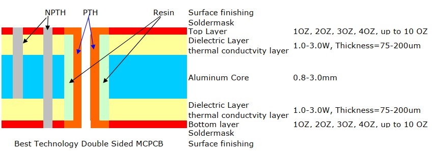
A double sided metal core PCB also has same two layers of copper conductor like Double layers MCPCB, but the metal core is in the middle of two conductor, so there’re conductors (trace) on both sides of metal core, and were connected to each other by Vias. So we named it “Double sided MCPCB”, and you can populated SMD on both top and bottom.
Different with Single layer MCPCB, double sided MCPCB also requires an additional pressing step to laminate the imaged thermal conductive laminate and metal core (also known as metal base) together. But sometimes, some raw Metal Clad material vendor will supply board material which already laminated.
Compared with normal FR4, this structure need more technology and experience on laminating of two layers together with metal core.
Structure of Double Sided MCPCB
Capability of Double Sided MCPCB
- Base material: Aluminum/Copper/Iron Alloy
- Thermal Conductivity (dielectric layer): 0.8, 1.5, 2.0, 3.0 W/m.K.
- Board Thickness: 0.5mm~3.0mm (0.02″~0.12″)
- Copper thickness: 0.5 OZ, 1.0 OZ, 2.0 OZ, 3.0 OZ, 4.0 OZ, 5.0 OZ
- Outline: Routing, punching, V-Cut
- Solder mask: White/Black/Blue/Green/Red Oil
- Legend/Silkscreen Color: Black/White
- Surface finishing: Immersion Gold, HASL, OSP
- Max Panel size: 600*500mm (23.62″*19.68″)
- Packing: Vacuum/Plastic bag
- Samples L/T: 10~15 Days
- MP L/T: 12~15 Days
FAQs about Double sided Metal Core PCB
1. What is a double-sided metal core PCB?
A double-sided MCPCB consists of two circuit layers (top and bottom) with a metal core—typically aluminum or copper—sandwiched in the middle. Unlike standard FR4 boards, the metal core acts as a high-efficiency heat sink. The layers are connected using insulated through-holes or thermal vias to ensure electrical signals pass through without shorting against the metal base.
2. How does a double-sided MCPCB differ from a single-sided one?
The primary difference lies in component density and routing complexity.
- Single-Sided: Components are on one side; the metal base is on the back. It is simpler and cheaper but limited in space.
- Double-Sided: Allows for components and traces on both sides of the metal core. This is necessary for complex designs where high power density requires cooling for components on both surfaces of the board.
3. What materials are used for the core in double-sided PCBs?
The three most common materials are:
- Aluminum (6061 or 5052): The most cost-effective and popular choice, offering good thermal conductivity and mechanical stability.
- Copper: Offers superior thermal conductivity (nearly double that of aluminum) but is significantly heavier and more expensive.
- Stainless Steel: Used primarily for its mechanical strength and corrosion resistance, though its thermal performance is lower than aluminum.
4. Why are double-sided MCPCBs used instead of standard FR4?
Standard FR4 is a poor thermal conductor. In high-power applications, heat builds up and can cause component failure. Double-sided MCPCBs are used because the metal core can dissipate heat at rates of 1.0 W/mK to 9.0 W/mK (or higher), whereas FR4 typically manages only 0.25 W/mK. This allows for smaller form factors without overheating.
5. What are the main applications for double-sided metal core PCBs?
These boards are a staple in industries where heat management is critical:
- Automotive: LED headlights, power converters, and motor control modules.
- Lighting: High-output street lights and industrial floodlights.
- Power Electronics: Solid-state relays, rectifiers, and high-capacity power supplies.
- Telecommunications: Signal amplifiers and high-frequency filtering equipment.
6. What are the manufacturing challenges of double-sided MCPCBs?
The most significant challenge is the drilling and insulation process. Because the core is conductive metal, every through-hole must be pre-drilled, filled with a specialized dielectric resin, and then re-drilled to prevent the copper pins from touching the metal core. This requires high precision and specialized lamination techniques to ensure the board does not delaminate under thermal stress.