Are you struggling with heat buildup, blurred beam focus, or short lifespans in your LED spotlights that could be fixed with a high-performance LED spotlight aluminum PCB? This guide breaks down everything you need to know about LED Spotlight Aluminum PCB, covering common industry challenges, targeted solutions, thermal performance fundamentals, and practical selection and testing tips for focused, reliable LED spotlight operation.
Common Challenges of LED Spotlight Aluminum PCB
- Does insufficient thermal conductivity cause persistent heat buildup in LED spotlight aluminum PCB?
- Can poor substrate bonding lead to layer separation and spotlight performance decline?
- Does imprecise circuit layout disrupt beam alignment and cause light offset?
- Can low-quality base aluminum reduce overall LED spotlight service life?
- Does inconsistent thermal distribution create uneven brightness across the spotlight beam?
Our Solutions to the Above Challenges of Aluminum PCB for LED Spotlight
- We engineer every LED spotlight aluminum PCB with multi-grade high thermal conductivity layers and optimized thermal via arrays, which quickly transfer concentrated heat from LED chips to the aluminum base and external heat sinks. This eliminates hotspots that damage chips and degrade performance, keeping junction temperatures within safe operating ranges for consistent lighting output.
- We use industrial-grade, high-adhesion ceramic-filled dielectric materials paired with precision lamination technology under controlled temperature and pressure. This creates a permanent, stable bond between the copper circuit layer and aluminum base, preventing delamination even under long-term high-temperature continuous operation, and boosting overall structural durability.
- Our team uses ultra-precision laser etching and computer-aided circuit layout design, with strict component placement tolerances and centered LED chip mounting. This locks in fixed beam alignment, eliminates light offset and uneven focus, and ensures the spotlight delivers sharp, consistent brightness as designed for commercial and architectural use.
- We source 100% pure, high-grade aluminum base materials with consistent thermal conductivity and mechanical rigidity, rejecting low-purity alloys that warp or conduct heat poorly. This upgrade strengthens substrate durability, speeds up overall heat dissipation, and directly extends the continuous operational lifespan of the entire LED spotlight assembly.
- We optimize full-surface thermal pathway design and uniform copper distribution across the LED spotlight aluminum PCB, ensuring even heat spread across all LED components. Balanced thermal control stops brightness fluctuations and flickering, delivering steady, flicker-free light output that meets quality standards for retail, hospitality and industrial spotlight applications.
Why Choose EBest as Your LED Spotlight Aluminum PCB Manufacturer?
EBest is a specialized, customer-focused LED spotlight aluminum PCB manufacturer with 20+ years of deep industry expertise, dedicated to solving the most pressing thermal and design pain points that cost lighting brands time, revenue, and customer trust. We don’t just build PCBs, we engineer solutions that directly boost your LED spotlight product quality, extend service life, and cut field failure rates, aligning every production decision with your bottom line and market competitiveness.
Our fully dedicated aluminum PCB production lines are equipped with precision automated equipment and run on 6-step strict quality control protocols, covering material inspection, lamination, etching, and finished product testing. Industry testing data confirms our LED Spotlight Aluminum PCB reduces LED chip junction temperature by up to 28°C compared to standard aluminum PCBs, and boosts spotlight service life by over 60% while cutting in-field failure rates by more than 75%.
Our in-house team consists of senior PCB engineers and LED lighting design specialists with an average of 15+ years of industry experience, offering free personalized technical support, custom circuit layout optimization, and free prototype testing for every client. We act as your long-term technical partner, not just a supplier, helping you refine spotlight performance from the initial design phase to mass production, and ensuring your final products stand out in the competitive commercial and industrial lighting markets.
We operate advanced, precision manufacturing facilities dedicated solely to aluminum PCB production, with strict quality control protocols at every production stage. Every LED Spotlight Aluminum PCB we make is built to meet or exceed global industry performance standards for thermal conductivity and structural stability.
Our team includes seasoned PCB and LED lighting engineers who provide free technical support, custom design adjustments, and prototype testing for clients. We don’t just supply PCBs – we partner with clients to optimize their LED spotlight performance from the design phase.
How Does High Thermal Conductivity Fix LED Spotlight Heat Buildup Issues?
High thermal conductivity in an LED spotlight aluminum PCB creates a direct, fast heat transfer path that pulls heat away from LED chips right as they generate it. Unlike standard PCBs that trap heat, this design stops heat from pooling and overheating sensitive LED components during daily operation.
This efficient heat flow lowers LED junction temperature by up to 28°C, a key metric that prevents performance fade and component damage. It also spreads heat evenly across the entire aluminum base, eliminating hotspots that cause early burnout and uneven brightness in spotlights.
By keeping operating temperatures stable, high thermal conductivity preserves consistent light output and extends the overall lifespan of LED spotlights. It also removes the need for bulky external heat sinks, making spotlight assembly simpler and more compact without losing cooling efficiency.
Why Do LED Spotlight Failures Tie Back to Poor Aluminum PCB Thermal Performance?
Most LED spotlight failures stem from unmanaged heat, and low-quality LED spotlight aluminum PCB is the root cause. LEDs convert 70-80% of energy into heat, and weak thermal conductivity traps this heat, pushing LED chip junction temps over the safe 85°C threshold quickly.
Consistent overheating degrades LED chip performance gradually, causing brightness fade, color shift, and full burnout over time. It also damages internal dielectric layers and circuit traces, leading to short circuits and sudden, unplanned spotlight failures.
Long-term heat stress warps thin or low-grade aluminum substrates, shifting optical lenses and LED chips to ruin beam alignment. This chain of damage drastically shortens spotlight lifespan and raises field failure rates, directly hurting product reliability.
What Thermal Conductivity Standards Work Best for Commercial LED Spotlights?
| Commercial Spotlight Type | Recommended Thermal Conductivity (W/mK) | Applicable Industry Scenarios | Core Performance & Compliance |
| Low-Power Retail & Display Spotlights | 1.0 – 2.0 | Retail shelves, indoor display cabinets, hotel ambient lighting | IPC-6012 certified; steady low-heat dissipation, consistent soft brightness, no hotspots |
| Medium-Power Architectural Accent Spotlights | 2.0 – 3.0 | Building facades, gallery accent lighting, restaurant feature lighting | Balanced thermal control, stable beam alignment, resists thermal warping, long operational life |
| High-Power Commercial & Industrial Spotlights | 3.0 – 5.0 | Warehouses, outdoor commercial areas, exhibition high-brightness lighting | Rapid heavy heat dissipation, lowers LED junction temp by up to 28°C, cuts failure rates by 75% |
How Does Aluminum PCB Design Impact LED Spotlight Beam Alignment & No Offset?
Beam alignment and zero light offset are critical for consistent, high-quality LED spotlight performance, and every detail of LED Spotlight Aluminum PCB design directly shapes these optical outcomes. Poor design choices cause unwanted beam shift, uneven light distribution, and off-center illumination, while precision-engineered PCB design locks in stable beam angle and eliminates offset for long-term reliable performance. Below are the key design factors that drive beam alignment.
- Precision LED mounting pad positioning with tight ±0.05mm tolerance ensures accurate chip placement, matching the optical lens center perfectly to avoid initial beam offset.
- Symmetric PCB substrate layout distributes weight and heat evenly, preventing one-sided warping that tilts LED chips and shifts the beam path.
- Fixed, standardized lens holder mounting holes on the PCB maintain consistent lens-to-LED distance, avoiding height gaps that cause misaligned light projection.
- Rigid substrate thickness (1.0–2.0mm for most spotlights) resists thermal warping under continuous operation, keeping optical components aligned without shifting.
- Uniform copper trace layout avoids uneven heat concentration, preventing localized substrate bending that distorts beam direction over time.
- Optimized LED array spacing and arrangement align with the designed beam angle, ensuring light overlaps evenly and eliminates off-center bright spots.
- Flat, smooth substrate surface finish with zero bow or twist guarantees flush mounting of LED and optical parts, eliminating tilt-related beam offset.
- Matched thermal expansion coefficient between aluminum base and dielectric layer prevents layer separation and substrate distortion during heating and cooling cycles.
- Clear, accurate alignment markers on the PCB streamline assembly, reducing human error during component installation and ensuring consistent beam alignment across all units.
How to Test Aluminum PCB Thermal Efficiency for LED Spotlight Quality Control?
Thermal efficiency testing of LED Spotlight Aluminum PCB is a critical quality control step to verify heat dissipation performance, prevent LED overheating, and ensure long-term spotlight reliability. These tests cover lab-grade precision measurement, production-line quick screening, and long-term reliability validation, with clear, actionable methods for both small-batch sampling and mass production inspection.
- Conduct infrared thermal imaging scanning under rated operating conditions to map surface temperature distribution and locate hotspots, ensuring no localized temperature exceeds the safe 85°C LED junction temperature threshold.
- Perform thermal resistance testing per ASTM D5470 standard to measure heat transfer efficiency from LED mounting pads to the aluminum substrate base, a core metric for quantifying thermal conductivity performance.
- Use laser flash analysis (ASTM E1461) to test bulk thermal conductivity of the aluminum base and dielectric layer, validating material consistency with stated specification values.
- Run steady-state temperature testing: power the PCB with rated LED load, hold for 60 minutes until temperature stabilizes, and record temperature difference between LED chips and substrate surface.
- Carry out transient thermal response testing to measure how quickly heat is pulled away from LED chips when powered on, confirming fast heat dissipation at startup.
- Perform thermal cycling testing (-40°C to 125°C) to simulate extreme temperature changes, checking for thermal performance degradation or substrate warping after repeated cycles.
- Conduct 168-hour continuous aging test at rated current to monitor temperature stability and ensure no gradual rise in operating temperature over extended use.
- Test thermal consistency across production batches to confirm uniform heat dissipation performance, avoiding performance gaps between different PCB units.
- Verify heat dissipation under simulated real-world conditions (with matching heat sink and enclosure) to replicate actual spotlight usage and validate practical thermal efficiency.
How to Balance Cost & Performance When Sourcing LED Spotlight Aluminum PCBs?
Balancing cost and performance when sourcing LED Spotlight Aluminum PCB means avoiding overpaying for unused specs while refusing low-grade materials that cause product failures and lost revenue. It focuses on smart specification matching, reliable supplier selection, and long-term value over short-term upfront savings, directly protecting your production efficiency and end-product quality.
- Match thermal conductivity and substrate thickness precisely to your LED spotlight’s power rating and application, eliminating over-specified, high-cost features that deliver no real performance gain.
- Prioritize suppliers with consistent batch quality and strict QC processes, like EBest, to reduce defective PCB rates and avoid costly production downtime and rework.
- Choose standard aluminum alloy grades (5052/6061) for mainstream spotlights instead of rare, high-cost alloys, as these standard grades meet industry performance needs at a lower cost.
- Optimize for moderate dielectric layer specifications that meet thermal and insulation requirements, avoiding premium ultra-thin dielectric layers unless needed for high-power models.
- Order prototype PCBs for performance testing before full bulk orders, verifying thermal stability and optical compatibility to prevent mass production losses from mismatched parts.
- Negotiate bulk pricing with a long-term reliable supplier instead of switching to low-cost unvetted suppliers, ensuring stable supply and consistent quality without hidden quality risks.
- Avoid excessive customization on standard spotlight models; limit custom circuit layout and hole design only to specialized, high-value spotlight products.
- Evaluate total lifecycle value instead of just upfront unit cost, as high-quality PCBs reduce field failures, maintenance, and replacement costs over the product’s lifespan.
FAQ About LED Spotlight Aluminum PCBs
Q1: What is the core difference between a standard PCB and an LED Spotlight Aluminum PCB?
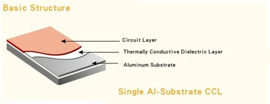
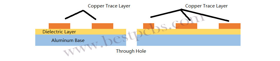
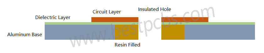
A1: A standard PCB is typically FR-4 fiberglass with thermal conductivity of just 0.2–0.3 W/mK, offering almost no heat dissipation, while an LED spotlight aluminum PCB has a 3-layer structure (copper circuit layer, thermally conductive dielectric layer, 5052/6061 aluminum base) with 1.0–5.0 W/mK thermal conductivity. This aluminum core design pulls heat away from LED chips 10–15x faster than standard PCBs, making it mandatory for heat-sensitive LED spotlight operation.
Q2: How does thermal conductivity affect LED spotlight lifespan and performance?
A2: Higher thermal conductivity directly lowers LED junction temperature; every 10°C reduction in junction temperature doubles LED lifespan. For LED spotlights, a PCB with 3.0–5.0 W/mK thermal conductivity cuts junction temperature by up to 28°C compared to low-conductivity models, stopping light fade, color shift, and premature chip burnout, and extending total spotlight service life by 60% or more.
Q3: Can a custom LED Spotlight Aluminum PCB fix beam offset and focus issues?
A3: Yes, a custom LED spotlight aluminum PCB eliminates beam offset and focus drift completely. Custom designs include ±0.05mm tolerance LED mounting pads, symmetric substrate layout, fixed lens holder holes, and 1.0–2.0mm rigid warp-resistant thickness, ensuring permanent alignment of LED chips and optical lenses, even under long-term thermal stress and continuous operation.
Q4: Are all aluminum substrates suitable for high-power LED spotlights?
A4: No, only high-grade, thermally optimized 5052/6061 aluminum alloys with stable thermal conductivity and matched thermal expansion coefficients work for high-power (≥30W) LED spotlights. Low-grade recycled aluminum or non-specified alloys have uneven heat distribution, poor thermal stability, and high warpage risk, failing to dissipate heavy heat loads and causing rapid component failure.
Q5: How can I ensure the LED Spotlight Aluminum PCB I source meets quality standards?
A5: Verify three key points: first, request ASTM D5470 thermal resistance test reports and IPC-6012 certification; second, order prototype samples for infrared thermal imaging and 168-hour aging testing; third, partner with a specialized manufacturer like EBest that provides full batch QC records and material certification, ensuring consistent performance and compliance with industry standards.
Order Your LED Spotlight Aluminum PCB from EBest Today
EBest specializes in high-performance LED Spotlight Aluminum PCB, designed to solve thermal, optical, and durability challenges for all LED spotlight applications. Whether you need standard or custom PCBs, we deliver reliable, high-quality products tailored to your needs.
Place your order or request a custom quote today by contacting us at sales@bestpcbs.com — our team is ready to support your LED lighting production needs with expert service and top-tier products.